A strain sensor is used to measure very small deformation in a machine part, structure, frame, shaft, or mechanical component.
In industrial automation, strain sensors are often used when we want to monitor force indirectly.
Instead of placing a force sensor directly in the force path, a strain sensor is mounted onto the surface of an existing machine structure. When the structure bends, stretches, or compresses, the strain sensor detects that deformation.
This makes strain sensors useful for:
Press machines
Injection molding machines
Clamping systems
Roller force monitoring
Machine frames
Lifting systems
Forming machines
Mechanical overload detection
Large force measurement
Structural monitoring
Industrial process control
The basic idea is simple:
Force causes deformation.
Deformation creates strain.
The strain sensor measures that strain.
From the strain, the force can be estimated.
What Is Strain?
Strain is the relative change in length of a material when it is loaded.
When a component is pulled, it becomes slightly longer.
When a component is compressed, it becomes slightly shorter.
This change can be caused by:
Tension
Compression
Bending
Torque
Mechanical force
Temperature expansion
Machine loading
In strain measurement, we are mainly interested in mechanical strain caused by force.
For example, if a steel beam is loaded, it may stretch only a tiny amount. This deformation may be too small to see with the eye, but a strain sensor can detect it.
Positive and Negative Strain
Strain can be positive or negative.
Positive Strain
Positive strain means the material is stretched.
Example:
A rod is pulled in tension and becomes slightly longer.
Negative Strain
Negative strain means the material is compressed.
Example:
A column is pressed and becomes slightly shorter.
So:
Stretching = positive strain
Compression = negative strain
How Is Strain Calculated?
Strain is calculated as the change in length divided by the original length.
The formula is:
ε = ΔL / L₀
Where:
ε = strain
ΔL = change in length
L₀ = original length
Strain has no dimension because it is a ratio of length to length.
For example, if a 1 meter part becomes longer by 0.001 meter:
ε = 0.001 / 1 = 0.001 m/m
But in real machine parts, strain is usually much smaller than this.
That is why strain is often shown in:
µm/m
or
microstrain / µε
What Does µm/m Mean?
The unit µm/m means micrometers per meter.
1 µm = 0.000001 m
So if a component has a strain of 500 µm/m, it means that every 1 meter of material changes length by 500 micrometers.
In many industrial applications, strain values are very small, so using µm/m makes the numbers easier to read.
Examples:
100 µm/m = small strain
500 µm/m = common industrial strain range
1000 µm/m = larger strain
2000 µm/m = high strain for many sensor applications
Why Is Strain Measured?
Strain is measured because it tells us how much a structure is being mechanically loaded.
This can help with:
Force monitoring
Machine protection
Overload detection
Process control
Quality control
Wear monitoring
Structural health monitoring
Preventive maintenance
In many machines, it is not easy or practical to install a force sensor directly into the force path.
A strain sensor gives another option.
Instead of modifying the machine heavily, the sensor can often be mounted onto the surface of a machine component.
When the component deforms under load, the sensor measures the strain.
From that strain, the force can be calculated or calibrated.
Direct Force Measurement vs Indirect Force Measurement
There are two common ways to measure force:
Direct force measurement
Indirect force measurement
Direct Force Measurement
In direct force measurement, a force sensor is installed directly in the force path.
The force passes through the sensor.
Examples:
Load cells
Compression force sensors
Tension force sensors
Force washers
Force transducers
This method is usually very accurate because the sensor is directly loaded by the force.
But it may require changes to the mechanical design.
Indirect Force Measurement
In indirect force measurement, the force is not applied directly through the sensor.
Instead, a strain sensor is mounted onto a machine structure.
The machine structure deforms under load.
The strain sensor measures that deformation.
The force is then calculated or estimated from the strain.
This is useful when:
The force is very large
The machine structure is very stiff
There is no space for a force sensor
Changing the mechanical design is difficult
A lower-cost monitoring method is needed
The sensor must be added to an existing machine
When Should You Use a Strain Sensor?
A strain sensor is a good choice when you want to monitor large forces indirectly.
It is useful when:
The machine frame already carries the force
The force path is difficult to access
You do not want to redesign the machine
The force is too large for a simple small force sensor
You want to monitor deformation of a structure
You need overload detection
You need process force feedback
For example, on a press machine, the main frame deforms slightly when force is applied.
A strain sensor can be mounted on the frame and used to monitor the pressing force.
When Should You Use a Force Sensor Instead?
A force sensor is usually better when you need direct and accurate force measurement.
Use a force sensor when:
The force can pass directly through the sensor
High measurement accuracy is required
The mechanical design allows sensor installation
Calibration must be simpler
The force path is clear
You are designing a new machine and can include the sensor from the beginning
In simple terms:
Use a force sensor when you can measure the force directly.
Use a strain sensor when you need to measure force through machine deformation.
How Does Strain Lead to Force?
When a force is applied to a component, the component experiences stress and strain.
In the elastic range of the material, stress and strain are proportional.
This relationship is described by Hooke’s Law.
The basic relationship is:
σ = E × ε
Where:
σ = stress
E = elastic modulus / Young’s modulus
ε = strain
Stress can also be calculated from force and area:
σ = F / A
Where:
F = force
A = cross-sectional area
If we combine these formulas:
F / A = E × ε
So:
F = A × E × ε
This means that if we know the material, the cross-sectional area, and the measured strain, we can estimate the force.
Important Note About the Formula
This simple formula works best for a simple axial load in the linear elastic range.
Real machines can be more complex because of:
Bending
Torsion
Uneven load distribution
Complex geometry
Mounting position
Temperature effects
Material differences
Mechanical play
In real industrial applications, strain sensors are often calibrated on the machine.
This means a known force is applied, the sensor signal is recorded, and the system is scaled based on real measurement data.
Elastic Modulus Explained
The elastic modulus, also called Young’s modulus or E-module, describes how stiff a material is.
A material with a high elastic modulus is stiff.
A material with a low elastic modulus is flexible.
Typical examples:
Steel: about 210,000 N/mm²
Aluminum: about 70,000 N/mm²
Hard rubber: much lower, around a few N/mm² depending on type
Steel is much stiffer than aluminum.
That means that under the same force and geometry, aluminum will usually deform more than steel.
Example Calculation: From Strain to Force
Let’s use a simple example.
Measured strain:
240 µm/m
Steel bar size:
20 mm × 20 mm
Cross-sectional area:
A = 20 × 20 = 400 mm²
Elastic modulus of steel:
E = 210,000 N/mm²
Convert strain:
240 µm/m = 240 × 10⁻⁶ m/m
Formula:
F = A × E × ε
Calculation:
F = 400 × 210,000 × 240 × 10⁻⁶
F = 20,160 N
So the estimated force is:
20,160 N
That is about 20.16 kN.
Again, this is a simplified example. Real machines should be calibrated and checked based on actual mechanical conditions.
How Does a Strain Sensor Work?
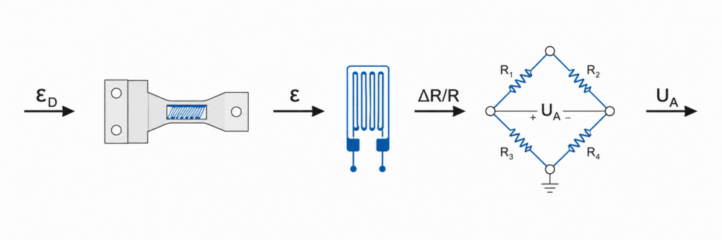
A strain sensor works by converting mechanical deformation into an electrical signal.
The basic process is:
A force loads the machine structure.
The structure deforms slightly.
The strain sensor follows this deformation.
Inside the sensor, strain gauges deform.
The strain gauges change electrical resistance.
A bridge circuit converts this resistance change into a voltage signal.
The amplifier or controller converts the signal into a usable measurement value.
The key part inside many strain sensors is the strain gauge.
What Is a Strain Gauge?
A strain gauge is a small electrical measuring element that changes resistance when it is stretched or compressed.
A typical strain gauge contains:
A thin backing film
A very fine metal measuring grid
A protective cover layer
The metal measuring grid is usually arranged in a thin zigzag or meander shape.
When the material below the strain gauge stretches, the grid stretches too.
When the grid stretches, its electrical resistance changes.
This resistance change is very small, but it can be measured accurately using a bridge circuit.
How a Strain Gauge Converts Movement Into Electricity
A strain gauge acts as a mechanical-electrical converter.
When strain increases, the resistance changes.
The relationship between strain and resistance change is described by the gauge factor, also called the k-factor.
The simplified idea is:
More strain = larger resistance change
Less strain = smaller resistance change
Because the resistance change is very small, the sensor electronics must be sensitive and stable.
That is why strain gauges are usually connected in a Wheatstone bridge.
What Is a Wheatstone Bridge?
A Wheatstone bridge is an electrical circuit used to measure very small resistance changes.
It is commonly used in strain gauge sensors.
A full Wheatstone bridge uses four resistive elements connected in a special arrangement.
In strain sensors, these resistive elements are often strain gauges.
The bridge is supplied with an excitation voltage.
When there is no strain, the bridge is balanced.
When strain changes the resistance of the gauges, the bridge becomes unbalanced.
This imbalance creates a small output voltage.
That voltage is proportional to the strain.
Why Is the Wheatstone Bridge Used?
The Wheatstone bridge is used because strain gauge resistance changes are tiny.
A normal resistance measurement would not be practical enough for precise industrial measurement.
The bridge circuit helps detect very small changes accurately.
It also improves:
Sensitivity
Stability
Noise performance
Temperature compensation
Signal quality
Many strain sensors use a full-bridge circuit because it gives a stronger and more stable measurement signal.
Typical Strain Sensor Output Signal
Many strain gauge-based sensors produce a very small output signal.
A common signal range is around:
0.4 to 3.0 mV/V
This means the output depends on the excitation voltage.
For example, if a sensor has a sensitivity of 2 mV/V and is supplied with 10V, the full-scale output is:
2 mV/V × 10V = 20 mV
That is a very small signal.
Because of this, many industrial strain sensors include built-in amplifier electronics.
With amplification, the output may be converted to more usable signals such as:
0–10V
4–20 mA
IO-Link
Digital communication
Fieldbus signal
PLC analog input signal
Passive and Active Strain Sensors
Strain sensors can be passive or active.
Passive Strain Sensors
A passive strain sensor usually provides the raw strain gauge bridge signal.
It needs external electronics for:
Bridge excitation
Signal amplification
Filtering
Scaling
Temperature compensation
Passive sensors are useful when the control system already has a suitable strain gauge amplifier.
Active Strain Sensors
An active strain sensor includes integrated electronics.
It may provide an industrial output such as:
4–20 mA
0–10V
Digital output
IO-Link
Fieldbus communication
Active sensors are easier to connect to PLC systems because the signal is already amplified and conditioned.
Basic Types of Strain Sensors
There are different types of strain sensors depending on installation, size, environment, and signal output.
1. Screw-On Strain Sensors
These sensors are mounted directly onto a machine surface using screws.
They are useful because they create repeatable mounting conditions.
Compared with glued strain gauges, screw-on sensors are often easier to install in industrial production.
They are used for:
Machine frames
Presses
Clamping systems
Roller force monitoring
Industrial machines
Retrofit applications
2. Miniature Strain Sensors
Miniature strain sensors are used where installation space is limited.
They are useful in compact machines or tight mechanical areas where a larger sensor cannot fit.
Applications include:
Small machine modules
Compact mechanisms
Limited mounting space
Small industrial fixtures
3. Standard Industrial Strain Sensors
Standard strain sensors are used for general machine monitoring.
They are often designed for indoor industrial environments and typical measurement ranges.
They may include integrated amplifier electronics and provide easy connection to control systems.
Applications include:
Factory machines
Assembly systems
Press monitoring
Force monitoring
Automation equipment
4. High-Performance Strain Sensors
Some strain sensors are designed for wider measuring ranges or lower stiffness influence.
Low stiffness influence is important because the sensor should not significantly affect the mechanical behavior of the machine.
These sensors are useful when:
Small strains must be measured
Large strain ranges are needed
High repeatability is required
Machine structure influence must be minimal
5. Robust Outdoor Strain Sensors
Some strain sensors are designed for harsh environments.
They may have:
High IP protection
Corrosion-resistant housing
Sealed construction
Outdoor rating
High vibration resistance
Long-term environmental protection
These sensors are useful for:
Outdoor machinery
Lifting systems
Heavy equipment
Harsh industrial areas
Mobile machines
Wet or dirty environments
6. Drill-Hole Strain Sensors
Some strain sensors measure strain through a drilled hole in the component.
This can be useful when surface mounting is not ideal or when the mechanical design requires another measurement method.
These sensors are more application-specific and should be installed according to the manufacturer’s instructions.
Common Strain Gauge Designs
Strain gauges themselves can have different layouts.
Common types include:
Linear strain gauges
T-rosette strain gauges
Rosette strain gauges
Shear strain gauges
Linear Strain Gauge
A linear strain gauge measures strain mainly in one direction.
It is used when the strain direction is known.
Rosette Strain Gauge
A rosette strain gauge measures strain in multiple directions.
It is useful when the direction of strain is unknown or complex.
Shear Strain Gauge
A shear strain gauge is used for measuring shear strain.
It is common in torque and load measurement applications.
Are Strain Sensors Fatigue Resistant?
Many industrial strain sensors are designed for repeated loading.
This is important because machines often apply force thousands or millions of times.
For example:
Press cycles
Clamping cycles
Forming cycles
Lifting cycles
Machine vibration
Alternating tension and compression
A good strain sensor should withstand repeated positive and negative strain cycles within its rated range.
Many industrial strain sensors are designed for millions of cycles, but the exact fatigue life depends on:
Sensor design
Mounting quality
Strain range
Overload events
Temperature
Vibration
Mechanical installation
Environmental conditions
Always check the sensor datasheet for fatigue rating and overload limits.
Important Installation Factors
Strain sensor performance depends heavily on installation.
Even a good sensor can give poor readings if it is mounted incorrectly.
Check these points:
Mounting surface must be clean and flat
Sensor must be installed in the correct direction
Screws must be tightened correctly
Cable must be protected from pulling
Sensor should not be mounted on weak or loose material
Temperature influence should be considered
The structure must deform consistently
Mounting position must match the measurement goal
For screw-on sensors, the tightening torque of the mounting screws is important.
If the sensor is mounted loosely, it may not follow the deformation correctly.
If it is mounted incorrectly, the signal may be unstable or inaccurate.
Strain Sensor Output to PLC
In automation, strain sensors are often connected to a PLC or controller.
Depending on the sensor type, the signal may be:
Raw mV/V bridge signal
0–10V analog signal
4–20 mA analog signal
Digital communication
IO-Link
Fieldbus
A raw mV/V signal cannot usually be connected directly to a standard PLC analog input.
It needs a strain gauge amplifier.
For PLC systems, 4–20 mA or 0–10V sensors are easier to use.
Simple PLC Example
Imagine a press machine where you want to monitor pressing force.
A strain sensor is mounted on the machine frame.
When the press applies force, the frame deforms slightly.
The strain sensor detects the deformation.
The sensor amplifier sends a 4–20 mA signal to the PLC.
The PLC scales the signal into force, for example:
4 mA = 0 kN
20 mA = 100 kN
The HMI then displays the pressing force.
The PLC can also use this value for:
High force alarm
Low force alarm
Process monitoring
Part quality check
Machine protection
Overload shutdown
This is a common way strain sensors are used in automation.
Advantages of Strain Sensors
Strain sensors have several advantages.
1. Indirect Measurement of Large Forces
Large forces can be monitored without placing a huge force sensor directly in the force path.
2. Good for Existing Machines
They can often be added to existing machine structures.
3. Compact Size
Strain sensors can be small compared with direct force sensors.
4. Useful for Process Monitoring
They can show how much mechanical load is applied during a process.
5. Cost-Effective for Large Forces
In some applications, indirect force measurement can be cheaper than a large direct force sensor.
Limitations of Strain Sensors
Strain sensors are useful, but they are not perfect.
1. Calibration Is Important
The relationship between strain and force depends on the machine structure.
For accurate force measurement, calibration is usually needed.
2. Installation Affects Accuracy
Bad mounting can cause bad readings.
3. Temperature Can Influence Measurement
Temperature changes can create thermal strain or signal drift.
4. Mechanical Structure Matters
If the structure is too stiff, the strain may be too small.
If the structure is too flexible, it may deform too much.
5. They Measure Local Strain
A strain sensor measures strain at its mounting location.
If the mounting position is not representative of the force, the measurement may not be useful.
How to Choose a Strain Sensor
Before choosing a strain sensor, check:
Expected strain range
Positive and negative strain direction
Machine material
Mounting surface
Available space
Indoor or outdoor environment
Temperature range
IP protection
Cable connection
Passive or amplified output
PLC input compatibility
Required accuracy
Cycle life
Overload protection
Calibration method
Mounting screw requirements
For PLC and automation work, also check:
Does the sensor output 4–20 mA or 0–10V?
Do I need a strain gauge amplifier?
Can the PLC scale the signal properly?
Is the sensor range suitable for the machine load?
Is the sensor protected from vibration, oil, water, and dirt?
Final Thoughts
A strain sensor measures the tiny deformation of a mechanical component.
This deformation is called strain.
Strain is calculated as:
ε = ΔL / L₀
When a force is applied to a structure, the structure deforms. In the elastic range, the strain is related to stress through Hooke’s Law:
σ = E × ε
And for simple axial loading, force can be estimated as:
F = A × E × ε
Inside many strain sensors, strain gauges convert mechanical deformation into a small electrical resistance change.
A Wheatstone bridge circuit then converts this resistance change into a measurable voltage signal.
In industrial automation, strain sensors are useful because they allow indirect force measurement on real machine structures.
The most important idea is:
A strain sensor does not measure force directly.
It measures deformation, and that deformation can be used to calculate or estimate force.