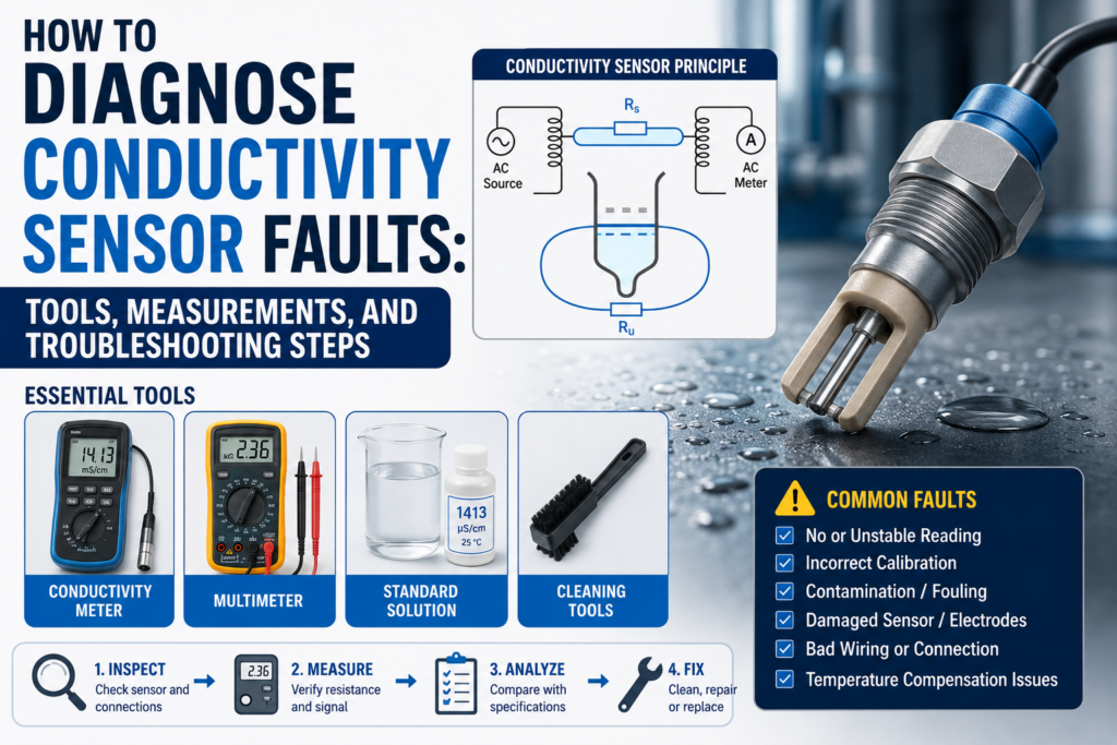
A conductivity sensor is used to measure how well a liquid conducts electricity.
In industrial automation, conductivity sensors are used for:
Water treatment
CIP cleaning
Media separation
Chemical concentration monitoring
Rinse water control
Food and beverage processes
Chemical dosing
Process monitoring
PLC control systems
When a conductivity sensor gives a wrong value, the problem is not always the sensor itself.
The fault can come from:
Wrong sensor type
Wrong conductivity range
Dirty electrodes
Coating or deposits
Air bubbles
Partially filled pipe
Wrong temperature compensation
Bad calibration
Wrong 4–20 mA scaling
Wrong PLC scaling
Damaged cable
Poor grounding
Electrical noise
Wrong installation position
Low liquid conductivity
Wrong process material compatibility
Failed temperature element
Transmitter fault
The best way to diagnose a conductivity sensor is to test the system step by step.
Important Safety Note
Conductivity sensors are often installed in process lines with water, chemicals, acids, caustic solutions, hot liquids, or cleaning chemicals.
Before troubleshooting:
Follow lockout/tagout procedures.
Check if the pipe is pressurized.
Check if the liquid is hot, corrosive, toxic, or hazardous.
Wear correct PPE.
Do not remove the sensor from the process unless the line is isolated, drained, and safe.
Do not use an insulation tester on transmitter electronics or PLC inputs.
Always check the sensor manual before applying test voltage.
Conductivity measurement is simple in theory, but the process environment can be dangerous.
How a Conductivity Sensor Should Work
A conductivity sensor measures how easily current can pass through a liquid.
The liquid conducts electricity because it contains ions.
More ions usually mean higher conductivity.
Fewer ions usually mean lower conductivity.
Common units are:
µS/cm — microsiemens per centimeter
mS/cm — millisiemens per centimeter
The relationship is:
1000 µS/cm = 1 mS/cm
A conductivity transmitter usually converts the sensor signal into:
Local display value
4–20 mA output
0–10V output
Relay output
Switching output
IO-Link value
Modbus value
HART value
Fieldbus value
The PLC then uses this value for alarms, dosing, media detection, cleaning control, or process decisions.
Conductive vs Inductive Conductivity Sensors
Before diagnosing a fault, identify which type of conductivity sensor you have.
There are two main types:
Conductive conductivity sensor
Inductive conductivity sensor
Conductive Conductivity Sensor
A conductive sensor uses electrodes that touch the liquid directly.
The transmitter applies a signal between the electrodes and measures how much current flows through the liquid.
Conductive sensors are usually good for:
Low conductivity water
Clean water
Pure water
General water treatment
Low and medium conductivity ranges
Common problems with conductive sensors include:
Dirty electrodes
Coating
Scaling
Corrosion
Polarization
Air bubbles
Broken electrode cable
Wrong cell constant
Wrong calibration
Inductive Conductivity Sensor
An inductive sensor uses coils and electromagnetic induction.
It normally does not have exposed metal electrodes in direct contact with the liquid.
Inductive sensors are usually good for:
High conductivity liquids
Acids
Caustic solutions
CIP cleaning chemicals
Food and beverage processes
Dirty liquids
Media separation
Applications with deposits
Common problems with inductive sensors include:
Wrong range for low conductivity
Air in the measuring channel
Coating or blockage in the sensor opening
Wrong temperature compensation
Wrong calibration
Cable or transmitter fault
Incorrect installation position
A very important point:
Inductive conductivity sensors are usually not the best choice for very low conductivity liquids.
For low conductivity measurement, a conductive sensor is usually better.
Common Conductivity Sensor Fault Symptoms
Common symptoms include:
No display
No conductivity reading
Reading stuck at zero
Reading stuck at maximum
Reading too high
Reading too low
Reading unstable
Reading changes with temperature
PLC value does not match sensor display
4–20 mA output stuck at 4 mA
4–20 mA output stuck at 20 mA
Output below 4 mA or above 20 mA
Wrong media separation
Wrong CIP step detection
Temperature reading wrong
Calibration fails
Sensor responds slowly
Conductivity value drifts over time
Alarm relay not switching
Communication fault
Each symptom has different possible causes.
Tools Needed for Conductivity Sensor Troubleshooting
1. Digital Multimeter
Use a multimeter to check:
24V DC power supply
AC supply if used
4–20 mA loop current
0–10V output
Cable continuity
Relay contacts
Temperature sensor resistance
Grounding problems
Loose terminals
This is the first tool to use.
2. Loop Calibrator / Process Meter
A loop calibrator is very useful for 4–20 mA systems.
Use it to:
Measure the transmitter output current
Simulate 4–20 mA into the PLC input
Check PLC scaling
Check HMI scaling
Prove whether the fault is in the sensor or PLC
If the sensor display is correct but the PLC value is wrong, use a loop calibrator.
3. Conductivity Calibration Solutions
Calibration solutions are very important.
Common values include:
84 µS/cm
1413 µS/cm
12.88 mS/cm
111.8 mS/cm
The exact solution depends on the sensor range.
Use fresh calibration solution and avoid contamination.
Do not pour used solution back into the bottle.
4. Handheld Conductivity Meter
A handheld reference meter is useful for comparing the process liquid.
Use it to check:
Is the liquid actually conductive?
Is the inline sensor close to a reference reading?
Is the process changing?
Is the installed sensor wrong or is the liquid actually different?
The handheld meter should be calibrated before use.
5. Thermometer / Temperature Probe
Conductivity depends strongly on temperature.
Use a thermometer to compare:
Actual liquid temperature
Sensor temperature value
Transmitter temperature reading
PLC temperature value
A bad temperature reading can create a wrong compensated conductivity value.
6. Insulation Tester
Use carefully.
An insulation tester can help find:
Damaged cable insulation
Moisture in junction boxes
Shorts to ground
Water inside connector
But do not insulation-test connected transmitter electronics or PLC inputs.
Disconnect the sensor cable first and follow the manufacturer manual.
7. Oscilloscope
Useful for difficult noise problems.
Use it to check:
Output signal noise
Power supply ripple
Electrical interference
Switching spikes
VFD-related noise
Unstable analog output
Not always needed, but useful for hard faults.
8. PLC Software / HMI Diagnostics
Use PLC software to check:
Raw analog input value
Scaled conductivity value
Engineering units
Analog input configuration
Alarm logic
4–20 mA range
Communication status
Data registers
HMI display scaling
Many “bad sensor” problems are actually PLC scaling problems.
9. Manufacturer Configuration Tool
If the transmitter supports digital configuration, use the software or display menu to check:
Measurement range
Cell constant
Sensor type
Temperature compensation
Temperature coefficient
Output range
Alarm current
Relay settings
Damping
Calibration history
Diagnostic messages
Communication address
This can save a lot of time.
Step 1: Check the Local Display First
If the conductivity transmitter has a display, start there.
Check:
Does it power on?
Does it show conductivity?
Does it show temperature?
Does it show an alarm?
Does it show sensor error?
Does it show range overflow?
Does it show calibration error?
Does the local value match the PLC value?
This separates the problem.
If the Display Is Correct but PLC Is Wrong
The problem is probably in:
4–20 mA wiring
PLC analog input
PLC scaling
HMI scaling
Communication mapping
Wrong units
Wrong output range
If the Display Is Wrong Too
The problem may be in:
Sensor
Process liquid
Calibration
Temperature compensation
Installation
Dirty electrodes
Coating
Air bubbles
Wrong range
Power supply
Transmitter settings
Step 2: Check Power Supply Voltage
Many conductivity transmitters use 24V DC.
Measure the voltage at the transmitter terminals.
Good 24V DC Reading
For many industrial instruments:
20.4V DC to 28.8V DC is usually acceptable.
That is 24V ±20%.
Always check the device manual.
Bad Readings
0V
Wrong polarity
Below 20V
Unstable voltage
Voltage drops when output changes
High AC ripple
Loose 0V/common terminal
Power supply overloaded
Measure voltage with the transmitter connected.
A power supply may look good without load but fail under load.
Step 3: Check the 4–20 mA Output
Many conductivity transmitters send the value to the PLC using a 4–20 mA signal.
For a normal range:
| Process Value | Expected Current |
|---|---|
| 0% | 4 mA |
| 25% | 8 mA |
| 50% | 12 mA |
| 75% | 16 mA |
| 100% | 20 mA |
Example:
If the transmitter range is:
0–100 mS/cm = 4–20 mA
Then:
4 mA = 0 mS/cm
12 mA = 50 mS/cm
20 mA = 100 mS/cm
If the transmitter range is:
0–10 mS/cm = 4–20 mA
Then:
4 mA = 0 mS/cm
12 mA = 5 mS/cm
20 mA = 10 mS/cm
So before judging the mA value, always check the configured range.
Good 4–20 mA Readings
Around 4 mA at 0% of range
Around 12 mA at 50% of range
Around 20 mA at 100% of range
Current changes smoothly when conductivity changes
Measured current matches local display and configured range
Bad 4–20 mA Readings
| Reading | Possible Problem |
|---|---|
| 0 mA | Broken loop, no power, wrong wiring |
| Below 3.6 mA | Fault alarm on many devices |
| 4 mA all the time | Zero value, output stuck, wrong range, sensor not measuring |
| 20 mA all the time | Overrange, wrong range, output saturated |
| Above 21 mA | Fault alarm or overrange on many devices |
| Random jumping | Noise, loose wire, process instability, air bubbles |
| Correct display but wrong mA | Output configuration fault |
| Correct mA but wrong PLC value | PLC scaling fault |
Alarm current values depend on transmitter settings.
Check the manual or configuration.
Step 4: Simulate the PLC Input
If the local display and measured 4–20 mA output are correct, but the PLC value is wrong, simulate the PLC input.
Use a loop calibrator.
| Simulated Current | PLC Should Show |
|---|---|
| 4 mA | 0% of range |
| 8 mA | 25% of range |
| 12 mA | 50% of range |
| 16 mA | 75% of range |
| 20 mA | 100% of range |
If the PLC does not show the correct value, the problem is not the sensor.
The problem is likely:
Wrong PLC scaling
Wrong analog input type
Wrong HMI scaling
Wrong engineering range
Wrong units
Wrong channel
Broken analog input
Wrong common wiring
Step 5: Check PLC Scaling and Units
Conductivity scaling mistakes are common.
Check if the PLC and HMI use the same units as the transmitter.
Common unit mistakes:
µS/cm vs mS/cm
0–100 mS/cm vs 0–1000 µS/cm
Temperature-compensated value vs raw value
Conductivity vs concentration
Wrong decimal point
Wrong maximum range
Remember:
1000 µS/cm = 1 mS/cm
So if the transmitter shows 1.413 mS/cm, the PLC should not show 1.413 µS/cm.
That would be wrong by a factor of 1000.
Step 6: Check the Actual Process Liquid
Before blaming the sensor, check the liquid.
Ask:
Is the correct liquid in the pipe?
Is the pipe full?
Is there air in the line?
Is the chemical concentration correct?
Is the liquid mixed properly?
Is the temperature stable?
Is the sensor installed in the correct process step?
Is the process actually changing?
Use a handheld conductivity meter to test a sample.
Good
Inline sensor and handheld reference are reasonably close
Sample is stable
Temperature is known
Correct conductivity range is used
Bad
Handheld meter shows completely different value
Sample changes quickly after collection
Liquid is not mixed
Air bubbles present
Wrong chemical in line
Conductivity below sensor range
Sensor installed in dead leg or stagnant area
A sensor cannot give a good reading if the process condition is not suitable.
Step 7: Check Calibration With Standard Solutions
Calibration solution is one of the best ways to test a conductivity sensor.
Use a solution that matches the sensor range.
Common calibration points:
84 µS/cm — low range
1413 µS/cm — general water range
12.88 mS/cm — medium range
111.8 mS/cm — high range
Good Calibration Result
Sensor reading is close to the calibration solution value
Temperature compensation is correct
Reading stabilizes quickly
Calibration is accepted by transmitter
Repeat test gives similar result
A reasonable field expectation is often within a few percent, depending on the sensor, solution, and accuracy requirement.
For precise work, follow the sensor accuracy specification.
Bad Calibration Result
Reading does not stabilize
Reading is far from solution value
Calibration fails
Sensor cannot be adjusted enough
Reading drifts during calibration
Temperature reading is wrong
Wrong calibration solution used
Solution contaminated
Air bubbles on electrodes
Sensor not fully immersed
Conductive sensor electrodes dirty
Inductive sensor measuring opening dirty or blocked
Do not calibrate with old or contaminated solution.
Calibration solution can easily be ruined by dipping dirty sensors into it.
Step 8: Check Temperature Measurement
Temperature is very important in conductivity measurement.
Many conductivity transmitters compensate conductivity to a reference temperature, usually 25°C.
If the temperature measurement is wrong, the compensated conductivity can be wrong.
Check the Temperature Reading
Compare:
Transmitter temperature display
PLC temperature value
Reference thermometer
Actual process temperature
Good
Sensor temperature is close to reference thermometer
Temperature changes smoothly
No sudden jumps
PLC value matches transmitter value
Bad
Temperature stuck
Temperature very different from real liquid temperature
Temperature jumps randomly
PLC temperature value scaled wrong
Sensor reads ambient temperature instead of liquid temperature
Broken temperature element
Step 9: Check Pt100 or Pt1000 Resistance
Many sensors use Pt100 or Pt1000 temperature elements.
If accessible and allowed by the manual, disconnect the temperature element and measure resistance.
Pt100 Approximate Values
| Temperature | Pt100 Resistance |
|---|---|
| 0°C | 100 Ω |
| 25°C | about 109.7 Ω |
| 50°C | about 119.4 Ω |
| 100°C | about 138.5 Ω |
Pt1000 Approximate Values
| Temperature | Pt1000 Resistance |
|---|---|
| 0°C | 1000 Ω |
| 25°C | about 1097 Ω |
| 50°C | about 1194 Ω |
| 100°C | about 1385 Ω |
Good
Resistance close to expected value for actual temperature
Stable reading
No open circuit
No short circuit
Bad
Open circuit / OL
Near 0 Ω
Resistance far from expected temperature
Reading jumps when cable moves
Wrong sensor type configured
2-wire/3-wire/4-wire wiring mistake
If the temperature sensor is bad, the conductivity value may look wrong even if the conductivity measurement itself works.
Step 10: Check Temperature Compensation Settings
Conductivity changes with temperature.
Many water-based liquids change by about:
2% per °C
This is only a general rule. Different liquids have different temperature behavior.
Check:
Reference temperature
Temperature coefficient
Linear or non-linear compensation
Compensation enabled or disabled
Correct liquid compensation curve
Raw conductivity vs compensated conductivity
Good
Reference temperature set correctly, often 25°C
Temperature coefficient matches the process liquid
PLC uses the correct compensated value
Temperature reading is correct
Bad
Temperature coefficient set wrong
Compensation disabled accidentally
Wrong liquid compensation curve
PLC reads raw conductivity when compensated value is needed
PLC reads compensated value when raw value is needed
Temperature value wrong, causing wrong compensation
If the value changes strongly with temperature, this setting should be checked.
Step 11: Check Conductive Sensor Electrodes
For conductive sensors, the electrodes touch the liquid directly.
They must be clean and in good condition.
Good Electrodes
Clean surface
No heavy deposits
No corrosion
No coating
Fully wetted by liquid
No trapped air bubbles
Correct immersion depth
Bad Electrodes
Coated with product
Covered by scale
Corroded
Damaged
Covered by oil film
Air bubbles stuck on surface
Insulating layer from chemicals
Electrode cracked or loose
Dirty electrodes can cause reading too low, slow response, drift, or calibration failure.
Step 12: Conductive Sensor Resistance Check
Conductive sensor resistance depends on:
Liquid conductivity
Cell constant
Electrode geometry
Temperature
Cable length
Transmitter design
So there is no one universal good resistance value.
However, some basic checks are useful.
Disconnect the sensor from the transmitter if the manual allows.
Good Signs
No short between electrode wires when dry, unless design says otherwise
No open/broken wire
Resistance changes when sensor is placed in conductive solution
Both electrode paths behave consistently in multi-electrode sensors
No short to shield or sensor body
Bad Signs
Near 0 Ω between electrode wires when dry
Open wire when it should be connected
Resistance does not change between air and conductive solution
Short to ground or shield
Reading jumps when cable is moved
Moisture inside connector creates leakage path
Because electrode resistance is process-dependent, compare with the manual or with a known good sensor if possible.
Step 13: Check Inductive Sensor Measuring Channel
Inductive sensors do not use exposed measuring electrodes, but they still need the liquid to pass correctly through or around the measurement area.
Check:
Is the measuring opening clean?
Is it blocked?
Is there product buildup?
Is there trapped air?
Is the sensor fully immersed?
Is the pipe full?
Is the flow channel aligned correctly?
Is the sensor suitable for this conductivity range?
Good
Measurement opening clean
Liquid fully fills the measurement area
No air pocket
No heavy buildup
Reading stable in known solution
Bad
Opening blocked by product
Air trapped in channel
Sensor installed where pipe is not full
Conductivity below sensor minimum range
Deposits causing slow response
Sensor not exposed to representative liquid
Inductive sensors are resistant to many deposit problems, but they are not magic. A blocked or air-filled measuring area will still cause bad measurement.
Step 14: Check Conductivity Range
The sensor must match the measurement range.
Conductive Sensor Range Problems
Conductive sensors are usually better for low conductivity.
If the liquid has very high conductivity, electrode polarization or coating problems may affect measurement.
Inductive Sensor Range Problems
Inductive sensors are usually better for medium and high conductivity.
But they may not measure very low conductivity accurately.
A common lower useful range for many inductive sensors is around:
500 µS/cm
or
0.5 mS/cm
This varies by model.
Bad Range Selection Symptoms
Reading unstable near low end
Reading stuck near zero
Poor accuracy at low conductivity
Calibration fails at low range
Output saturated at high conductivity
Wrong media detection thresholds
Always check the sensor range against the real liquid.
Step 15: Check for Air Bubbles and Partially Filled Pipe
Air is a common cause of unstable conductivity readings.
Conductivity sensors must be properly wetted.
Good Installation
Pipe full
Sensor fully covered by liquid
No trapped air
Stable flow
Good mixing
No foam around sensor
Bad Installation
Partially filled pipe
Sensor mounted at high point where air collects
Foam around sensor
Air bubbles passing sensor
Sensor in dead leg
Sensor not fully immersed
Turbulent air-liquid mixture
Air usually causes unstable or low readings because the sensor is not measuring only liquid.
Step 16: Check Installation Position
Bad installation can cause good sensors to behave badly.
Good Installation Practices
Install where the pipe is full
Avoid dead zones
Avoid air pockets
Install in representative flow
Follow manufacturer orientation
Keep sensor away from strong vibration
Avoid locations where deposits collect
Allow cleaning flow over the sensor
Use correct process connection and gasket
Bad Installation
Sensor at pipe high point
Sensor in stagnant branch
Sensor installed after chemical injection before mixing
Sensor near pump suction with bubbles
Sensor installed where product buildup collects
Sensor not inserted deep enough
Wrong gasket blocking measurement area
If the process liquid around the sensor is not representative, the reading will not match the actual process.
Step 17: Check Cable and Connector
Sensor cables often fail because of chemicals, washdown, vibration, pulling, or bad routing.
Check:
Cable damage
Crushed cable
Loose connector
Water inside connector
Chemical attack
Broken gland
Corrosion
Wrong cable type
Cable pulled tight
Shield broken
Good
Cable intact
Connector dry
Terminals tight
No corrosion
No movement-related signal jumps
Shield connected correctly
Bad
Signal changes when cable is moved
Water inside connector
Green corrosion
Broken shield
Cable insulation cracked
Connector not sealed
Intermittent contact
Move the cable gently while watching the transmitter value.
If the reading jumps, suspect the cable or connector.
Step 18: Check Insulation Resistance
Insulation faults can cause drift, wrong readings, and unstable signals.
Disconnect the sensor and cable from electronics before testing.
General Practical Values
| Insulation Resistance | Meaning |
|---|---|
| >100 MΩ | Very good |
| 20–100 MΩ | Usually acceptable, check manual |
| 1–20 MΩ | Suspicious |
| <1 MΩ | Usually bad |
Bad Causes
Water in connector
Damaged cable
Chemical ingress
Cracked sensor body
Poor sealing
Condensation in junction box
Cable crushed by machine parts
Do not use high-voltage insulation testing unless the sensor manual allows it.
Step 19: Check Grounding and Shielding
Conductivity measurements can be affected by electrical noise.
Check:
Shield connection
Panel grounding
Pipe grounding
Sensor body grounding
Cable routing
VFD motor cable distance
Power cable separation
Ground loops
Good
Shield connected according to manual
Signal cable separated from power cables
No high voltage between grounds
Panel PE is good
No random shield connections
No signal cable beside VFD output cable
Bad
Shield disconnected
Shield connected at wrong points
Cable routed with motor power cables
High ground voltage difference
Noise spikes when motors start
Reading changes with VFD speed
Conductivity jumps when contactors switch
Measure voltage between sensor body, pipe, and panel PE.
Ideally, it should be close to 0V.
More than about 1V AC or DC between grounding points is suspicious and should be investigated.
Step 20: Check Relay Outputs
Some conductivity transmitters use relay outputs for alarms or switching points.
For example:
Low conductivity alarm
High conductivity alarm
CIP chemical detected
Rinse water good
Media change detected
Check relay configuration.
Good Relay Contact
NO contact open when inactive
NO contact closed when active
NC contact closed when inactive
NC contact open when active
Low resistance when closed
Correct switching threshold
A closed relay contact should usually measure very low resistance, often below 1 Ω plus test lead resistance.
Bad Relay Contact
Wrong NO/NC terminal used
Relay function configured wrong
Relay stuck open
Relay stuck closed
Contact overloaded
PLC input wired incorrectly
Hysteresis setting wrong
Delay setting wrong
Always check whether the relay is a dry contact or powered output.
Step 21: Check Digital Communication
If the sensor uses IO-Link, Modbus, HART, PROFINET, EtherNet/IP, or another protocol, check communication.
Common problems include:
Wrong address
Wrong baud rate
Wrong IP address
Wrong register
Wrong data type
Wrong byte order
Wrong units
Wrong scaling factor
Wrong process value selected
PLC reading temperature instead of conductivity
Communication timeout
Wrong device profile
If the sensor display is correct but the PLC value is wrong, the digital mapping may be wrong.
Step 22: Check Damping and Response Time
Some transmitters allow damping or filtering.
Damping smooths the signal.
Good
Stable display
Signal reacts fast enough for process
No excessive noise
No missed process change
Bad
Damping too low: value jumps too much
Damping too high: sensor reacts too slowly
PLC misses media transition
CIP step changes late
Alarm delayed too much
For media separation and CIP, response time matters.
Too much filtering can make the process react late.
Step 23: Check Calibration History
If the conductivity value slowly becomes wrong over time, check calibration history.
Ask:
When was it last calibrated?
Was the correct solution used?
Was the solution fresh?
Was the sensor cleaned before calibration?
Was temperature compensation active?
Was the calibration done in stable temperature?
Was the wrong calibration point used?
Did someone change the range?
Bad calibration can make a good sensor look faulty.
Troubleshooting by Symptom
1. No Display
Possible causes:
No power supply
Blown fuse
Wrong wiring
Wrong polarity
Damaged transmitter
Loose terminal
Checks:
Measure supply voltage
Check fuse
Check polarity
Check terminals
Check power supply under load
2. No Conductivity Reading
Possible causes:
Sensor disconnected
Sensor not immersed
Pipe empty
Conductivity below range
Wrong sensor type
Transmitter fault
Broken cable
Wrong configuration
Checks:
Check sensor connection
Check pipe full condition
Test in calibration solution
Check range
Check cable continuity
Check transmitter diagnostics
3. Reading Too Low
Possible causes:
Dirty electrodes
Electrode coating
Air bubbles
Partially filled pipe
Conductivity below sensor range
Wrong calibration
Wrong temperature compensation
Wrong PLC scaling
Inductive sensor used below its useful range
Checks:
Clean sensor
Check pipe full condition
Test with calibration solution
Compare with handheld meter
Check temperature reading
Check range and scaling
4. Reading Too High
Possible causes:
Contaminated liquid
Wrong calibration
Temperature compensation wrong
Conductive deposits
Short circuit
Water in connector
Wrong range
PLC scaling error
Checks:
Test sample with handheld meter
Inspect connector
Check calibration
Check temperature coefficient
Check sensor cable
Compare local display with PLC
5. Reading Unstable
Possible causes:
Air bubbles
Foam
Poor mixing
Electrical noise
Loose cable
Bad connector
Grounding problem
Temperature fluctuations
VFD interference
Dirty sensor
Checks:
Check process flow
Check cable and connector
Check grounding and shielding
Watch signal when motors start
Clean sensor
Increase damping only after fixing real faults
6. Reading Changes Strongly With Temperature
Possible causes:
Wrong temperature coefficient
Temperature sensor faulty
Compensation disabled
Wrong reference temperature
PLC using raw conductivity
Temperature gradients in process
Checks:
Compare temperature with thermometer
Check Pt100/Pt1000 resistance
Check compensation settings
Check raw vs compensated value
Check process temperature stability
7. PLC Value Wrong but Display Correct
Possible causes:
Wrong 4–20 mA scaling
Wrong units
Wrong analog input range
Wrong HMI scaling
Wrong communication register
Wrong mS/cm vs µS/cm conversion
Checks:
Measure 4–20 mA output
Simulate PLC input
Check PLC raw value
Check HMI tag
Check units
Check digital mapping
8. Calibration Fails
Possible causes:
Wrong calibration solution
Old or contaminated solution
Dirty sensor
Sensor not fully immersed
Air bubbles
Wrong temperature setting
Wrong sensor range
Damaged sensor
Bad temperature element
Checks:
Use fresh solution
Clean sensor
Remove bubbles
Check temperature
Check range
Try another calibration point
Check transmitter diagnostics
Quick Measurement Table
| Test | Good Measurement | Bad Measurement |
|---|---|---|
| 24V DC supply | Usually 20.4–28.8V DC | Missing, low, unstable, reversed |
| 4–20 mA at 0% | Around 4 mA | 0 mA, alarm current, unstable |
| 4–20 mA at 50% | Around 12 mA | Wrong current for display value |
| 4–20 mA at 100% | Around 20 mA | Saturated or wrong range |
| Alarm current | Often <3.6 mA or >21 mA | Depends on configuration |
| 0–10V at 50% | Around 5V | Wrong voltage or unstable |
| Pt100 at 0°C | 100 Ω | Open, short, far from expected |
| Pt100 at 25°C | About 109.7 Ω | Open, short, far from expected |
| Pt1000 at 0°C | 1000 Ω | Open, short, far from expected |
| Pt1000 at 25°C | About 1097 Ω | Open, short, far from expected |
| Insulation resistance | >100 MΩ very good | <1 MΩ usually bad |
| Ground difference | Close to 0V | >1V suspicious |
| Calibration solution test | Close to known value | Far off, drifting, unstable |
| PLC simulation | 4/12/20 mA scales correctly | Scaling or input problem |
| Cable continuity | Low and stable resistance | Open, high, intermittent |
What Measurements Are Usually Good?
These are general practical values:
24V DC supply around 20.4–28.8V DC
4 mA at 0% conductivity range
12 mA at 50% range
20 mA at 100% range
0–10V output gives 5V at 50% range
Pt100 around 109.7 Ω at 25°C
Pt1000 around 1097 Ω at 25°C
Insulation resistance above 100 MΩ is very good
Ground voltage difference close to 0V
Calibration solution reading close to solution value
Inline reading close to handheld reference meter
PLC value matches measured mA or voltage after scaling
Temperature reading close to real process temperature
What Measurements Are Usually Bad?
These readings usually indicate a problem:
0V supply
24V supply below allowed range
Wrong polarity
4–20 mA output at 0 mA
Output below 3.6 mA or above 21 mA without known reason
4 mA all the time while liquid conductivity is changing
20 mA all the time during normal process
Voltage output stuck at 0V or 10V
Pt100 or Pt1000 open circuit
Temperature resistance near 0 Ω
Temperature reading far from real liquid temperature
Insulation resistance below 1 MΩ
Calibration solution reading far from expected value
Reading jumps when cable is touched
Reading changes when VFD starts
PLC value does not match measured analog signal
Sensor reading unstable in a stable calibration solution
Practical Diagnostic Order
When diagnosing a conductivity sensor, I would follow this order:
- Identify sensor type: conductive or inductive.
- Check local display and alarm messages.
- Confirm the pipe is full and sensor is wetted.
- Check power supply voltage.
- Compare local display with PLC/HMI value.
- Measure 4–20 mA or 0–10V output.
- Simulate PLC input to check scaling.
- Check units: µS/cm or mS/cm.
- Compare process sample with handheld conductivity meter.
- Test sensor in fresh calibration solution.
- Check temperature reading with reference thermometer.
- Check Pt100/Pt1000 resistance if accessible.
- Check temperature compensation settings.
- Inspect and clean electrodes or measuring channel.
- Check cable, connector, and moisture problems.
- Check insulation resistance if allowed.
- Check grounding, shielding, and cable routing.
- Check relay output or digital communication mapping.
- Check damping and response time.
- Review calibration history and transmitter settings.
This order helps avoid replacing a good sensor when the real problem is process, scaling, temperature compensation, wiring, or calibration.
Final Thoughts
Conductivity sensor troubleshooting is not only an electrical task.
You must check both the instrument and the process.
A conductivity sensor may show a wrong value because of a damaged cable or bad transmitter, but it can also show a wrong value because the pipe is not full, the liquid is not mixed, the sensor is dirty, the temperature compensation is wrong, or the PLC scaling uses the wrong units.
The most useful tools are:
Digital multimeter
Loop calibrator
Conductivity calibration solution
Handheld conductivity meter
Reference thermometer
Insulation tester
Oscilloscope
PLC software
Manufacturer configuration tool
The most important measurements are:
Power supply voltage
4–20 mA output
0–10V output
Temperature sensor resistance
Calibration solution reading
Insulation resistance
Ground voltage difference
PLC raw and scaled values
The key idea is simple:
If the local sensor value is correct but the PLC value is wrong, check output scaling and PLC scaling.
If the value is wrong in calibration solution, check sensor condition, calibration, and temperature compensation.
If the value is unstable in the process but stable in calibration solution, check installation, air bubbles, mixing, grounding, and process conditions.