Temperature measurement is one of the most common tasks in industrial automation.
Temperature sensors are used in:
Water systems
Food and beverage production
Chemical processes
Heating systems
Cooling systems
Steam systems
Hydraulic systems
Ovens and furnaces
Motors and bearings
Tanks and pipelines
Machine monitoring
PLC control systems
The basic job of a temperature sensor is simple:
It converts temperature into an electrical signal that can be read by a transmitter, PLC, controller, display, or monitoring system.
But not all temperature sensors work the same way.
The most common industrial temperature sensor types are:
Resistance temperature sensors, such as Pt100 and Pt1000
Thermocouples
Temperature transmitters with 4–20 mA output
Digital temperature sensors
In this article, we will focus on the most important industrial types: RTD sensors and thermocouples.
What Is a Temperature Sensor?
A temperature sensor is a device used to measure how hot or cold something is.
It can measure the temperature of:
Liquid
Gas
Air
Steam
Oil
Metal surface
Machine part
Tank contents
Pipe contents
Oven chamber
Process media
In automation, the measured temperature is normally sent to a PLC or controller.
The controller can then use this value to:
Switch heaters on or off
Control cooling
Regulate process temperature
Trigger alarms
Protect equipment
Display temperature on an HMI
Log production data
Control valves or pumps
Main Industrial Temperature Sensor Types
The two most common temperature sensor principles are:
Resistance thermometer / RTD
Thermocouple
Both measure temperature, but they use different physical effects.
1. Resistance Thermometer / RTD
RTD means Resistance Temperature Detector.
An RTD measures temperature by using the fact that electrical resistance changes with temperature.
In simple words:
When the temperature changes, the resistance of the sensor element changes.
The transmitter or PLC measures this resistance and converts it into temperature.
How an RTD Works
Most industrial RTDs use platinum.
Platinum is used because it has a stable and predictable resistance change with temperature.
The resistance change is almost linear over a large range.
The electronics send a small measuring current through the RTD element.
Then they measure the voltage drop.
Using Ohm’s law, the electronics calculate the resistance.
From the resistance value, they calculate temperature.
The basic idea is:
Temperature changes
Resistance changes
Electronics measure resistance
Resistance is converted into temperature
Why the Measuring Current Must Be Low
To measure resistance, the transmitter sends a small current through the RTD.
But current creates heat.
If the current is too high, the RTD can heat itself slightly.
This is called self-heating.
Self-heating can make the sensor measure a temperature that is higher than the real process temperature.
That is why RTD measuring current is kept as low as possible.
Pt100 Temperature Sensor
A Pt100 is one of the most common RTD sensors.
The name means:
Pt = platinum
100 = 100 ohms at 0°C
So a Pt100 sensor has a resistance of:
100 Ω at 0°C
As the temperature rises, the resistance increases.
A Pt100 follows a standardized resistance curve, commonly defined by DIN/EN/IEC 60751.
A common temperature coefficient for platinum RTDs is approximately:
0.385 Ω/°C for Pt100
This means the resistance increases by about 0.385 ohms per degree Celsius near 0°C.
Pt100 Example Values
Approximate Pt100 resistance values:
| Temperature | Pt100 Resistance |
|---|---|
| 0°C | 100 Ω |
| 25°C | about 109.7 Ω |
| 50°C | about 119.4 Ω |
| 100°C | about 138.5 Ω |
These values are useful when diagnosing temperature sensor problems with a multimeter.
Pt1000 Temperature Sensor
A Pt1000 works like a Pt100, but it has a higher base resistance.
The name means:
Pt = platinum
1000 = 1000 ohms at 0°C
So a Pt1000 has:
1000 Ω at 0°C
Because its resistance is ten times higher than Pt100, the resistance change per degree is also about ten times larger.
Near 0°C, the change is approximately:
3.85 Ω/°C for Pt1000
This can be useful in some applications, especially with longer cable runs.
Pt1000 Example Values
Approximate Pt1000 resistance values:
| Temperature | Pt1000 Resistance |
|---|---|
| 0°C | 1000 Ω |
| 25°C | about 1097 Ω |
| 50°C | about 1194 Ω |
| 100°C | about 1385 Ω |
Pt100 vs Pt1000
Both Pt100 and Pt1000 are platinum RTD sensors.
The main difference is the resistance value.
| Sensor Type | Resistance at 0°C | Approximate Change Near 0°C |
|---|---|---|
| Pt100 | 100 Ω | 0.385 Ω/°C |
| Pt1000 | 1000 Ω | 3.85 Ω/°C |
A Pt1000 has a larger resistance change per degree, so cable resistance has less effect compared with the sensor resistance.
This can be helpful in 2-wire wiring.
However, Pt100 may sometimes be more robust against certain insulation leakage problems, because the lower resistance circuit can be less sensitive to small leakage currents.
The best choice depends on:
Cable length
Accuracy requirement
Input module type
Transmitter compatibility
Environment
Moisture risk
Industry standard
Cost
Existing plant design
2. Thermocouple Temperature Sensor
A thermocouple is another very common temperature sensor.
It works using the Seebeck effect.
A thermocouple is made from two wires of different metals.
The two wires are joined at one end.
When the joined end is at a different temperature than the open ends, a small voltage is created.
This voltage depends on the temperature difference and the materials used.
The electronics measure this voltage and calculate temperature.
Simple Explanation of a Thermocouple
A thermocouple works like this:
Two different metal wires are joined together.
The joined end is placed in the process.
A temperature difference creates a small voltage.
The transmitter measures the millivolt signal.
The temperature is calculated from the thermocouple type.
The signal is very small, usually in the millivolt range.
Because of this, thermocouple wiring and compensation are very important.
Thermocouple Types
Common thermocouple types include:
Type K
Type J
Type T
Type N
Type S
Type R
Type B
Each type uses different metal combinations.
Each type has its own temperature range, accuracy, and application area.
For example:
Type K is very common for general industrial use.
Type J is common in older systems and lower-temperature applications.
Type T is often used for low-temperature or wet applications.
Type S, R, and B are used for very high temperatures.
RTD vs Thermocouple
RTDs and thermocouples are both widely used, but they are not the same.
RTD Advantages
Good accuracy
Good stability
Good repeatability
Often better for lower and medium temperatures
Common in hygienic and process industries
Easy to interpret resistance values
RTD Limitations
Usually lower maximum temperature than thermocouples
Can be more expensive
Slower response in some designs
Sensitive to wiring resistance if not wired correctly
Can be damaged by vibration depending on construction
Thermocouple Advantages
Can measure very high temperatures
Rugged construction possible
Fast response possible
Simple sensing element
Good for ovens, furnaces, exhaust, and high-temperature processes
Thermocouple Limitations
Small millivolt signal
Usually lower accuracy than RTD
Needs cold junction compensation
Needs correct extension or compensating cable
More sensitive to electrical noise
Wrong thermocouple type causes wrong readings
Accuracy Classes for Pt100 Sensors
Pt100 accuracy is commonly classified according to DIN/EN/IEC 60751.
These classes define how much the sensor is allowed to deviate from the true temperature.
The formulas use the absolute value of temperature.
This is usually written as:
|t|
Where:
t = temperature in °C
Common Pt100 Accuracy Classes
| Class | Permissible Deviation |
|---|---|
| Class AA | ± 1/3 × (0.3 + 0.005 × |t|) °C |
| Class A | ± (0.15 + 0.002 × |t|) °C |
| Class B | ± (0.3 + 0.005 × |t|) °C |
| Class 1/6 B | ± 1/6 × (0.3 + 0.005 × |t|) °C |
The valid temperature range can depend on the sensor construction, measuring element, and manufacturer specification.
Always check the datasheet for the exact class and usable temperature range.
Accuracy Example at 0°C
At 0°C:
Class B:
± (0.3 + 0.005 × 0)
= ±0.3°C
Class A:
± (0.15 + 0.002 × 0)
= ±0.15°C
Class AA:
± 1/3 × (0.3 + 0.005 × 0)
= ±0.1°C
Class 1/6 B:
± 1/6 × (0.3 + 0.005 × 0)
= ±0.05°C
So at 0°C, Class 1/6 B is more accurate than Class AA, Class A, and Class B.
Accuracy Example at 100°C
At 100°C:
Class B:
± (0.3 + 0.005 × 100)
= ±0.8°C
Class A:
± (0.15 + 0.002 × 100)
= ±0.35°C
Class AA:
± 1/3 × (0.3 + 0.005 × 100)
= ±0.267°C
Class 1/6 B:
± 1/6 × (0.3 + 0.005 × 100)
= ±0.133°C
This shows why accuracy class matters.
A Class B Pt100 may be perfectly fine for general heating control, but a higher accuracy class may be needed for laboratory, pharmaceutical, food, or critical process applications.
Pt100 Signal Transmission

A Pt100 sensor can be connected in different wiring methods.
The most common are:
2-wire
3-wire
4-wire
Transmitter with 4–20 mA output
The wiring method affects measurement accuracy.
This is because cable resistance can add error to the measurement.
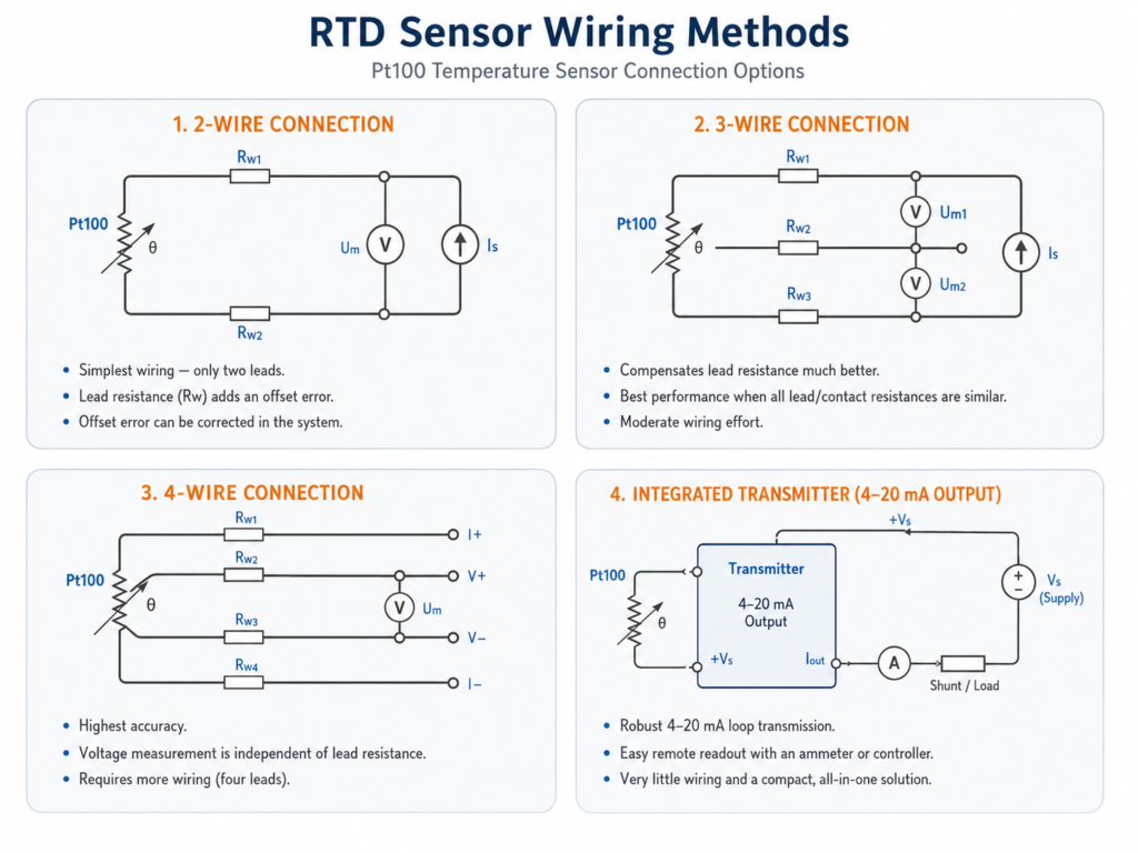
2-Wire Pt100 Connection
A 2-wire RTD connection uses only two wires.
This is the simplest method.
The transmitter measures the resistance of:
RTD element
plus
wire resistance
plus
contact resistance
Because the cable resistance is included in the measurement, the temperature reading can be higher than the real temperature.
2-Wire Advantages
Very little wiring required
Low cost
Simple installation
Useful for short cable lengths
Acceptable when high accuracy is not needed
2-Wire Disadvantages
Cable resistance creates offset error
Long cable length increases error
Contact resistance affects reading
Accuracy is limited
Compensation may be needed
For example, with some cable sizes, the cable can create an offset error of around 0.25°C per meter.
The exact value depends on conductor size, material, length, and connection quality.
When 2-Wire Is Acceptable
2-wire Pt100 wiring may be acceptable when:
Cable is short
Temperature accuracy is not critical
Measurement is used only for rough monitoring
System allows offset correction
Cost and simplicity are more important than precision
3-Wire Pt100 Connection
A 3-wire RTD connection is very common in industrial systems.
It uses three wires to reduce the effect of cable resistance.
The transmitter measures and compensates for the resistance of one lead wire.
For this to work well, the lead wires should have the same resistance.
3-Wire Advantages
Much better accuracy than 2-wire
Common industrial standard
Reasonable wiring cost
Good for medium cable lengths
Compensates most cable resistance error
3-Wire Disadvantages
Lead wires should be equal resistance
Bad terminals can still create errors
Not as perfect as 4-wire
Needs correct input module or transmitter setting
When 3-Wire Is Used
3-wire Pt100 wiring is often used for:
Process temperature measurement
Industrial machines
Heating systems
Cooling systems
Tanks
Pipelines
PLC analog temperature input modules
Temperature transmitters
For many industrial applications, 3-wire Pt100 is a good balance between accuracy and wiring effort.
4-Wire Pt100 Connection
A 4-wire RTD connection gives the best resistance measurement.
It uses separate wires for measurement current and voltage sensing.
The voltage measuring path carries almost no current.
Because of this, line resistance has almost no effect on the measurement.
4-Wire Advantages
Highest accuracy
Cable resistance has very little influence
Contact resistance changes have less effect
Best for precision measurements
Good for calibration and laboratory use
4-Wire Disadvantages
More wiring required
Higher cost
Needs compatible transmitter or input module
More terminals needed
When 4-Wire Is Used
4-wire Pt100 wiring is used when:
Accuracy is very important
Cable length is long
Measurement is used for calibration
Small temperature differences matter
Contact resistance may change
Laboratory or high-precision process measurement is needed
Integrated Temperature Transmitter With 4–20 mA Output
Instead of sending the raw Pt100 resistance or thermocouple millivolt signal over a long cable, many systems use a temperature transmitter.
A temperature transmitter converts the sensor signal into a standard industrial signal.
The most common output is:
4–20 mA
Some transmitters also support:
HART
IO-Link
Modbus
PROFINET
EtherNet/IP
0–10V
Relay or switching outputs
Why Use a Temperature Transmitter?
A transmitter improves signal transmission.
For example, a Pt100 signal can be affected by cable resistance.
A thermocouple signal is very small and sensitive to noise.
A transmitter can be installed near the sensor and send a stronger, more reliable 4–20 mA signal to the PLC.
Advantages of 4–20 mA Temperature Transmission
Reliable over long cable distances
Less sensitive to voltage drop and noise
Easy to read by PLC analog input
Can be checked with an ammeter or loop calibrator
Simple scaling in PLC
Broken wire can often be detected
Only two wires may be needed in loop-powered systems
Useful for industrial environments
Disadvantages of Using a Transmitter
Higher cost
Needs configuration
Can fail separately from the sensor
Adds another device to troubleshoot
Needs correct sensor type and range setting
Example 4–20 mA Scaling
A transmitter may be configured like this:
0°C = 4 mA
100°C = 20 mA
Then:
0°C = 4 mA
25°C = 8 mA
50°C = 12 mA
75°C = 16 mA
100°C = 20 mA
The PLC reads the current and scales it into temperature.
Head-Mounted and DIN-Rail Temperature Transmitters
Temperature transmitters are commonly available in two main formats:
Head-mounted transmitter
DIN-rail transmitter
Head-Mounted Transmitter
A head-mounted transmitter is installed inside the temperature sensor connection head.
This means the weak sensor signal is converted to 4–20 mA close to the measurement point.
This is useful for:
Reducing noise
Long cable runs
Compact installation
Field-mounted sensors
Process temperature probes
DIN-Rail Transmitter
A DIN-rail transmitter is installed inside the control cabinet.
The RTD or thermocouple cable runs from the sensor to the cabinet.
This is useful when:
Transmitters are grouped in one panel
Maintenance is easier in the cabinet
Field sensor heads are small
Configuration is done in the panel
Environment near the sensor is harsh
Configurable Temperature Transmitters
Many modern temperature transmitters are configurable.
They can be set for different input types, such as:
Pt100
Pt1000
Nickel RTD
Copper RTD
Type K thermocouple
Type J thermocouple
Type T thermocouple
Type N thermocouple
Type S thermocouple
Type R thermocouple
Type B thermocouple
They can also be configured for:
Measuring range
Output range
Sensor burnout behavior
Damping
Units
Cold junction compensation
Linearization curve
HART communication
Calibration offset
Correct configuration is very important.
If a transmitter is configured for the wrong sensor type, the temperature reading will be wrong.
Thermocouple Cold Junction Compensation
Thermocouples measure temperature difference, not absolute temperature by themselves.
The measuring junction is the hot end.
The terminals or transmitter input are the cold junction.
The transmitter must know the cold junction temperature to calculate the real process temperature.
This is called cold junction compensation.
If cold junction compensation is wrong, the temperature reading will be wrong.
Thermocouple Extension and Compensating Cable
Thermocouple cables are special.
If a thermocouple is extended, the extension cable must match the thermocouple type.
For example:
Type K thermocouple should use Type K extension or compensating cable.
If normal copper cable is used incorrectly, extra unwanted thermocouple junctions can be created.
This can distort the measurement.
This is one reason thermocouple installation often requires more care than RTD installation.
Process Connections for Temperature Sensors
Temperature sensors can be installed in many ways.
Common process connections include:
Threaded connection
Clamp connection
Flange connection
Weld-in connection
Compression fitting
Thermowell
Hygienic process connection
Sanitary connection
Pipe insertion fitting
Surface mounting
Cable probe
The correct connection depends on:
Pressure
Temperature
Medium
Hygienic requirement
Pipe size
Tank design
Mechanical strength
Cleaning process
Replacement needs
What Is a Thermowell?
A thermowell is a protective tube installed into the process.
The temperature sensor is inserted into the thermowell.
The thermowell protects the sensor from:
Pressure
Flow forces
Corrosion
Mechanical damage
Chemical attack
High velocity fluids
It also allows the sensor to be removed without opening the process.
This is useful in pressurized or hazardous systems.
Thermowell Advantages
Protects sensor
Allows replacement without draining the system
Useful for high pressure
Useful for aggressive media
Mechanical protection in pipelines
Longer sensor life
Thermowell Limitations
Slower response time
Must be correctly sized
Can create vibration risk in high flow
Poor contact can create measurement delay
Wrong insertion depth can cause bad readings
Temperature Sensor Response Time
Temperature sensors do not respond instantly.
Response time depends on:
Sensor design
Probe diameter
Thermowell size
Medium type
Flow speed
Insertion depth
Contact quality
Thermal mass
Mounting method
A thin probe in fast-moving liquid responds faster than a large probe inside a thick thermowell.
For process control, response time matters.
A slow sensor can make temperature control unstable or delayed.
Insertion Depth
Insertion depth is important.
If a sensor does not reach far enough into the pipe or tank, it may measure pipe wall temperature instead of process temperature.
General good practice:
The sensor tip should be in the actual flow or representative process area.
Bad installation examples:
Sensor tip too close to pipe wall
Sensor installed in dead leg
Sensor not inserted far enough
Sensor touching thermowell bottom incorrectly
Sensor not contacting thermowell properly
Sensor mounted where media is not mixed
Correct installation is just as important as sensor accuracy.
Common Temperature Units
Temperature can be shown in:
Celsius
Fahrenheit
Kelvin
In industrial automation, Celsius is common in Europe and many process industries.
Fahrenheit is common in some regions.
Kelvin is common in scientific and engineering calculations.
Temperature Unit Conversions
Celsius to Fahrenheit
°F = (°C × 9/5) + 32
Example:
100°C = 212°F
Fahrenheit to Celsius
°C = (°F – 32) × 5/9
Example:
212°F = 100°C
Celsius to Kelvin
K = °C + 273.15
Example:
25°C = 298.15 K
Kelvin to Celsius
°C = K – 273.15
Example:
298.15 K = 25°C
Temperature Sensor Output Signals
Common output signals include:
Raw Pt100 resistance
Raw Pt1000 resistance
Thermocouple millivolts
4–20 mA
0–10V
HART
IO-Link
Modbus
PROFINET
EtherNet/IP
The output type depends on the sensor, transmitter, and control system.
Raw RTD Signal
A raw RTD signal is resistance.
The PLC temperature input module or transmitter must be configured for the correct RTD type.
Example:
Pt100 3-wire
Pt1000 2-wire
Pt100 4-wire
Wrong input configuration causes wrong temperature values.
Raw Thermocouple Signal
A raw thermocouple signal is a small voltage.
The PLC input module or transmitter must be configured for the correct thermocouple type.
Example:
Type K
Type J
Type T
Wrong thermocouple type causes wrong temperature readings.
4–20 mA Signal
A transmitter converts temperature into current.
Example:
-50°C = 4 mA
150°C = 20 mA
The PLC must be scaled to the same range.
If the transmitter range and PLC range do not match, the displayed temperature will be wrong.
Example: Temperature Sensor Connected to PLC
A common setup looks like this:
Temperature probe installed in pipe.
Pt100 or thermocouple senses temperature.
Transmitter converts signal to 4–20 mA.
PLC analog input reads current.
PLC scales current into °C.
HMI displays temperature.
PLC controls heater, valve, or alarm.
Example scaling:
0°C = 4 mA
100°C = 20 mA
If PLC reads 12 mA:
12 mA is 50% of the 4–20 mA range.
So the temperature is:
50°C
Choosing the Right Temperature Sensor
Before choosing a temperature sensor, check:
Temperature range
Required accuracy
Response time
Process medium
Pressure
Chemical compatibility
Sensor length
Insertion depth
Process connection
Need for thermowell
Hygienic requirements
Vibration
Cable length
Signal type
PLC input type
Need for transmitter
Ambient conditions
Calibration requirement
Maintenance access
Use Pt100 or Pt1000 When:
You need good accuracy
You need stable measurement
Temperature range is moderate
Process control accuracy matters
Signal is going to a temperature transmitter or RTD input
You need repeatable measurement
You work in food, water, chemical, HVAC, or general process automation
Use Thermocouple When:
Temperature is very high
Fast response is needed
Sensor must be rugged
Application is furnace, oven, exhaust, boiler, or high-temperature process
Slightly lower accuracy is acceptable
Thermocouple input or transmitter is available
Use 4–20 mA Transmitter When:
Cable run is long
PLC has standard analog input
Noise immunity is important
You want easy troubleshooting
You need configurable range
You want to avoid RTD wire resistance problems
The sensor is far from the control cabinet
Common Temperature Measurement Problems
Common problems include:
Wrong sensor type
Wrong wiring method
2-wire cable resistance error
Bad Pt100 element
Broken thermocouple
Wrong thermocouple extension cable
Wrong transmitter range
Wrong PLC scaling
Bad cold junction compensation
Loose terminals
Moisture in connector
Poor insertion depth
Slow response from thermowell
Sensor not touching thermowell bottom
Sensor installed in dead zone
Electrical noise
Self-heating
Wrong accuracy class
Wrong units
Many temperature problems are not caused by a failed sensor.
They are caused by wiring, configuration, installation, or scaling mistakes.
Final Thoughts
Temperature sensors are simple in purpose but can be very different in technology.
The most common industrial temperature sensors are:
RTD sensors, such as Pt100 and Pt1000
Thermocouples
Temperature transmitters with 4–20 mA output
RTD sensors measure temperature by resistance change.
Thermocouples measure temperature by a small voltage created from two different metals.
Pt100 sensors have 100 Ω at 0°C.
Pt1000 sensors have 1000 Ω at 0°C.
Pt100 accuracy classes are defined by standards such as DIN/EN/IEC 60751.
For Pt100 wiring:
2-wire is simple but affected by cable resistance.
3-wire is common and compensates most cable resistance.
4-wire gives the best accuracy.
4–20 mA transmitters provide reliable signal transmission to PLC systems.
The key idea is:
Choose the temperature sensor based on temperature range, accuracy, process conditions, wiring distance, PLC input type, and installation environment.