Capacitive sensors can be brilliant.
They detect liquids through tank walls, see plastic parts that inductive sensors completely ignore, and work in places where mechanical switches would be a pain. But when they start acting strange? Oh, they can become annoying very quickly.
One minute the sensor works. Next minute it switches with nothing in front of it. Or it refuses to detect the material it detected yesterday. Or the LED turns on, but the PLC input sits there like a lazy cat and does absolutely nothing.
That is capacitive sensor troubleshooting in real life.
The good news is that most faults can be diagnosed with basic tools: a multimeter, wiring diagram, PLC input monitor, and a bit of patience. Not endless guessing. Not replacing parts until the machine feels sorry for you. Just a proper check, step by step.
What Can Go Wrong With a Capacitive Sensor?
A capacitive sensor detects changes in an electrical field. When a material enters the sensing area, the capacitance changes, and the sensor switches its output.
That sounds simple enough.
But because the sensor reacts to electrical field changes, it can also be affected by things around the target, not only the target itself. Moisture, dust, product buildup, wrong mounting, bad grounding, wrong sensitivity adjustment, damaged cable, incorrect sensor type, or even the tank wall can all create problems.
Common symptoms include:
- Sensor does not switch at all
- Sensor stays on all the time
- Sensor switches randomly
- Sensor detects empty tank as full
- Sensor detects full tank as empty
- Sensor LED works, but PLC input does not change
- Sensor only works when sensitivity is turned fully up
- Sensor works with water but not oil, powder, plastic, or granules
- Sensor works on the bench but fails on the real machine
- Sensor output flickers near the switching point
Classic automation fun. Small sensor, big headache.
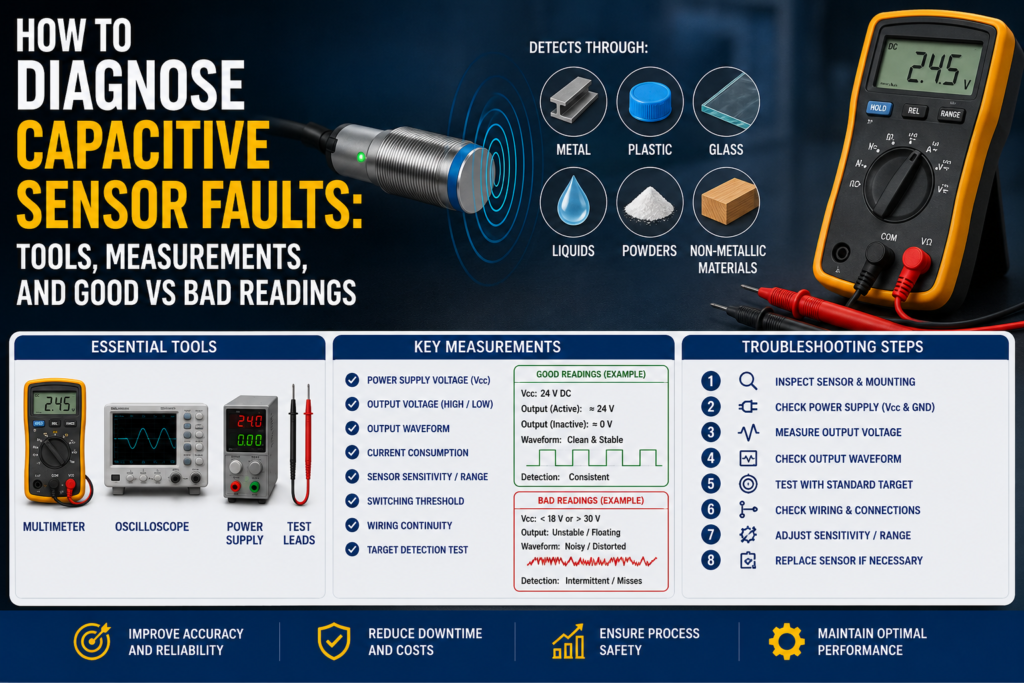
Tools Needed to Diagnose Capacitive Sensor Faults
You do not need a fancy laboratory setup for most checks. These tools are usually enough:
- Digital multimeter
- Wiring diagram or electrical schematic
- PLC online input monitor
- Small screwdriver for sensitivity adjustment
- Known test material, for example water, plastic, glass, metal, oil, powder, or the real product
- Grounded metal plate for testing, if needed
- Sensor tester, optional but useful
- Spare known-good sensor
- M8/M12 connector tester, if available
- Oscilloscope, optional for fast or unstable signals
- Cleaning cloth for sensor face
- Contact cleaner for connectors
The multimeter is the main tool. Simple, boring, and still one of the best fault-finding tools in the cabinet.
Step 1: Identify the Sensor Type
Before measuring anything, identify what type of capacitive sensor you have.
Check the sensor label or datasheet if possible. You need to know:
- Supply voltage: usually 10–30 V DC, 24 V DC, 230 V AC, or another range
- Output type: PNP, NPN, relay, two-wire, or analog
- Switching function: normally open or normally closed
- Mounting type: flush or non-flush
- Connection type: cable, M8 connector, M12 connector, terminal
- Sensitivity adjustment type: potentiometer, teach button, or fixed setting
This matters because the “good” reading depends on the sensor type.
For example, a PNP sensor usually sends positive voltage to the PLC input when active. An NPN sensor pulls the input down to 0 V when active. A two-wire sensor behaves differently again and may have leakage current even when “off.”
So first: know what you are testing.
Otherwise, you may start blaming a perfectly good sensor.
Step 2: Visual Inspection
Start with the obvious things. Yes, it feels basic. Do it anyway.
Check the sensor face. Is it covered with oil, dust, product residue, water, powder, glue, or condensation? Capacitive sensors can react to buildup, especially if the sensitivity is set high.
Check the cable. Look for crushed insulation, bent connector pins, loose M8/M12 plugs, broken cable glands, oil inside the connector, or cable damage near moving parts.
Check the mounting position. Is the sensor loose? Has it moved? Is it installed too deep in metal? Is a non-flush sensor mounted like a flush sensor? That one happens more often than people admit.
Good condition:
- Sensor face clean
- Cable undamaged
- Connector tight
- Sensor firmly mounted
- Correct mounting clearance around sensing face
- No heavy buildup around the sensor
Bad condition:
- Moisture on sensor face
- Thick product buildup
- Loose connector
- Sensor moved from position
- Damaged cable
- Sensor mounted too close to metal
- Wrong sensor type for mounting style
A capacitive sensor with dirt on its face may not be broken. It may just be “seeing” the dirt.
Step 3: Check Supply Voltage
For a standard three-wire DC sensor, the usual wiring is:
- Brown = +24 V DC
- Blue = 0 V DC
- Black = output signal
Measure between brown and blue.
In a normal 24 V DC system, a good reading is usually around 22–24 V DC.
Good supply reading:
| Test Point | Good Reading |
|---|---|
| Brown to blue | Around 22–24 V DC on a 24 V system |
| Voltage stability | Stable, not jumping around |
Bad supply reading:
| Reading | Possible Cause |
| 0 V DC | No supply, blown fuse, broken wire, wrong terminal |
| 5–15 V DC | Voltage drop, bad connection, overloaded supply |
| Voltage jumping | Loose wire, power supply issue, short circuit |
| Correct voltage at panel but not at sensor | Cable or connector fault |
No supply voltage means no proper sensor function. Do not replace the sensor before checking the power.
Simple rule. Saves money.
Step 4: Check the Sensor LED
Most capacitive sensors have an LED that shows output status or detection status.
Place the target material in front of the sensor and watch the LED. Then remove the target and watch again.
Good LED behavior:
- LED turns on when target is present
- LED turns off when target is removed
- LED is stable, not flickering
- Switching point is repeatable
Bad LED behavior:
- LED never turns on
- LED stays on all the time
- LED flickers with no target present
- LED changes when the cable is touched
- LED reacts to moisture, dirt, or nearby metal instead of the real target
If the LED behaves correctly but the PLC input does not, the problem may be wiring, PLC input type, input common, or a broken cable between the sensor and PLC.
If the LED itself behaves badly, look at sensor adjustment, target material, mounting, contamination, and sensor damage.
Step 5: Test With a Known Material
Capacitive sensors do not detect all materials equally.
Water is usually easy. Metal is usually easy. Oil, dry plastic, powders, and granules can be harder because their dielectric constant is lower.
So test the sensor with a known target material.
For example:
- Use water for liquid detection testing
- Use the real product if possible
- Use a plastic part if the sensor detects plastic
- Use a grounded metal plate to confirm basic sensor operation
- Use full and empty tank conditions for level sensors
Good result:
- Sensor detects the correct material at the expected distance
- Sensor switches repeatedly in the same position
- Sensitivity does not need to be turned fully up
Bad result:
- Sensor only detects when the target touches the face
- Sensor detects water but not the real product
- Sensor works only with sensitivity at maximum
- Sensor switches differently every time
- Sensor detects container wall instead of material inside
This is important: a sensor that detects water does not automatically prove it will detect oil, plastic, or dry powder reliably. Different material, different capacitance change.
Step 6: Check Sensitivity Adjustment
Many capacitive sensors have a small adjustment screw or teach function.
Sensitivity that is too low causes missed detection.
Sensitivity that is too high causes false detection.
And yes, the classic mistake is turning sensitivity all the way up and hoping for the best. It sometimes works for five minutes. Then condensation, dust, or a hand nearby triggers the sensor and everyone gets confused.
A better method:
- Put the machine in a safe condition.
- Remove the target material.
- Adjust the sensor so it is off with no target present.
- Add the real target material.
- Adjust until the sensor switches reliably.
- Remove and add the target several times.
- Leave some margin, not right on the switching edge.
Good adjustment:
- Sensor is off when no target is present
- Sensor switches on with the real target
- No flickering
- No false switching from nearby objects
- Stable operation after several test cycles
Bad adjustment:
- Sensor works only at maximum sensitivity
- Sensor detects the tank wall when empty
- Sensor flickers near the switching point
- Sensor changes state when moisture appears
- Sensor detects hands, tools, brackets, or product buildup
Capacitive sensors need adjustment with the real application in mind. Bench testing is useful, but the real machine is where the truth comes out.
Step 7: Measure the Output Signal
After checking supply voltage and LED behavior, measure the output.
For a common three-wire PNP sensor, measure between black and blue.
Good PNP readings:
| Sensor State | Output Reading |
| OFF | Around 0 V DC |
| ON | Around 22–24 V DC on a 24 V system |
Bad PNP readings:
| Reading | Possible Problem |
| Always 0 V | Sensor not detecting, no output, wrong wiring, damaged sensor |
| Always 24 V | Sensor stuck on, wrong adjustment, output shorted |
| 5–15 V DC | Bad output, overloaded output, wrong input wiring |
| Unstable voltage | Loose cable, flickering detection, moisture, bad connector |
For an NPN sensor, the behavior is different. An NPN output usually pulls the signal down to 0 V when active.
Good NPN behavior:
| Sensor State | Output Behavior |
| OFF | Output not pulled low |
| ON | Output close to 0 V DC |
Bad NPN behavior:
| Reading | Possible Problem |
| Never pulls low | Sensor not detecting, wrong wiring, damaged output |
| Always near 0 V | Output short, sensor stuck on, wrong adjustment |
| Floating/random voltage | Wrong input type, missing load, cable fault |
For a two-wire sensor, readings can be less straightforward because the sensor is connected in series with the load. A two-wire electronic sensor may have leakage current when off and a voltage drop when on.
Typical two-wire sensor checks:
| Condition | Expected Behavior |
| OFF | Small leakage current may still exist |
| ON | Load/PLC input should energize properly |
| Across sensor when ON | Some voltage drop may remain |
| Across sensor when OFF | Supply voltage may appear across sensor |
Bad signs on two-wire sensors:
- PLC input stays on because of leakage current
- Sensor cannot energize the input properly
- Load current is below the sensor’s minimum load requirement
- Voltage drop is too high
- Wrong AC/DC version installed
Two-wire sensors are convenient, but they can be tricky with some PLC inputs. Leakage current can make a high-impedance input behave strangely.
Step 8: Compare Sensor Output With PLC Input
This is one of the most important checks.
A sensor can switch perfectly, but the PLC may not see it.
Measure the signal at the sensor output. Then measure the same signal at the PLC input terminal. Finally, check the PLC input status online.
Good result:
- Sensor LED switches
- Output voltage changes correctly
- Same voltage reaches PLC input terminal
- PLC input LED changes
- PLC online input status changes
Bad result:
| Symptom | Possible Cause |
| Sensor output changes, PLC input does not | Broken wire, loose terminal, bad connector |
| Voltage reaches PLC, input LED off | Wrong input common, damaged input, wrong input type |
| PLC input LED on, program does not react | Wrong address, program logic issue, forcing, safety logic |
| Signal disappears under load | Weak sensor output, short circuit, input module issue |
Do not stop at the sensor LED. Follow the signal all the way to the PLC.
Many “bad sensors” are actually bad cables, wrong input commons, or program address mistakes.
Step 9: Check Flush or Non-Flush Mounting
Capacitive sensors are sensitive to mounting conditions.
Some sensors can be flush-mounted. Some cannot. If a non-flush capacitive sensor is installed inside metal or too close to surrounding material, the sensing field may be disturbed.
Good mounting:
- Sensor mounted according to datasheet
- Correct free space around sensing face
- Sensor face not buried too deep
- Target enters the sensing field clearly
- Metal brackets are not interfering
Bad mounting:
- Non-flush sensor installed flush in metal
- Sensor surrounded by metal too closely
- Sensor mounted too far from target
- Sensor sees wall or bracket instead of product
- Sensor position changed after vibration
If the sensor works in your hand but not when installed, mounting is a strong suspect.
That is a very common capacitive sensor problem.
Step 10: Check Tank Wall Detection
Capacitive sensors are often used for level detection through plastic or glass tank walls.
This can work very well, but only when the setup is right.
Things to check:
- Is the tank wall plastic, glass, or another suitable non-metallic material?
- Is the wall too thick?
- Is there buildup inside the tank?
- Is the liquid conductive or non-conductive?
- Is the product foam creating false detection?
- Is the sensor adjusted with the tank empty and full?
- Is the tank or medium grounded if needed?
Good level detection:
- Sensor off when tank is empty at that point
- Sensor on when liquid/product reaches the sensor
- Stable output with no flickering
- No false switching from wall thickness or residue
Bad level detection:
- Empty tank still detected as full
- Full tank not detected
- Sensor detects residue after tank drains
- Foam causes false switching
- Sensor works with water test but not real product
- Sensor behavior changes with humidity
A very common mistake is adjusting the sensor during a water test, then using it with oil, powder, glue, or another product. Water is easy. Other materials may not be.
Step 11: Check Conductive vs Non-Conductive Media
Conductive materials are usually easier for capacitive sensors to detect.
Examples:
- Water
- Milk
- Ink
- Acetone
- Metals
- Many water-based liquids
Non-conductive materials are often harder.
Examples:
- Oil
- Plastic
- Glass
- Wood
- Dry powder
- Granules
- Paper
Good reading with conductive media:
- Sensor detects from expected distance
- Stable switching
- Grounding improves detection if required
Bad reading with conductive media:
- No switching despite close target
- Poor grounding
- Signal changes when nearby metal is touched
- Sensor type not suitable for application
Good reading with non-conductive media:
- Sensor detects only when real material is present
- Sensitivity adjusted with real material
- Sensor has enough range for the application
Bad reading with non-conductive media:
- Sensor cannot detect unless material touches face
- Sensitivity must be at maximum
- Sensor switches randomly
- Sensor detects container wall or dirt instead of target
The lower the dielectric constant of the material, the harder it is to detect. This is why dry plastic or oil can give weaker detection than water.
Step 12: Check for Dirt, Moisture, and Product Buildup
Capacitive sensors can be sensitive to dirt and moisture.
A thin layer of water, oil, powder, or sticky product on the sensor face can change capacitance enough to affect switching.
Good condition:
- Sensor face clean
- No condensation
- No product buildup
- No conductive residue
- Sensor still switches correctly after cleaning
Bad condition:
- Sensor remains on after product is removed
- Sensor switches when wet
- Sensor changes state after cleaning
- False detection caused by residue
- Powder buildup reduces or increases sensitivity
Clean the sensing face and test again. If behavior changes after cleaning, contamination is part of the problem.
Very glamorous maintenance work, yes. Wiping sensors. But it works.
Step 13: Wiggle Test the Cable
Cable faults can imitate sensor faults perfectly.
With the sensor powered and in a safe condition, gently move the cable near:
- Sensor body
- Connector
- Cable gland
- Bend points
- Junction box
- Cable chain
- PLC terminal
Watch the LED, multimeter, and PLC input.
Good result:
- Signal remains stable while cable is moved
Bad result:
- LED flickers
- Output voltage jumps
- PLC input drops
- Sensor turns on/off when cable moves
If moving the cable changes the signal, suspect broken conductors, loose connector pins, oil inside the connector, damaged insulation, or a crushed cable.
Do not ignore cable faults. They love wasting time.
Step 14: Check for Electrical Noise
Capacitive sensors can sometimes be affected by electrical noise, especially if cables are routed badly.
Possible noise sources include:
- Variable frequency drives
- Motor cables
- Contactors
- Solenoid valves
- Welders
- Poor grounding
- Long unshielded sensor cables
- Bad 0 V reference
Good installation:
- Sensor cable separated from power cables
- Proper grounding
- Stable 24 V DC supply
- Cable shield used where required
- No random switching when motors start
Bad installation:
- Sensor cable tied together with motor cable
- Output flickers when VFD runs
- False switching when contactors energize
- Voltage spikes on supply
- Poor or missing 0 V reference
If the sensor only fails when a motor starts or a solenoid switches, do not immediately blame the sensor. Look at noise and grounding.
Good and Bad Readings Summary
Here is a practical quick-reference table.
| Test | Good Reading / Behavior | Bad Reading / Behavior |
| Supply voltage | 22–24 V DC on 24 V system | 0 V, low voltage, unstable voltage |
| PNP output OFF | Around 0 V DC | Voltage present when it should be off |
| PNP output ON | Around 22–24 V DC | 0 V, weak voltage, unstable voltage |
| NPN output ON | Close to 0 V DC | Does not pull low |
| Sensor LED | Clear ON/OFF switching | Flickering, always on, always off |
| PLC input | Matches sensor output | No change despite sensor switching |
| Empty tank | Sensor off | Sensor stays on |
| Full tank | Sensor on | Sensor does not switch |
| Clean sensor face | Stable operation | Operation changes after cleaning |
| Cable movement | No signal change | Signal flickers or drops |
| Sensitivity setting | Stable with some margin | Only works at maximum setting |
| Mounting | Correct flush/non-flush setup | Sensor field disturbed by metal |
| Test material | Detects real product reliably | Detects water only, not actual product |
A good capacitive sensor signal should be stable and repeatable. Not “maybe.” Not “sometimes.” Stable.
Common Faults and Likely Causes
| Symptom | Likely Cause |
| Sensor does not switch | No supply, wrong sensitivity, wrong material, faulty sensor |
| Sensor always on | Sensitivity too high, dirt, moisture, detected wall, stuck output |
| Sensor flickers | Edge of sensing range, vibration, bad adjustment, unstable product |
| LED works but PLC input does not | Wiring fault, wrong input common, damaged PLC input |
| Sensor detects empty tank | Sensitivity too high, wall detected, residue, condensation |
| Sensor does not detect full tank | Wall too thick, low dielectric material, poor adjustment |
| Works with water but not oil | Oil has lower dielectric constant |
| Works on bench but not installed | Wrong mounting, metal interference, distance issue |
| Works only when cable moved | Broken cable or connector fault |
| New sensor does not work | Wrong PNP/NPN, wrong NO/NC, wrong voltage type |
When the Sensor Is Not the Real Problem
Sometimes the sensor is innocent.
A capacitive sensor may be blamed when the real issue is product behavior, tank residue, bad grounding, PLC wiring, incorrect sensitivity, or mechanical position.
Before replacing the sensor, confirm:
- Supply voltage is correct
- Sensor type matches the PLC input
- Output switches correctly
- Signal reaches the PLC
- PLC input status changes
- Sensor is adjusted with the real material
- Mounting style is correct
- Sensor face is clean
- Target material is suitable for capacitive detection
Replacing the sensor without checking these basics can lead to the famous maintenance loop: new sensor, same problem, more confusion.
Nobody enjoys that.
Final Troubleshooting Checklist
Use this checklist when diagnosing capacitive sensor problems:
- Identify sensor type, voltage, output, and mounting style.
- Inspect sensor face, cable, connector, and mounting.
- Measure supply voltage.
- Check LED operation.
- Test with a known material.
- Adjust sensitivity correctly.
- Measure output voltage.
- Compare output signal with PLC input.
- Check PLC online status.
- Verify tank wall thickness and material.
- Check conductive vs non-conductive media behavior.
- Clean the sensor face.
- Wiggle test the cable.
- Check for electrical noise and grounding problems.
- Replace the sensor only after confirming the basics.
Final Thoughts
Capacitive sensors are powerful because they can detect materials that other sensors cannot: liquids, plastics, glass, wood, powders, granules, and more. But they are also sensitive to the environment around them.
That is both their strength and their weakness.
To diagnose faults properly, start with the simple checks. Supply voltage. LED. Output signal. PLC input. Cable. Mounting. Sensitivity. Then look at the material itself: is it conductive, non-conductive, wet, dry, grounded, low dielectric, behind a thick wall, or leaving residue?
Most capacitive sensor problems are not mysterious. They are usually caused by wrong adjustment, dirt, moisture, bad mounting, unsuitable material, wiring faults, or PLC input mismatch.
Not glamorous. But very fixable.
And as with most automation troubleshooting, the best advice is this: follow the signal, don’t follow guesses.