Ultrasonic sensors are usually reliable.
Until they aren’t.
A conveyor stops because the sensor doesn’t see a box. A tank level reading jumps around like it had too much coffee. A transparent bottle passes through and the PLC input never changes. Or the sensor LED flashes nicely, but the machine still says “object missing.”
Very fun. Not really.
The good thing is that ultrasonic sensor faults can usually be diagnosed with normal maintenance tools. A multimeter, PLC input monitor, wiring diagram, and a bit of common sense will find most problems. Sometimes the sensor is actually faulty. But many times the real issue is mounting, target angle, blind zone, wrong teach setting, interference, cable damage, or a PLC input mismatch.
So before replacing the sensor, follow the signal.
What Can Go Wrong With an Ultrasonic Sensor?
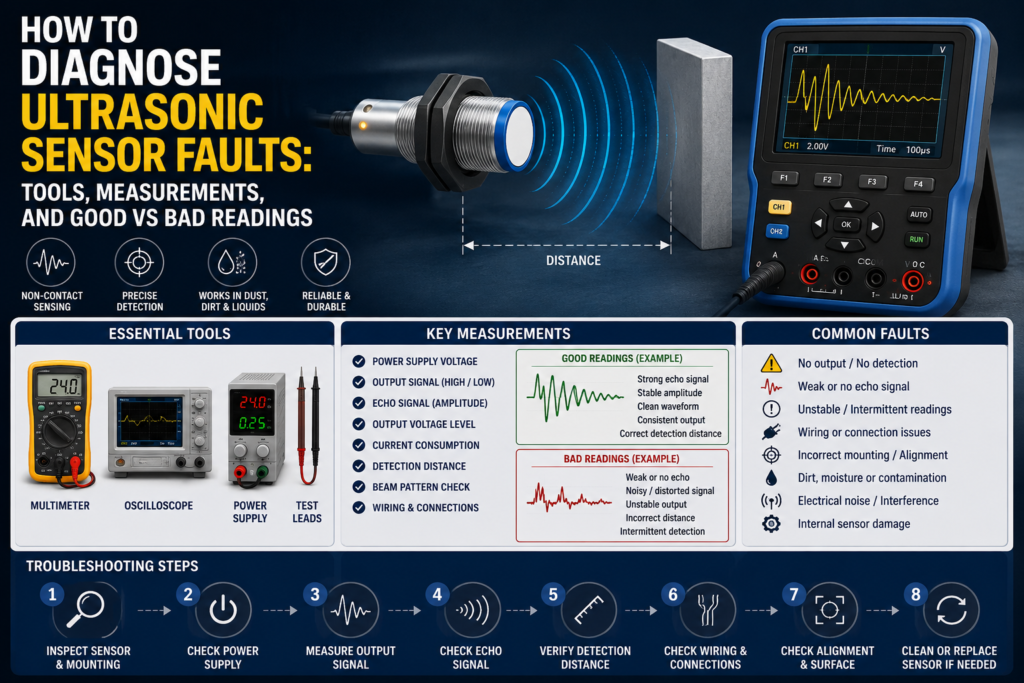
Ultrasonic sensors detect objects or measure distance by sending high-frequency sound waves and receiving the echo. If the echo is strong, clean, and arrives within the expected time, the sensor can switch an output or provide an analog distance value.
That sounds simple.
But in real applications, many things can disturb that echo.
Common symptoms include:
- Sensor does not detect the object
- Sensor detects only sometimes
- Sensor output stays on all the time
- Sensor output stays off all the time
- Analog distance value jumps up and down
- Sensor detects the wrong object
- PLC input does not change
- Sensor LED works, but PLC signal is missing
- Sensor detects the background instead of the target
- Sensor fails when another ultrasonic sensor is nearby
- Level reading is unstable in a tank or hopper
- Sensor works on the bench but not on the machine
Classic factory problem. Small sensor, big stop.
Tools Needed to Diagnose Ultrasonic Sensor Faults
You do not need expensive equipment for most ultrasonic sensor checks.
Useful tools include:
- Digital multimeter
- Wiring diagram or electrical schematic
- PLC online input monitor
- Sensor datasheet
- Small screwdriver for potentiometer adjustment
- Teach-in tool or remote teach wire, if used
- Known good test target, preferably flat and solid
- Tape measure or ruler
- Spare known-good sensor
- Sensor tester, optional
- Oscilloscope, optional for unstable or fast signals
- IO-Link master or software, if the sensor supports IO-Link
- Cleaning cloth
- Contact cleaner for connectors
The multimeter is still the main tool. Not fancy, but it tells you whether voltage is actually there instead of just “probably there.”
And “probably” is where troubleshooting goes to die.
Step 1: Identify the Sensor Type
Before measuring, identify what kind of ultrasonic sensor you have.
Common types include:
- Ultrasonic proximity sensor
- Ultrasonic retro-reflective sensor
- Ultrasonic through-beam sensor
- Ultrasonic distance sensor
- Ultrasonic level sensor
Also check the output type:
- PNP digital output
- NPN digital output
- Normally open output
- Normally closed output
- Two-wire output
- Relay output
- Analog voltage output, such as 0–10 V
- Analog current output, such as 4–20 mA
- IO-Link or digital communication
This matters because good readings depend on the sensor type.
A PNP output should usually send positive voltage to the PLC input when active. An NPN output normally pulls the signal down to 0 V when active. A 4–20 mA distance sensor will not behave like a simple on/off sensor at all.
So first, know what you are testing.
Otherwise, you may call a good sensor bad. Happens all the time.
Step 2: Visual Inspection
Start with the boring stuff. It works more often than people admit.
Check the sensor face. Is it dirty, wet, cracked, covered with oil, dust, glue, powder, or product buildup? Ultrasonic sensors are more tolerant of dirt than optical sensors, but that does not mean they enjoy being buried under half a factory.
Check the connector. M8 and M12 connectors can look connected but still be loose. Moisture inside the connector can also create strange intermittent faults.
Check the cable. Look for crushed insulation, broken cable glands, sharp bends, cable chain damage, oil damage, or vibration damage.
Check the mounting bracket. If the sensor has moved even a little, the sound cone may no longer point at the target properly.
Good condition:
- Sensor face is clean
- Cable is not damaged
- Connector is tight and dry
- Sensor is firmly mounted
- Sensor is aimed correctly
- No obvious obstruction in the sound cone
Bad condition:
- Dirty or damaged sensor face
- Loose connector
- Water or oil inside connector
- Sensor bracket loose
- Cable crushed or pulled
- Sensor pointing at the wrong angle
- Metal bracket or machine frame inside sensing area
A loose bracket can make a sensor look faulty when the sensor itself is completely fine.
Annoying, but true.
Step 3: Check Supply Voltage
For many three-wire DC sensors, the usual wiring is:
- Brown = +24 V DC
- Blue = 0 V DC
- Black = output signal
Always confirm with the sensor datasheet, because not every sensor follows the same wiring.
Measure between brown and blue.
In a normal 24 V DC system, a good reading is usually around 22–24 V DC.
Good supply readings:
| Test Point | Good Reading |
|---|---|
| Brown to blue | Around 22–24 V DC on a 24 V system |
| Supply stability | Voltage remains stable |
| Voltage under load | Does not drop when sensor switches |
Bad supply readings:
| Reading | Possible Cause |
| 0 V DC | No supply, blown fuse, broken wire, wrong terminal |
| 5–15 V DC | Voltage drop, bad connection, overloaded power supply |
| Voltage jumping | Loose wire, faulty power supply, intermittent short |
| Correct voltage in panel but not at sensor | Cable or connector fault |
No power means no real diagnosis yet. Fix the supply first.
Simple. Boring. Necessary.
Step 4: Check the Sensor LED
Most ultrasonic sensors have at least one LED. Some show output status. Some show echo quality. Some show teach status or signal strength.
Place the target inside the sensing range and watch the LED. Then remove the target and watch again.
Good LED behavior:
- LED changes state when target is present
- LED returns to normal when target is removed
- LED does not flicker when target is stationary
- Signal strength LED, if available, shows stable detection
- Teach LED confirms successful setup
Bad LED behavior:
- LED never turns on
- LED stays on all the time
- LED flickers constantly
- LED changes only when cable is moved
- LED shows weak signal
- Teach function fails
- LED reacts to background instead of target
If the LED behaves correctly but the PLC input does not change, the sensor may be fine. The fault may be in the cable, terminal, PLC input common, input module, or program.
If the LED itself behaves badly, look at target position, mounting angle, sensing range, blind zone, dirt, interference, or sensor damage.
Step 5: Check the Blind Zone
Ultrasonic sensors usually have a blind zone near the sensing face.
This is the area where the sensor cannot detect properly because it has just transmitted a sound pulse and needs time to switch into receive mode.
If the object is too close, the sensor may not see it.
Good setup:
- Target is outside the blind zone
- Target is inside the usable sensing range
- Sensor switches reliably at the required distance
Bad setup:
- Target is too close to sensor face
- Sensor misses object at close range
- Output flickers near minimum distance
- Sensor works only when target is moved farther away
This is a common mistake. People mount the sensor too close and then wonder why a “short distance” sensor does not detect the object.
Too close can be wrong.
Step 6: Test With a Known Good Target
Use a known target to check basic sensor operation.
A good test target is usually:
- Flat
- Hard
- Solid
- Large enough
- Positioned perpendicular to the sensor axis
A metal plate, flat plastic plate, or solid box can work well for basic testing. The target should be larger than the minimum target size recommended for the sensor range.
Move the target slowly toward and away from the sensor.
Good result:
- Sensor detects the target at a repeatable distance
- LED switches clearly
- Output signal changes correctly
- No flickering when target is stationary
Bad result:
- Sensor only detects at very short distance
- Sensor does not detect at all
- Sensor flickers
- Sensor detects different distances every time
- Sensor detects background instead of target
If the sensor works with a flat test target but not with the real object, the issue may be the real object’s shape, size, angle, speed, or surface material.
That does not automatically mean the sensor is faulty. It may mean the application is difficult.
Step 7: Check Target Surface and Angle
Ultrasonic sensors need the sound echo to return to the receiver.
Flat hard surfaces reflect sound well. Soft, rough, angled, curved, or porous surfaces may reflect weakly or send the sound away from the sensor.
Good target conditions:
- Surface is reasonably hard
- Target is large enough
- Target is not too angled
- Sound can reflect back toward the sensor
- Target remains inside the sound cone
Bad target conditions:
- Target is foam, cotton, cloth, felt, or porous material
- Target is too small
- Target is strongly tilted
- Target is round and reflects sound away
- Target moves too fast for the sensor response
- Target surface changes from piece to piece
Common sound-absorbing materials include:
- Foam rubber
- Cotton
- Wool
- Cloth
- Felt
- Very porous materials
A sensor that easily detects a cardboard box may struggle with foam. A sensor that detects a flat bottle front may miss the same bottle at an angle.
Same sensor. Different echo.
Step 8: Measure Digital Output Signal
For a common three-wire PNP sensor, measure between black and blue.
When the sensor is off, you usually expect around 0 V DC.
When the sensor is on, you usually expect close to supply voltage, for example 22–24 V DC on a 24 V system.
Good PNP readings:
| Sensor State | Output Reading |
| OFF | Around 0 V DC |
| ON | Around 22–24 V DC |
Bad PNP readings:
| Reading | Possible Problem |
| Always 0 V | No detection, no supply, damaged output, wrong wiring |
| Always 24 V | Sensor stuck on, wrong teach setting, output shorted |
| 5–15 V DC | Overloaded output, bad connection, wrong input wiring |
| Unstable voltage | Flickering echo, cable fault, interference, poor mounting |
For an NPN sensor, the output usually pulls the input down to 0 V when active.
Good NPN behavior:
| Sensor State | Output Behavior |
| OFF | Output not pulled low |
| ON | Output close to 0 V DC |
Bad NPN behavior:
| Reading | Possible Problem |
| Never pulls low | Sensor not detecting, damaged output, wrong wiring |
| Always near 0 V | Output shorted, sensor stuck on |
| Floating/random voltage | Missing load, wrong input type, cable problem |
Always check the exact wiring and sensor type. Guessing PNP/NPN logic is a fantastic way to waste an hour.
Ask me how I know.
Step 9: Check Analog Output Readings
Ultrasonic distance and level sensors often use analog outputs.
Common analog signals include:
- 0–10 V
- 1–10 V
- 4–20 mA
- 0–20 mA
The output value should change smoothly as the target distance changes.
For a 0–10 V sensor:
| Condition | Good Reading |
| Target at minimum taught distance | Close to 0 V or programmed low value |
| Target at maximum taught distance | Close to 10 V or programmed high value |
| Target moving slowly | Voltage changes smoothly |
| Target stationary | Voltage remains stable |
Bad 0–10 V readings:
| Reading | Possible Problem |
| Always 0 V | No detection, no supply, wrong wiring, output fault |
| Always 10 V | Out of range, wrong teach setting, output saturated |
| Random jumping voltage | Weak echo, interference, moving surface, cable noise |
| Voltage does not match distance | Wrong scaling, wrong teach range, sensor configuration issue |
For a 4–20 mA sensor:
| Condition | Good Reading |
| Target at minimum taught distance | Around 4 mA, depending on scaling |
| Target at maximum taught distance | Around 20 mA, depending on scaling |
| Target moving slowly | Current changes smoothly |
| Target stationary | Current stays stable |
Bad 4–20 mA readings:
| Reading | Possible Problem |
| 0 mA | Open circuit, no supply, broken wire |
| Below 4 mA | Fault condition, wrong wiring, sensor error |
| Always 4 mA | Target at minimum, no change, scaling issue |
| Always 20 mA | Target at maximum, out of range, saturated output |
| Jumping current | Weak echo, turbulence, foam, interference, bad cable |
For level sensors, the analog output may increase or decrease depending on whether the sensor is configured for distance or level.
Important difference:
Distance output means farther surface = higher value.
Level output may mean higher material level = higher value.
Do not mix those up. It makes troubleshooting very confusing, very fast.
Step 10: Compare Sensor Signal With PLC Input
A sensor can work perfectly and still not be seen by the PLC.
Check the signal in three places:
- At the sensor connector
- At the PLC input terminal
- In the PLC online input monitor
Good result:
- Sensor LED changes
- Output voltage changes at the sensor
- Same voltage reaches the PLC input
- PLC input LED changes
- PLC online status changes
Bad result:
| Symptom | Possible Cause |
| Output changes at sensor but not at PLC | Broken cable, loose terminal, connector fault |
| Voltage reaches PLC but input LED off | Wrong input common, wrong sensor type, damaged input |
| PLC LED on but program does not react | Wrong address, forcing, program logic, safety condition |
| Signal disappears under load | Short circuit, overloaded output, faulty input card |
Do not stop at the sensor LED. The machine does not care about the LED. The PLC signal is what matters.
Well, the LED helps. But it doesn’t run the sequence.
Step 11: Check Teach-In or Range Adjustment
Many ultrasonic sensors have adjustable sensing ranges.
Adjustment may be done by:
- Potentiometer
- Teach-in button
- Remote teach wire
- IO-Link
- Software configuration
Wrong teach settings can create very strange faults. The sensor may ignore the object, detect the background, or switch in the wrong area.
Good adjustment:
- Detection range matches the real target position
- Background is not detected as the target
- Object is detected reliably inside the set range
- Output changes at the correct distance
- Sensor has some margin, not right on the edge
Bad adjustment:
- Sensor detects background instead of object
- Sensor ignores target because range is too short
- Sensor switches too early or too late
- Sensor works only with perfect object position
- Analog output scaling does not match PLC expectation
After adjusting, test with the real object. Not only with your hand.
Hands are not production parts. Even if we use them too often during testing.
Step 12: Check Mounting and Sound Cone
Ultrasonic sensors emit sound in a cone shape, not a thin straight line.
That means objects beside the target can sometimes create reflections. Machine frames, walls, guides, brackets, guards, or tank walls may interfere.
Good mounting:
- Sensor points directly at the target
- Target is inside the main sound cone
- No unwanted object inside sensing area
- Sensor is not too close to side walls
- Bracket is stable
- Sensor is outside blind zone
- Target reflects sound back toward sensor
Bad mounting:
- Sensor angled poorly
- Target is near edge of sound cone
- Side wall reflects sound
- Machine bracket inside sensing area
- Sensor vibrates
- Sensor is too close to target
- Background reflection is stronger than target echo
If the sensor detects something when the target is not present, check what else is inside the sound cone.
The sensor might not be lying. It might be detecting exactly what you accidentally showed it.
Step 13: Check for Mutual Interference
If multiple ultrasonic sensors are installed close together, they may interfere with each other.
One sensor can hear another sensor’s ultrasonic pulse or echo. That can cause false switching, unstable analog readings, or random distance values.
Signs of interference:
- Sensor works alone but fails when others are powered
- Analog value jumps when nearby sensor operates
- False detections happen at regular intervals
- Detection improves when one sensor is disconnected
- Several sensors face the same area
Good solutions:
- Increase distance between sensors
- Change sensor angles
- Use synchronization inputs
- Trigger sensors one at a time
- Use PLC time slots
- Use sound-absorbing barriers
- Avoid overlapping sound cones
- Use IO-Link or sensor settings if available
Bad setup:
- Several sensors facing each other
- Sensors mounted too close
- Sensors firing at the same time
- Overlapping detection cones
- No synchronization in tight spaces
If three ultrasonic sensors are all “shouting” at the same time, one of them may hear the wrong echo. Sensors are clever, not psychic.
Step 14: Check Through-Beam Ultrasonic Sensors
Through-beam ultrasonic sensors use a separate emitter and receiver.
The emitter sends sound. The receiver listens. When an object blocks the sound beam, the output changes.
Checks for through-beam sensors:
- Is the emitter powered?
- Is the receiver powered?
- Are emitter and receiver aligned?
- Is the beam blocked by dirt, product, or bracket?
- Is the sensitivity set correctly?
- Does the receiver LED show signal strength?
- Does the output change when beam is interrupted?
Good readings and behavior:
| Test | Good Result |
| Emitter supply | Correct supply voltage |
| Receiver supply | Correct supply voltage |
| Beam clear | Receiver detects signal |
| Beam blocked | Output changes state |
| Alignment | Stable signal strength LED |
Bad readings and behavior:
| Symptom | Possible Cause |
| Receiver never sees emitter | Misalignment, no emitter power, wrong distance |
| Output always blocked | Beam blocked, emitter failed, receiver failed |
| Signal flickers | Poor alignment, vibration, weak signal |
| Works only close range | Low power setting, wrong sensor pair, contamination |
| No output change | Wrong wiring, damaged output, PLC input issue |
Alignment is everything with through-beam sensors. A tiny angle error can make the receiver lose the signal.
Step 15: Check Retro-Reflective Ultrasonic Sensors
Retro-reflective ultrasonic sensors use a fixed reflector.
The sensor expects an echo from the reflector. When an object enters the sensing area and changes or blocks that echo, the output switches.
Checks for retro-reflective sensors:
- Is the reflector fixed and stable?
- Is the reflector large enough?
- Does the reflector reflect sound well?
- Is the distance to reflector taught correctly?
- Does the object fully interrupt the sound cone?
- Is the object too small?
- Is the reflector dirty, tilted, or moved?
Good behavior:
| Condition | Good Result |
| No object present | Sensor sees reflector |
| Object present | Output changes |
| Reflector position | Stable and repeatable |
| Object size | Large enough to interrupt sound path |
Bad behavior:
| Symptom | Possible Cause |
| Sensor always detects object | Reflector missing, moved, dirty, wrong teach |
| Sensor never detects object | Object too small, does not block cone |
| Output flickers | Weak reflector echo, vibration, unstable mounting |
| Works after re-teach only briefly | Reflector or sensor moving |
Retro-reflective ultrasonic sensors are good for difficult objects, but the reflector setup must be solid. A loose reflector is basically a fault generator.
Step 16: Check Level Measurement Problems
Ultrasonic level sensors can be affected by the condition of the material surface.
For liquid tanks, check:
- Foam
- Vapor
- Turbulence
- Agitation
- Condensation on sensor face
- Wrong mounting angle
- Sensor too close to tank wall
- Filling stream crossing the beam
For powders, granules, and bulk materials, check:
- Dust clouds
- Uneven surface
- Cone-shaped material pile
- Very soft or absorbent material
- Sensor aimed at sloped surface
- Buildup on sensor face
Good level reading:
- Analog value is stable when level is stable
- Value changes smoothly as level changes
- Sensor does not jump to empty/full randomly
- PLC scaling matches sensor range
Bad level reading:
- Value jumps up and down
- Sensor loses echo
- Sensor reads tank wall
- Sensor reads filling stream
- Foam gives false level
- Dust blocks or weakens echo
- Condensation causes unstable measurement
A tank may be full, but if the surface is foamy or angled badly, the sensor may not get a clean echo. Again, not magic. Echo quality matters.
Step 17: Wiggle Test the Cable
Cable faults are sneaky.
With the machine safe, activate the sensor and gently move the cable near:
- Sensor connector
- Cable gland
- Bend points
- Cable chain
- Junction box
- PLC terminal
Watch the sensor LED, output voltage, and PLC input.
Good result:
- Signal stays stable
Bad result:
- LED flickers
- Voltage jumps
- PLC input turns on/off
- Analog signal spikes
- Sensor loses power
If movement changes the signal, suspect broken conductors, loose pins, water in connector, bad terminal, or damaged cable.
A bad cable can make a good sensor look drunk.
Step 18: Check Electrical Noise
Ultrasonic sensors can be affected by electrical noise, especially analog outputs.
Noise sources include:
- Variable frequency drives
- Motor cables
- Contactors
- Solenoid valves
- Welders
- Long unshielded cables
- Poor grounding
- Bad 0 V reference
- Shared supply with noisy loads
Good installation:
- Sensor cable separated from motor cables
- Stable 24 V DC supply
- Proper grounding
- Shielded cable used where needed
- Current output used for long cable runs
- Analog signal stable in PLC
Bad installation:
- Sensor cable tied to VFD output cable
- Analog value jumps when motor starts
- Output flickers when solenoid switches
- 0 V reference unstable
- Poor shielding or grounding
- Long voltage signal cable in noisy area
If the sensor fails only when a motor starts, look at noise before replacing the sensor.
Good and Bad Readings Summary
Here is a practical quick-reference table.
| Test | Good Reading / Behavior | Bad Reading / Behavior |
| Supply voltage | 22–24 V DC on 24 V system | 0 V, low voltage, unstable voltage |
| PNP output OFF | Around 0 V DC | Voltage present when it should be off |
| PNP output ON | Around 22–24 V DC | 0 V, weak voltage, unstable voltage |
| NPN output ON | Close to 0 V DC | Does not pull low |
| 0–10 V analog | Smooth value according to distance | Jumping, stuck at 0 V or 10 V |
| 4–20 mA analog | Smooth value according to distance | 0 mA, below 4 mA, stuck, jumping |
| Sensor LED | Clear and stable switching | Flickering, always on, always off |
| PLC input | Matches sensor output | No change despite sensor signal |
| Target detection | Repeatable at same distance | Random or weak detection |
| Blind zone | Target outside minimum range | Target too close to sensor |
| Sound cone | Only target detected | Bracket/wall/background detected |
| Cable movement | No signal change | Signal flickers or drops |
| Multiple sensors | Stable operation | Interference or false echoes |
A good ultrasonic sensor signal should be stable, repeatable, and logical. If the value is jumping around while nothing is moving, something is wrong.
Maybe not the sensor itself. But something.
Common Faults and Likely Causes
| Symptom | Likely Cause |
| Sensor does not switch | No power, target out of range, blind zone, weak echo |
| Sensor always on | Background detected, wrong teach setting, output short |
| Sensor flickers | Weak echo, edge of range, vibration, interference |
| LED switches but PLC does not | Wiring fault, wrong input type, damaged PLC input |
| Analog value jumps | Poor echo, turbulence, noise, interference |
| Sensor detects wrong object | Sound cone hitting bracket, wall, or background |
| Works with flat target but not real object | Target too small, angled, soft, or sound-absorbing |
| Works alone but not with other sensors | Mutual ultrasonic interference |
| Through-beam receiver unstable | Misalignment, weak signal, vibration |
| Level reading unstable | Foam, dust, turbulence, condensation, wrong mounting |
| New sensor does not work | Wrong PNP/NPN, wrong voltage, wrong teach setup |
When the Sensor Is Not the Real Problem
Not every ultrasonic sensor fault is actually a sensor fault.
The sensor may be fine, but the application may be wrong. Maybe the object is too close. Maybe the sound reflects away. Maybe the PLC input common is missing. Maybe another sensor is interfering. Maybe the tank has foam. Maybe the target is smaller than expected. Maybe someone moved the bracket by 5 mm and said nothing.
That last one is a classic.
Before replacing the sensor, confirm:
- Supply voltage is correct
- Sensor type matches the wiring and PLC input
- Target is outside the blind zone
- Target is inside the sensing range
- Sensor LED behaves correctly
- Output signal changes correctly
- Signal reaches the PLC input
- PLC online status changes
- Sensor is aimed correctly
- Target reflects sound well enough
- No nearby sensor is causing interference
- Teach-in or range setting is correct
If all of these are good and the sensor still behaves badly, then yes, the sensor may be faulty.
But check the basics first.
Final Troubleshooting Checklist
Use this checklist for ultrasonic sensor diagnosis:
- Identify the sensor type and output type.
- Inspect the sensor face, cable, connector, and bracket.
- Measure supply voltage.
- Check the sensor LED or signal strength indicator.
- Confirm the target is outside the blind zone.
- Test with a flat known-good target.
- Check target size, surface, and angle.
- Measure digital output voltage.
- Measure analog output, if used.
- Compare sensor signal with PLC input.
- Check PLC online status.
- Verify teach-in or range settings.
- Check the sound cone for unwanted reflections.
- Check for mutual interference between sensors.
- Check through-beam alignment, if applicable.
- Check reflector setup, if retro-reflective.
- Inspect level measurement conditions: foam, dust, vapor, turbulence.
- Wiggle test the cable.
- Check electrical noise and grounding.
- Replace the sensor only after confirming the basics.
Final Thoughts
Ultrasonic sensors are powerful because they can detect objects that optical sensors may struggle with: transparent materials, glossy surfaces, changing colors, liquids, powders, granules, and more.
But ultrasonic detection depends on sound. And sound has rules.
The target must reflect enough echo. The sensor must be aimed correctly. The object must not be inside the blind zone. Other sensors should not interfere. The output must reach the PLC. Analog signals must be scaled correctly. And if you are measuring level, the surface condition matters a lot.
Most ultrasonic sensor problems come from simple causes: no power, wrong output type, poor mounting, weak echo, wrong teach setting, cable damage, electrical noise, or interference from another sensor.
So don’t guess straight away.
Measure the supply. Watch the LED. Check the output. Follow the signal to the PLC. Test with a real target. Look at the sound cone. Then decide whether the sensor is actually bad.
Troubleshooting is much easier when you follow the echo instead of chasing ghosts.