Inductive sensors are everywhere in automation.
You see them on conveyors, CNC machines, presses, packaging lines, rotating shafts, machine guards, fixtures, cylinders, tool changers, and hundreds of other places where a metal part needs to be detected without touching it.
They are not fancy-looking devices. Usually just a small threaded cylinder or rectangular block with a cable or connector. But that little sensor can stop a whole production line if it does not switch at the right moment.
And honestly, that is what makes inductive sensors so important. They are simple, robust, fast, and reliable — as long as they are selected and installed correctly.
What Is an Inductive Sensor?
An inductive sensor is a non-contact sensor used to detect metallic objects.
It does not need physical contact with the target. Instead, it creates an electromagnetic field in front of its sensing face. When a metal object enters this field, the sensor detects the change and switches its output or changes its measured signal.
In industrial automation, inductive sensors are commonly used to detect:
- Metal part presence
- Machine position
- End positions
- Gear teeth
- Rotating shafts
- Tool presence
- Metal objects on conveyors
- Distance to metallic targets
There are two main types:
- Inductive proximity sensors
- Inductive distance sensors
An inductive proximity sensor usually gives a simple digital signal: object present or object not present.
An inductive distance sensor gives a measurement value related to the distance between the sensor and the metal target. This value can be analog, digital, or transmitted through a communication interface.
So, proximity sensors answer: “Is the metal there?”
Distance sensors answer: “How far away is the metal?”
Small difference. Big difference in application.
How Does an Inductive Sensor Work?
An inductive sensor works by generating an electromagnetic field from its active sensing face.
Inside the sensor, a coil is part of an oscillator circuit. This oscillator produces a high-frequency alternating electromagnetic field. When no metal object is nearby, the oscillator works normally.
When a metallic object enters the sensing field, eddy currents are induced in the metal. These eddy currents absorb energy from the oscillator. The sensor electronics detect this change.
In a digital inductive proximity sensor, this change causes the output to switch.
In an inductive distance sensor, the change is evaluated as a measurement signal related to target distance.
In plain language:
The sensor creates a field.
Metal enters the field.
The field changes.
The sensor reacts.
Simple idea, but very useful.
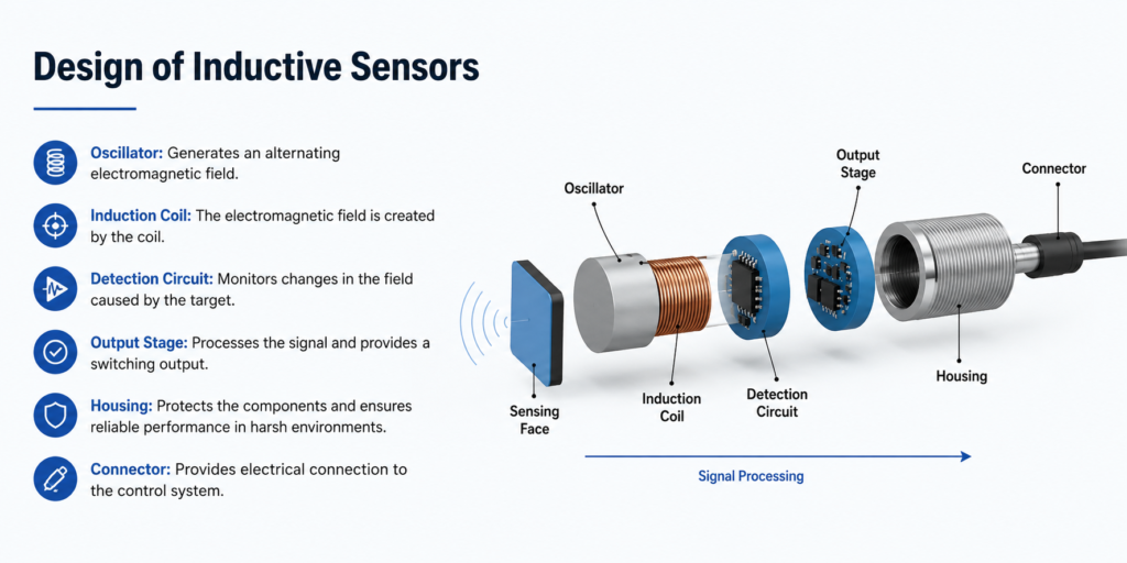
Basic Structure of an Inductive Sensor
Most inductive sensors contain several important internal parts.
The main parts are:
- Active sensing surface – the front face where the electromagnetic field is emitted
- Oscillator – generates the high-frequency signal
- Coil – creates the electromagnetic field
- Measurement field – the detection zone in front of the sensor
- Trigger stage or signal converter – detects changes caused by the metal object
- Output amplifier – sends the final signal to the PLC, relay, controller, or drive system
- Housing – protects the electronics from the industrial environment
The metallic object being detected is often called the target or attenuation object. It influences the electromagnetic field and reduces the oscillator energy.
That reduction is what the sensor electronics evaluate.
Not very dramatic. But it works beautifully in machines.
Inductive Proximity Sensors
Inductive proximity sensors are probably the most common type.
They detect whether a metal object is within the sensing distance and then change their output state. The output is usually connected to a PLC input, relay module, counter, or machine controller.
Common output types include:
- PNP normally open
- PNP normally closed
- NPN normally open
- NPN normally closed
- Two-wire DC
- AC/DC versions
- IO-Link versions
A typical example is detecting whether a metal machine part has reached its end position. When the part moves close enough to the sensor, the sensor output turns on. The PLC then knows the movement is complete and can start the next step.
That is automation in a nutshell: one signal gives permission for the next action.
Inductive Distance Sensors
Inductive distance sensors are used when a simple on/off signal is not enough.
Instead of only detecting presence, they measure how far a metal object is from the sensor. The output may be a voltage signal, current signal, or digital measurement value.
Common outputs include:
- 0–10 V
- 4–20 mA
- IO-Link
- Other digital interfaces, depending on the sensor
Inductive distance sensors are useful for applications such as:
- Position measurement
- Tool position checking
- Gap measurement
- Metal part alignment
- Vibration monitoring
- Shaft expansion monitoring
- Fine mechanical position control
They are especially useful in environments where optical sensors may struggle because of dirt, oil, coolant, metal chips, or poor surface visibility.
Inductive sensors do not care about color. They care about metal.
Inductive Sensors With IO-Link
Modern inductive sensors may include IO-Link communication.
This allows the sensor to work not only as a basic switching sensor, but also as a smart measuring and diagnostic device.
With IO-Link, the control system can receive:
- Switching status
- Measured distance value
- Adjustable switching point
- Sensor temperature
- Number of switching cycles
- Diagnostic information
- Parameter settings
This is useful for condition monitoring and maintenance planning. For example, if a sensor is getting too hot, switching too often, or operating close to its detection limit, the system may be able to detect that before a complete failure happens.
That is a nice upgrade from the old “sensor works until it doesn’t” method.
Switching Distance of Inductive Sensors
The switching distance is the distance at which an inductive sensor detects a metal object and changes its output state.
Sounds simple, but there are several different terms used when talking about switching distance. And yes, they matter.
The most important ones are:
- Nominal operating distance Sn
- Real operating distance Sr
- Usable operating distance Su
- Assured operating distance Sa
- Correction factor cf
These values help explain why a sensor may not detect every metal from the same distance.
Standard Target Plate
Inductive sensors are usually tested with a standardized metal target plate.
This plate is normally square, 1 mm thick, and made from standard steel. The side length depends on the sensor size and nominal sensing distance.
This standard target makes it possible to compare sensors under controlled conditions.
But here is the catch.
Real machine parts are not always standard test plates. They may be smaller, thinner, curved, stainless, aluminum, brass, oily, moving fast, or mounted at a strange angle. So the real switching distance on a machine can be different from the catalog value.
Catalog values are a starting point. Not a promise from the universe.
Nominal Operating Distance Sn
The nominal operating distance, shown as Sn, is the theoretical switching distance under ideal test conditions.
It is defined by the sensor manufacturer using a standard target. It does not include all real-world influences such as temperature, voltage variation, material type, installation tolerances, or target shape.
So if a sensor is listed as 8 mm Sn, that does not mean it will reliably detect every metal object at exactly 8 mm in every machine.
It means that under standard conditions, with a standard target, the nominal switching distance is 8 mm.
Important difference.
Real Operating Distance Sr
The real operating distance, Sr, is the actual switching distance of a sensor under defined conditions.
It may vary slightly from the nominal value because of manufacturing tolerances and other influences.
For many inductive proximity sensors, the real operating distance is expected to be within a certain range around the nominal distance at normal test temperature and voltage.
In practical terms, Sr is closer to what the individual sensor actually does, not just what the product family says on paper.
Usable Operating Distance Su
The usable operating distance, Su, considers additional real-world factors such as supply voltage changes, temperature changes, and mechanical tolerances.
This value is more realistic for machine operation.
A sensor may switch at a nice distance on the workbench, but the switching point can move slightly when the machine heats up, voltage drops, or the target position changes a little.
Su gives a safer idea of the range where the sensor should still operate reliably.
Assured Operating Distance Sa
The assured operating distance, Sa, is the most conservative value.
It defines the distance up to which the sensor should reliably detect the target under allowed operating conditions.
For standard inductive proximity sensors, the assured operating distance is often lower than the nominal distance. A common practical rule is that the reliable working distance is significantly less than the maximum rated distance.
This is why mounting a sensor right at the edge of its rated range is a bad idea.
Can it work? Maybe.
Will it keep working after vibration, dirt, temperature change, and machine wear? Not always.
For reliable operation, keep the target well inside the assured sensing range. Give the sensor some margin. Sensors like margin. Maintenance people like it even more.
Material Correction Factor
Inductive sensors do not detect all metals equally.
The rated sensing distance is usually based on standard steel. Other metals may reduce the sensing distance, especially non-ferrous metals like copper, brass, and aluminum.
This reduction is described by the correction factor cf.
Typical correction factors are:
| Material | Approximate Correction Factor |
|---|---|
| Steel | 1.00 |
| Copper | 0.25–0.45 |
| Brass | 0.35–0.50 |
| Aluminum | 0.30–0.45 |
| Stainless steel | 0.60–1.00 |
| Nickel | 0.65–0.75 |
| Cast iron | 0.90–1.05 |
Example:
If a sensor has a nominal sensing distance of 10 mm on steel, it may detect aluminum only at around 3–4.5 mm, depending on the sensor and the aluminum target.
That surprises people sometimes. The sensor is not broken. It is just physics being annoying.
Factor 1 Inductive Sensors
Standard inductive sensors often have reduced sensing distance on non-ferrous metals.
Factor 1 inductive sensors are designed to reduce or eliminate this material-dependent difference. They detect different metals, such as steel, stainless steel, aluminum, and brass, at roughly the same distance.
This is very useful when the machine handles different metal materials or when aluminum and stainless steel must be detected reliably.
Factor 1 sensors are especially helpful in:
- Aluminum part detection
- Stainless steel detection
- Mixed-metal production
- Tooling applications
- Packaging machines with different metal targets
- Applications where material changes often
They may cost more than standard sensors, but they can save a lot of troubleshooting time.
Switching Hysteresis
Hysteresis is the difference between the switch-on point and the switch-off point.
When a metal object approaches the sensor, the sensor switches at one distance. When the object moves away, the sensor switches back at a slightly different distance.
This difference prevents unstable switching when the target is right at the edge of the sensing range.
Without hysteresis, vibration could make the output chatter on and off quickly.
And a chattering input in a PLC program is not fun. It can cause double counts, false alarms, sequence errors, or just general chaos.
Hysteresis gives the sensor a small stable zone.
Very useful. Very underrated.
Switching Frequency
Switching frequency describes how many switching operations per second the sensor can perform.
Inductive sensors can have very high switching frequencies, often suitable for fast-moving parts and rotating machine elements.
Some inductive sensors can switch up to several kilohertz, depending on the model.
High switching frequency is useful for:
- Gear tooth detection
- Speed measurement
- Counting metal parts
- Detecting fast-moving machine components
- Monitoring rotating shafts
- Position feedback in high-speed machines
The real switching frequency depends not only on the sensor, but also on the target size, target material, mounting distance, and signal processing.
A tiny gear tooth passing too far from the sensor may not produce a clean pulse, even if the datasheet switching frequency looks impressive.
Speed Measurement With Inductive Sensors
Inductive sensors are often used to measure rotational speed.
A common method is to mount the sensor near a gear wheel, toothed wheel, metal flag, or shaft feature. Every time a metal tooth or marker passes the sensor, the output creates a pulse.
The control system counts these pulses and calculates speed.
For example:
- One pulse per revolution can measure shaft speed
- Multiple teeth per revolution give more pulses and better resolution
- A PLC high-speed counter can calculate RPM
- A frequency input can convert pulse rate to speed
This method is simple and reliable, especially in harsh environments where optical encoders may be too sensitive to dirt or oil.
Not as detailed as a full encoder, but often enough.
Resolution of Inductive Distance Sensors
For inductive distance sensors, resolution means the smallest change in distance that causes a measurable change in the output signal.
Resolution can be affected by:
- Electrical noise
- Sensor electronics
- Output type
- Measuring range
- Sampling rate
- Filtering
- Target material
- Target surface
- Installation stability
There are two useful ways to think about resolution:
- Dynamic resolution
- Static resolution
Dynamic Resolution
Dynamic resolution applies when measurements are fast.
When the target is moving quickly or the sensor is sampled at high speed, filtering is limited. The sensor must react quickly, so noise may be more visible in the signal.
This means dynamic measurement may have more signal noise and lower effective resolution than a slow measurement.
In simple words: fast measurement usually gives less time to smooth the signal.
Static Resolution
Static resolution applies when the target moves slowly or barely moves at all.
In slow applications, high-frequency noise can be filtered more effectively without affecting the useful signal. This can improve the visible resolution of the measurement.
For example, measuring slow thermal expansion of a shaft allows more filtering than measuring fast vibration.
Slow is easier to clean up. Fast is less forgiving.
Repeatability, Response Time, and Linearity
Inductive sensor performance is also described by repeatability, response time, and linearity.
These values are especially important for measuring sensors, but they also matter in switching applications.
Repeatability
Repeatability describes how accurately the sensor switches or measures the same point again and again under the same conditions.
Good repeatability is important when a machine depends on consistent positioning.
If a sensor switches at 5.0 mm once, then 5.8 mm the next time, and 4.6 mm after that, the machine may not behave consistently.
For precise automation, repeatability matters more than people sometimes think.
Response Time
Response time is how quickly the sensor output reacts to a change.
In digital sensors, it affects how fast the sensor can detect moving objects. In analog sensors, it affects how quickly the output follows distance changes.
Fast response is useful for:
- Counting parts
- Detecting gear teeth
- High-speed conveyors
- Fast machine cycles
- Motion monitoring
But response time can be affected by filtering. More filtering gives a smoother signal, but slower response.
Again, automation loves trade-offs.
Linearity
Linearity describes how closely the sensor output follows a straight-line relationship across its measuring range.
This is important for analog distance sensors.
If a sensor has poor linearity, the output may not perfectly match the real distance. The error is usually given as a percentage of full scale.
For applications that need better accuracy, there are two common options:
- Use a sensor with a linearized output curve
- Apply mathematical correction in the PLC or controller
For demanding measurement applications, checking linearity is not optional. It is part of choosing the right sensor.
Applications of Inductive Sensors
Inductive sensors are used in many industries because they are robust, compact, and reliable.
Common applications include:
- Metal part detection
- Machine position detection
- End position monitoring
- Gear tooth detection
- Shaft speed measurement
- CNC tool detection
- Tool changer confirmation
- Conveyor part counting
- Press position monitoring
- Metal object presence checking
- Assembly machine feedback
- Packaging machine position checks
- Wind turbine applications
- Harsh industrial environments
They are especially useful where dirt, oil, coolant, chips, vibration, or mechanical wear would make other sensor types less reliable.
A good inductive sensor does not care if the metal part is painted, oily, dusty, or black. If it is metal and close enough, the sensor can detect it.
Inductive Sensors in Manufacturing
In manufacturing, inductive proximity sensors are often used to monitor whether metal parts are present before the next process step starts.
For example:
- A metal part must be in position before drilling
- A stamped part must reach the next station
- A fixture must be closed
- A metal carrier must be present on a conveyor
- A machine slide must reach the correct position
These signals help prevent machine crashes, missed operations, and process errors.
One tiny sensor can protect a much more expensive machine. Not bad for something the size of a marker pen.
Inductive Sensors in CNC Machines
Inductive distance sensors and proximity sensors are widely used in CNC machines and tooling systems.
One common use is checking tool presence during automatic tool changes. The sensor can confirm whether the tool has been gripped correctly before the machine continues.
Other CNC-related uses include:
- Tool position detection
- Tool holder detection
- Metal part alignment
- Clamping confirmation
- Axis reference checks
- Fixture position monitoring
CNC environments can be harsh: coolant, chips, oil mist, vibration, and metal dust everywhere. Inductive sensors are well suited for this because they are sealed and non-contact.
Inductive vs Capacitive Sensors
Inductive and capacitive sensors are sometimes confused because both are non-contact proximity sensors.
But they are not the same.
The biggest difference is what they detect.
Inductive sensors detect metal.
Capacitive sensors can detect metal and non-metal materials, such as plastics, glass, liquids, wood, powders, and granules.
Inductive sensors use electromagnetic fields affected by metallic objects. Capacitive sensors use electrical fields affected by the dielectric properties of materials.
A simple comparison:
| Feature | Inductive Sensor | Capacitive Sensor |
| Detects metal | Yes | Yes |
| Detects plastic | No | Yes |
| Detects liquids | No, not normally | Yes |
| Detects glass | No | Yes |
| Main principle | Electromagnetic field | Electrical field / capacitance |
| Common use | Metal object detection | Level and non-metal detection |
| Sensitivity to dirt/moisture | Usually lower | Usually higher |
| Best target | Metallic objects | Liquids, plastics, powders, glass |
If the target is metal, inductive is usually the stronger and simpler choice.
If the target is non-metal, capacitive may be the better option.
Simple enough.
Advantages of Inductive Sensors
Inductive sensors have many practical advantages.
They are compact, fast, robust, and non-contact. They have no mechanical contacts to wear out. They work well in harsh environments and are less affected by dirt or color changes than optical sensors.
Main advantages include:
- Non-contact detection
- No mechanical wear
- Fast response time
- High switching frequency
- Compact design
- Good repeatability
- Reliable metal detection
- Suitable for dirty industrial areas
- Long service life
- Easy connection to PLC systems
- Good resistance to vibration and contamination
- Available in many sizes and housing types
This is why inductive sensors are one of the most common sensor types in industrial automation.
They do one job and they do it well: detecting metal.
Installation Tips for Inductive Sensors
Proper installation is important for reliable operation.
A sensor mounted badly can create false signals, missed detections, reduced sensing distance, or early failure.
Important installation points include:
- Keep the target within the assured sensing distance
- Avoid mounting at the absolute edge of range
- Use the correct flush or non-flush sensor type
- Follow free-zone requirements around the sensing face
- Tighten the sensor correctly, but do not damage the housing
- Protect cables from movement and sharp edges
- Keep sensor cables away from high-noise power cables
- Use correct PNP, NPN, two-wire, or analog wiring
- Check output type before connecting to PLC inputs
- Consider target material correction factor
- Test with the real target, not only a standard metal plate
Flush sensors can usually be mounted level with metal surfaces. Non-flush sensors often require more free space around the sensing face because their field extends wider.
If a non-flush sensor is buried in metal, its sensing field can be disturbed. It may switch incorrectly or lose range.
So yes, the mounting type matters.
Electrical Connection
Inductive sensors are available with different wiring types.
Common DC three-wire color codes are often:
- Brown = +24 V DC
- Blue = 0 V DC
- Black = output
But always check the datasheet or wiring diagram. Never assume.
Common output types include:
- PNP – switches positive voltage to the input
- NPN – switches the input to 0 V
- Normally open – output active when target is present
- Normally closed – output inactive when target is present
- Two-wire – connected in series with load/input
- Analog output – voltage or current proportional to distance
- IO-Link – digital communication and parameterization
Wrong output type is a very common reason a new sensor “does not work.”
The sensor may be fine. The PLC input just may not match it.
Classic maintenance trap.
Final Thoughts
Inductive sensors are one of the foundation pieces of industrial automation.
They detect metallic objects without contact by using an electromagnetic field. When metal enters that field, eddy currents are created in the target, the oscillator loses energy, and the sensor electronics convert that change into a switching or measuring signal.
That is the working principle.
Simple on the outside. Very useful inside.
Inductive proximity sensors are ideal for detecting metal presence and position. Inductive distance sensors are useful when the actual distance to a metal target must be measured. IO-Link versions add more flexibility by providing parameterization, digital measured values, and diagnostic data.
The key to reliable use is understanding sensing distance. Nominal distance is not the same as assured operating distance. Steel is not the same as aluminum. A standard target plate is not the same as a small real machine part. And mounting a sensor at the very edge of its range is asking for trouble later.
Used correctly, inductive sensors are fast, robust, compact, and dependable. They may not look exciting, but in real industrial machines, they are often the quiet little parts keeping everything in sequence.