A motor start button is useless if the motor stops the second you remove your finger.
That sounds obvious, but it is actually the exact problem the latch circuit solves.
In industrial automation, many machines are controlled by contactors or relays. The operator presses START, the motor runs, and it should keep running after the button is released. Then, when the operator presses STOP, the motor should stop and stay stopped.
Simple requirement.
But electrically, it needs a proper circuit.
This is where the latch principle, also called self-latching, seal-in circuit, or holding circuit, becomes one of the most important ideas in control wiring.
If you understand this one circuit properly, a lot of motor control diagrams suddenly start making sense.
What Is the Latch Principle?
The latch principle is a control circuit method that allows a relay or contactor coil to stay energized after the START button has been released.
It works by using one auxiliary normally open contact from the same relay or contactor. This contact is wired in parallel with the START button. Once the coil energizes, its own auxiliary contact closes and creates another path for current.
That path “holds” the coil energized.
In plain words:
You press START.
The contactor coil turns on.
The contactor closes its own auxiliary contact.
That auxiliary contact keeps the coil powered.
You release START.
The machine keeps running.
That is self-latching.
Small trick. Huge importance.
Why a Normal Push Button Is Not Enough

A normal push button is usually momentary.
That means it only changes contact state while you are pressing it. When you release it, a spring returns it to its normal position.
A normally open START button closes only while pressed. Once released, it opens again.
So, if you connect a motor contactor coil directly through only a normally open START button, the motor will run only while the button is held down.
That may be useful for jogging or manual movement, but it is not suitable for normal machine operation.
Nobody wants to stand there holding a button for the whole production shift. Well, hopefully not.
Basic Motor Control Problem
Imagine a machine with an electric motor.
The motor is switched by a contactor. The contactor coil is marked as C. When coil C is energized, the contactor closes its main power contacts and the motor runs. When coil C is de-energized, the contactor opens and the motor stops.
The control problem is simple:
How do we energize and de-energize contactor C from push buttons?
We need two actions:
- START should turn the motor on
- STOP should turn the motor off
But we also need memory.
After pressing START, the circuit must “remember” that the motor should continue running. After pressing STOP, the circuit must “remember” that the motor should stay stopped.
That memory is created by the latch contact.
Switch Control vs Push Button Control
One simple way to control a motor is with a maintained selector switch.
For example, a two-position switch can have:
- Position 0 = motor stopped
- Position 1 = motor running
If the switch stays in position 1, the contactor coil remains energized and the motor keeps running. If the switch is moved to position 0, the coil is de-energized and the motor stops.
This works.
But it has one major problem: after a power failure, the switch still remains in the ON position. When power returns, the motor may restart automatically.
That can be dangerous.
Push button latch control avoids this problem.
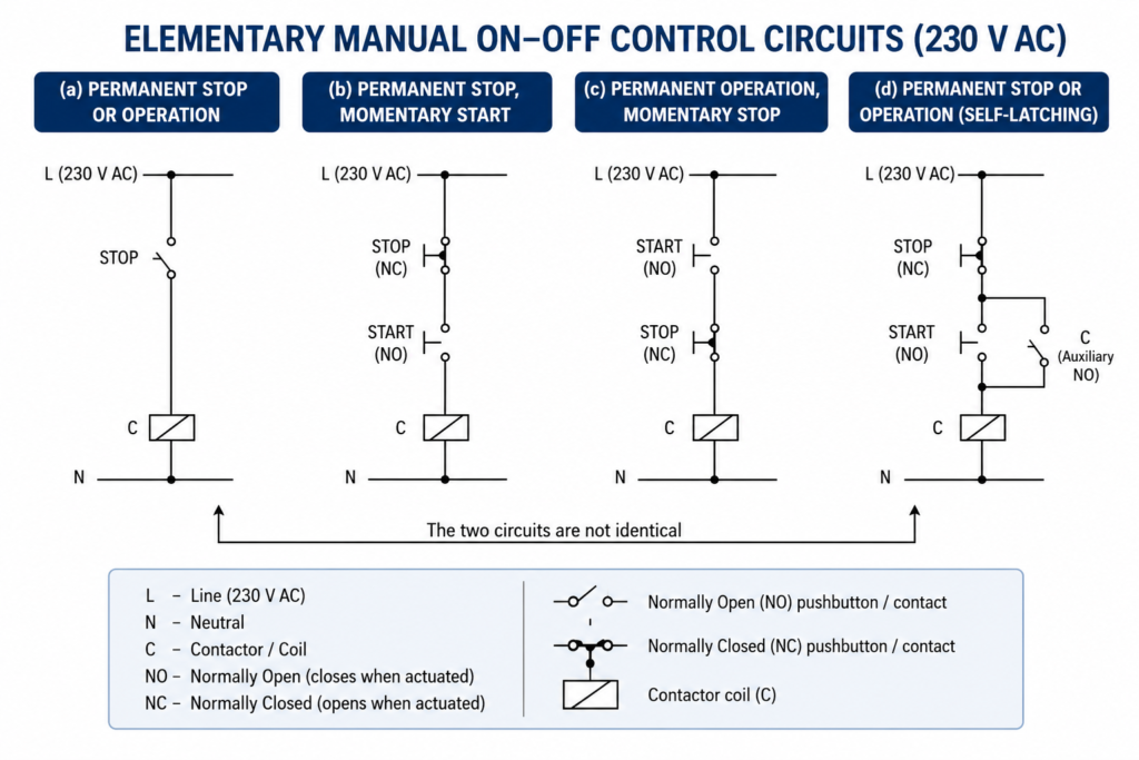
Momentary START Button Circuit
Now imagine using only a normally open START button.
When the operator presses START, current flows to the contactor coil and the motor runs.
But when the operator releases START, the button opens again, the coil loses power, and the motor stops.
So this circuit gives:
- Permanent stop
- Temporary operation while button is pressed
This is not enough for normal motor start-stop control.
It is more like a jog circuit.
Useful sometimes, but not for normal machine running.
Momentary STOP Button Circuit
The opposite arrangement is also possible.
If a normally closed push button is used in series with the coil, the motor runs normally. When the button is pressed, the contact opens and the motor stops.
But once the button is released, the contact closes again and the motor starts again.
So this gives:
- Permanent operation
- Temporary stop while button is pressed
Again, not good for normal machine control.
A STOP button should stop the machine and keep it stopped until the operator intentionally starts it again.
Otherwise, that is not really a stop button. That is just a pause button with bad manners.
The Start-Stop Latch Circuit
The proper solution is the classic start-stop latch circuit.
The circuit usually includes:
- A normally closed STOP button
- A normally open START button
- A contactor or relay coil
- A normally open auxiliary contact from the same contactor or relay
The STOP button is wired in series with the control circuit. The START button is wired in series with the coil. The auxiliary contact is wired in parallel with the START button.
This auxiliary contact is the self-latching contact.
The circuit works like this:
- The operator presses START.
- Current flows through the STOP button and START button to the contactor coil.
- The contactor coil energizes.
- The contactor auxiliary NO contact closes.
- The auxiliary contact creates a parallel path around the START button.
- The operator releases START.
- The coil remains energized through its own auxiliary contact.
- The motor continues running.
- The operator presses STOP.
- The STOP contact opens and breaks the circuit.
- The contactor coil de-energizes.
- The auxiliary contact opens.
- The motor stops and stays stopped.
That is the latch principle in action.
What Is a Self-Latching Contact?
A self-latching contact is an auxiliary contact of the same relay or contactor that it helps keep energized.
For example, contactor coil C has an auxiliary normally open contact also marked C.
When coil C is off, contact C is open.
When coil C energizes, contact C closes.
By wiring this NO contact in parallel with the START button, the contactor can feed its own coil after the START button is released.
That is why it is called self-latching.
The contactor is basically holding itself on.
Not emotionally. Electrically.
Why the STOP Button Is Normally Closed
In most start-stop circuits, the STOP button is normally closed.
That means current can flow through it during normal operation. When the operator presses STOP, the contact opens and breaks the control circuit.
This is important for safety and fault detection.
If a wire breaks in the stop circuit, the contactor coil loses power and the machine stops. If the stop button contact fails open, the machine stops. This is usually safer than using a normally open stop signal, where a broken wire might prevent the stop command from working.
In many control circuits, stop and safety-related contacts are wired normally closed for this reason.
A control circuit should fail in the safer direction where possible.
Why the START Button Is Normally Open
The START button is normally open because the machine should not start unless the operator intentionally presses it.
When START is pressed, the contact closes and energizes the coil. After the self-latching contact closes, START can be released.
This gives proper manual control:
- Press START once to run
- Press STOP once to stop
The START button does not need to carry motor current. It only controls the contactor coil circuit.
That is an important difference. The power circuit handles the motor current. The control circuit handles the command.
What Happens During a Power Failure?
One of the biggest advantages of the latch circuit is what happens after a power loss.
If the supply voltage disappears while the motor is running, the contactor coil de-energizes. When the coil drops out, its auxiliary self-latching contact opens.
Now the latch is broken.
When power returns, the motor does not automatically restart because the START button is open and the self-latching contact is also open.
The operator must press START again.
This is a very important safety feature.
Without it, machines could restart unexpectedly after a power outage. That can be dangerous for operators, maintenance staff, and the process itself.
A motor restarting by itself after power returns may cause:
- Unexpected machine movement
- Conveyor restart with people nearby
- Pumps starting under bad conditions
- Crushers or mixers starting while loaded
- Multiple machines starting at once
- Mechanical damage
- Electrical overload
- Process sequence failure
So the latch circuit does more than make a button convenient. It also prevents unwanted automatic restart after supply failure.
That matters a lot.
Why a Selector Switch Is Not the Same
A selector switch can also keep a motor running.
But it behaves differently after power loss.
If the selector switch remains in the ON position, then after power returns, the contactor coil may energize automatically. The motor starts again without anyone pressing START.
In some applications, that may be acceptable. In many machines, it is not.
The latch circuit, on the other hand, drops out during power failure and requires a new START command after power returns.
That is the key difference.
Both circuits can create permanent running while power is healthy, but only the latch circuit naturally prevents automatic restart after power loss.
Small difference on paper.
Big difference in real machines.
Example: Why Automatic Restart Can Be Dangerous
Imagine a crusher, mixer, conveyor, or cutting machine.
The machine is running. Then the power supply fails. Everything stops. An operator or maintenance person may inspect the machine, clear material, open guards, or assume the machine is safe.
If power suddenly returns and the machine starts automatically, the result can be dangerous.
Another example is a production line with several machines that must start in sequence. If all of them restart at the same instant after power returns, the process may jam, overload, or damage products.
The latch circuit prevents this by requiring an operator to restart the machine intentionally.
In automation, unexpected restart is not a small inconvenience. It is a real safety and process risk.
Control Voltage in Latch Circuits
Start-stop latch circuits can use different control voltages.
Common examples include:
- 24 V DC
- 24 V AC
- 110 V AC
- 230 V AC
In modern industrial control panels, 24 V DC is very common because it is safer for operator controls and PLC inputs. Older or simpler control circuits may use 110 V AC or 230 V AC, depending on region and machine design.
The same latch principle works with AC or DC control voltage.
Only the supply markings change.
For example:
- In a 230 V AC circuit, the supply lines may be marked phase and neutral.
- In a 24 V DC circuit, the lines may be marked +24 V and 0 V.
The logic is the same:
STOP in series.
START momentary.
Auxiliary contact in parallel with START.
Coil at the end of the branch.
Basic Wiring Logic
A simple latch circuit branch usually looks like this in logic form:
Supply → STOP NC → START NO / auxiliary NO in parallel → contactor coil → return
When the circuit is stopped:
- STOP is closed
- START is open
- Auxiliary contact is open
- Coil is off
When START is pressed:
- START closes
- Coil energizes
- Auxiliary contact closes
When START is released:
- START opens
- Auxiliary contact remains closed
- Coil stays energized
When STOP is pressed:
- STOP opens
- Coil de-energizes
- Auxiliary contact opens
After STOP is released:
- STOP closes again
- START is open
- Auxiliary contact is open
- Coil remains off
This is the memory action of the latch.
Automation Circuit Branches
Control circuits are normally drawn between two supply rails.
In many diagrams, the live or positive line is shown on one side, and the neutral or 0 V line is shown on the other. The control elements are arranged in branches between these two supply lines.
Each branch can contain different contact combinations.
A branch may include:
- Series contacts
- Parallel contacts
- Mixed series-parallel logic
- Push buttons
- Limit switches
- Relay contacts
- Timer contacts
- Safety contacts
- One relay or contactor coil
The important rule is that one branch should normally energize one coil. Contacts are used to decide when that coil receives voltage.
In practical relay logic, contacts create the conditions. The coil is the output.
Series Contacts in Control Circuits
Contacts in series act like an AND condition.
All series contacts must be closed for current to reach the coil.
For example:
STOP contact AND overload contact AND safety contact AND START command
If any one of these opens, the coil de-energizes.
This is why stop buttons, overload contacts, and safety contacts are usually wired in series with the contactor coil. Any one of them can stop the machine.
Series wiring is used when all conditions must be true.
Parallel Contacts in Control Circuits
Contacts in parallel act like an OR condition.
If any one parallel path is closed, current can pass.
In the latch circuit, the START button and auxiliary self-latching contact are in parallel.
This means the coil can be energized by either:
- Pressing the START button
- The closed auxiliary contact after the coil has energized
That is exactly how the circuit holds itself on.
Parallel wiring is used when more than one condition can activate the same output.
One Coil per Branch Rule
In traditional relay control design, a branch usually ends with one coil.
It is not good practice to place relay coils in series in the same branch. If two coils are connected in series, the voltage division and coil behavior may be unpredictable. One relay may chatter, fail to energize, or energize weakly.
Parallel coils can be used in some cases, as long as the circuit is designed correctly and the supply can handle the load.
But in clean automation diagrams, one branch usually controls one output coil.
This keeps the circuit easier to read, troubleshoot, and maintain.
And future maintenance people will silently thank you. Maybe.
Adding Overload Protection to a Latch Circuit
A real motor starter latch circuit often includes a thermal overload relay contact.
The overload relay’s normally closed auxiliary contact is wired in series with the contactor coil.
The logic becomes:
Supply → STOP NC → overload NC → START/latch contact → contactor coil → return
If the motor overloads, the overload relay trips and opens its NC contact. This breaks the coil circuit, the contactor drops out, and the motor stops.
After the overload relay is reset, the motor still does not start automatically. The operator must press START again.
That is proper behavior.
A fault should stop the machine and require intentional restart.
Adding Safety Contacts
Many machines also include safety contacts in the latch circuit.
These may come from:
- Emergency stop relay
- Guard door switch
- Safety relay
- Light curtain safety output
- Pressure switch
- Limit switch
- Safety interlock
These contacts are usually wired in series before the contactor coil.
If any safety condition opens, the contactor drops out and the latch is broken.
Again, the operator must correct the condition and press START again.
This prevents automatic restart after a safety interruption.
In modern machinery, safety circuits must follow applicable standards, so a simple latch circuit alone is not enough for safety-critical functions. But the principle is still part of many control designs.
Latch Circuit in PLC Logic
The latch principle also appears in PLC programming.
In ladder logic, a motor run command is often programmed with the same idea:
- STOP contact in series
- START contact as a momentary input
- Output contact in parallel with START
The PLC output “seals itself in” using its own status bit.
Example logic:
STOP OK → START OR MOTOR RUN → MOTOR RUN output
When START is pressed, the output turns on. Then the output’s own contact keeps the logic true. When STOP opens, the output turns off.
This is the same principle as the hardwired relay circuit.
The physical relay contact becomes a software contact.
Different technology. Same logic.
Latch vs Set/Reset Logic
In PLCs, a latch can also be created using set and reset instructions.
A START input can set a motor run bit. A STOP input can reset it.
This is useful in some programs, but it must be used carefully. Poorly written latch logic can create outputs that remain on when they should not.
The classic seal-in ladder circuit is often easier to understand for beginners because it closely matches the physical relay circuit.
For learning industrial automation, the hardwired latch circuit is still one of the best starting points.
Common Applications of Latch Circuits
The latch principle is used everywhere in automation.
Common applications include:
- Motor start-stop control
- Pump control
- Fan control
- Conveyor control
- Machine enable circuits
- Contactors
- Relay logic panels
- PLC motor control logic
- Starter circuits
- Manual machine operation
- Resettable control circuits
- Run command memory
- Process step holding
- Alarm acknowledgement circuits
Any time a momentary command must create a maintained output, a latch may be involved.
Press once, stay on.
Press stop, stay off.
That simple.
Advantages of the Latch Circuit
The start-stop latch circuit has several important advantages.
It is simple, reliable, and easy to troubleshoot. It allows momentary push buttons to control continuous operation. It prevents automatic restart after power failure. It works in both relay logic and PLC ladder logic. It can easily include stop buttons, overload contacts, safety contacts, and interlocks.
Main advantages include:
- Uses momentary push buttons
- Provides maintained operation
- Stops with one NC stop button
- Prevents automatic restart after power loss
- Easy to understand
- Easy to troubleshoot
- Works with relays, contactors, and PLC logic
- Allows additional protection contacts in series
- Very common in motor control
This is why every automation beginner should learn it early.
It is not just a “school circuit.” It is real industrial logic.
Common Mistakes
A latch circuit is simple, but people still wire it wrong.
Common mistakes include:
- Using a normally open STOP button
- Wiring the latch contact in the wrong place
- Using the wrong auxiliary contact
- Forgetting the overload NC contact
- Placing the START button in series without a holding path
- Using a contact from the wrong relay
- Connecting coils in series
- Not considering power-loss restart behavior
- Mixing control voltages
- Mislabeling contacts in the drawing
The most common beginner mistake is forgetting the self-latching contact. Without it, the motor only runs while START is pressed.
Another classic mistake is using the wrong auxiliary contact — for example, using an NC contact instead of NO. Then the circuit behaves backwards or refuses to latch.
Wiring diagrams are not decoration. They save you from these little traps.
Troubleshooting a Latch Circuit
When a latch circuit does not work, follow the voltage step by step.
If the contactor does not energize when START is pressed, check:
- Control supply voltage
- Fuse
- STOP button NC contact
- Overload relay NC contact
- Safety contacts
- START button NO contact
- Contactor coil voltage
- Neutral or 0 V return
If the contactor energizes while START is pressed but drops out when released, check:
- Auxiliary self-latching contact
- Wiring across START button
- Correct NO auxiliary contact
- Loose terminal
- Wrong contactor contact used
If the contactor will not stop, check:
- STOP button contact
- Welded auxiliary contact
- Incorrect parallel wiring
- Control circuit backfeed
- PLC output or relay contact holding the coil from another path
A good latch circuit should start, hold, stop, and stay stopped after power loss.
If it does all four, it is behaving properly.
Final Thoughts
The latch principle is one of the most important control circuit concepts in industrial automation.
It allows a momentary START button to energize a relay or contactor coil and keep it energized through its own auxiliary contact. A normally closed STOP button breaks the circuit, drops out the coil, and opens the self-latching contact.
That gives proper permanent start and stop behavior using momentary buttons.
More importantly, the latch circuit prevents unexpected automatic restart after a temporary power failure. When power is lost, the contactor drops out and the latch contact opens. When power returns, the machine stays stopped until the operator presses START again.
This is why the latch circuit is safer and more practical than a simple maintained ON/OFF selector in many motor control applications.
It is a small piece of logic, but it appears everywhere: relay panels, contactor circuits, PLC ladder programs, motor starters, conveyors, pumps, fans, and machine control systems.
Learn this circuit properly, and many automation diagrams become much less scary.
One START button. One STOP button. One auxiliary contact.
That’s where real control logic begins.