Not every machine starts because a person presses a button.
Sometimes the machine starts because a sensor says, “Now.”
That is the basic idea behind the principle of command in industrial automation. A command is the signal that allows, starts, stops, blocks, or changes the operation of a machine. It may come from a human operator using a switch or push button, but it can also come automatically from a sensor installed somewhere on the machine or process.
And that difference matters.
Manual control depends on human action. Automatic control depends on a switching signal from a device such as a photocell, limit switch, pressure switch, float switch, proximity sensor, or another field sensor.
Same control circuit idea. Different source of decision.
What Is a Command in Automation?
In automation circuits, a command is a control signal that tells a machine or relay what to do.
The command is usually created by a switching contact. When the contact changes state, the control circuit changes state too. That may energize a relay coil, start a contactor, stop a motor, trigger a timer, or send a signal to a PLC input.
In simple terms:
Contact open = command not active.
Contact closed = command active.
Of course, the exact logic depends on whether the contact is normally open or normally closed. But the principle is the same. The machine reacts to a contact state.
A command can come from:
- Selector switch
- Push button
- Limit switch
- Photocell
- Inductive sensor
- Capacitive sensor
- Pressure switch
- Float switch
- Thermostat
- Safety contact
- Relay contact
- PLC output
The control circuit does not really care whether the contact was closed by a human finger or by a sensor detecting a box on a conveyor. Electrically, it is still a command.
Manual Command
A manual command is created by a human operator.
For example, a person turns a selector switch from position 0 to position 1. The contact closes, the relay coil energizes, and the machine starts.
This is direct human control.
The operator decides when the machine runs and when it stops. The switch is usually located on a control panel, operator station, cabinet door, or nearby machine panel.
Typical manual command devices include:
- ON/OFF selector switches
- START push buttons
- STOP push buttons
- Emergency stop buttons
- Manual jog buttons
- Reset buttons
- Mode selection switches
Manual commands are simple and very common. The operator sees the machine, makes a decision, and acts.
Nothing mysterious there.
Automatic Command
An automatic command comes from a sensor or control device instead of a human operator.
For example, imagine a photocell installed on a conveyor. When there is no object in front of the sensor, its output contact is open and the machine does not run. When the photocell detects an object, the contact closes and the machine is allowed to operate.
The machine is now controlled by the sensor’s command.
No one pressed a button at that moment. The decision came from the process condition.
This is the foundation of automation: machines reacting automatically to signals from the field.
Typical automatic command sources include:
- Light sensors
- Proximity sensors
- Limit switches
- Level switches
- Pressure switches
- Temperature switches
- Flow switches
- Encoders
- Timers
- Monitoring relays
- PLC outputs
In real machines, manual and automatic commands are often combined. A machine may need the operator to press START first, but after that, sensors control the sequence.
That is where automation starts getting interesting.
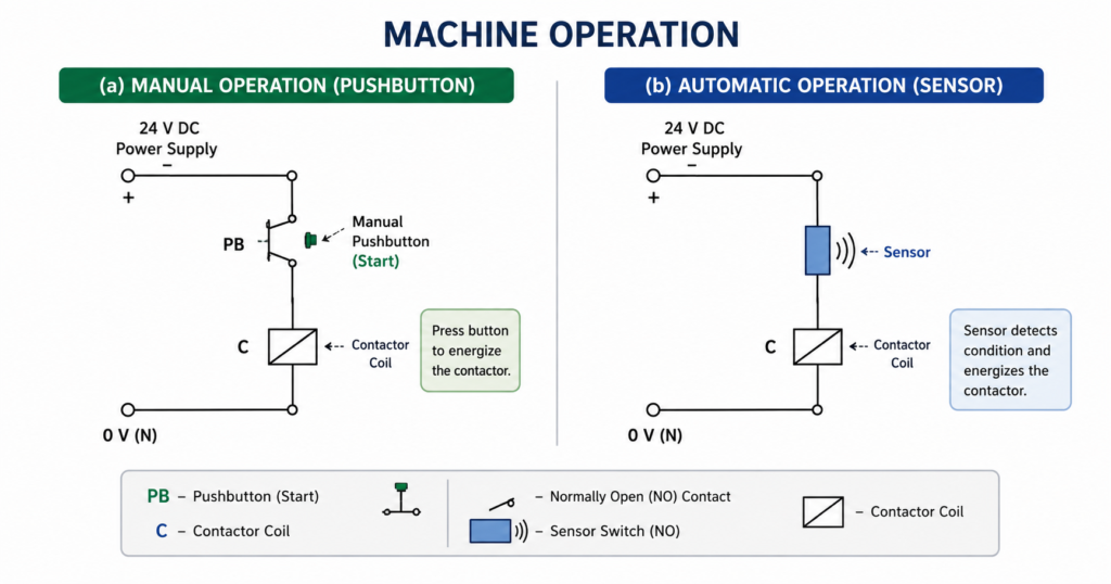
Manual vs Automatic Machine Operation
Let’s compare the two cases.
In manual operation, a selector switch or push button is used to control the relay or contactor coil. The operator physically operates the control device. The switch is usually close to the electrical cabinet or installed directly on the control panel.
In automatic operation, a sensor contact is used instead. The sensor is installed near the process where something must be detected. It may be far away from the electrical cabinet. The sensor then sends its signal back through wiring.
So the difference is not only who creates the command.
It is also where the command comes from.
Manual command: usually local and operator-controlled.
Automatic command: usually remote and process-controlled.
Small sentence. Big concept.
Example: Photocell Command
A simple example is a light sensor or photocell controlling a machine.
When no object is detected, the photocell output contact remains open. Because the contact is open, current cannot flow to the relay coil. The machine stays stopped.
When an object enters the detection area, the photocell changes its output state. The contact closes. Current can now flow through the control circuit, energizing the relay or contactor coil.
The machine starts or continues operation.
This kind of arrangement may be used for:
- Detecting products on a conveyor
- Starting a process when a part arrives
- Allowing movement only when material is present
- Counting objects
- Detecting blockage
- Triggering a machine cycle
- Starting packaging or sorting operations
The sensor becomes the command source.
The machine is not waiting for a person. It is waiting for a condition.
Command From a Distance
The word “command” in automation often also includes the idea of distance.
A manual switch is usually mounted near the automation circuit. It may be on the same electrical cabinet, on the control panel, or very close to the machine.
A sensor, on the other hand, must be installed where the physical condition exists.
A photocell must be near the conveyor.
A pressure switch must be connected to the air or hydraulic line.
A float switch must be in the tank.
A limit switch must be near the moving mechanical part.
Because of this, the command signal may travel from the field device back to the control cabinet through cables. The sensor is physically separated from the relay, contactor, PLC, or automation circuit.
That is why sensor commands are often remote commands.
The control cabinet is the brain.
The sensor is out in the machine, watching what is happening.
Two-Wire Command
When a sensor or switching device provides a simple SPST contact output, the control signal is often called a two-wire command.
SPST means single pole single throw. In normal words, it is just one contact that opens or closes one circuit path.
A two-wire command usually has two wires coming from the field contact back to the control circuit.
When the contact is open, the command is inactive.
When the contact is closed, the command is active.
This is one of the simplest command types in automation. It is commonly used with basic switches, mechanical contacts, relay outputs, and some sensors with dry-contact outputs.
Examples of two-wire command devices include:
- Limit switch contact
- Float switch contact
- Pressure switch contact
- Thermostat contact
- Relay contact
- Simple sensor contact output
Simple does not mean unimportant. A two-wire command can start a motor, stop a process, trigger an alarm, or block machine operation.
Contact-Based Control
Both manual switches and sensor commands often use the same electrical idea: contact-based control.
A contact is inserted into the control circuit. When the contact closes, the circuit is completed. When it opens, the circuit is interrupted.
This is why automation diagrams often show sensor commands as contacts instead of drawing the full internal electronics of the sensor.
For example, a photocell may contain electronics, optics, amplifier circuits, and output transistors or relay contacts. But in a simple relay control diagram, we may only show its output contact.
The internal sensor design is not always important for the control logic.
What matters is the command it provides:
Open or closed.
Active or inactive.
Signal or no signal.
How Sensor Commands Are Shown in Diagrams
In automation circuit diagrams, the exact sensor body is often not drawn completely.
Instead, the drawing shows the command point where the sensor output is used. This may be marked with a symbol or notation depending on the drawing standard, company practice, or teaching method.
The important information is usually:
- Which sensor gives the command
- Whether the contact is normally open or normally closed
- Which terminal numbers are used
- What condition activates the contact
- Which relay, PLC input, or control branch receives the signal
For example, instead of drawing the whole photocell circuit, the diagram may show a contact labeled as the photocell output.
This keeps the automation circuit readable.
Otherwise, every simple diagram would become a jungle of sensor internals, and nobody wants that.
Normally Open Command
A normally open command contact is open in its normal state.
When the device detects the required condition, the contact closes.
Example:
A photocell does not detect an object → contact open.
Photocell detects an object → contact closes.
This type is common when the machine should operate only after the condition is present.
Typical uses include:
- Start when object is present
- Allow operation when material is detected
- Count when sensor detects part
- Trigger cycle when product arrives
The logic is simple: no condition, no command.
Normally Closed Command
A normally closed command contact is closed in its normal state.
When the device detects a condition or fault, the contact opens.
Normally closed contacts are often used for stop, safety, fault, and permissive signals because an open circuit can stop the machine.
Examples include:
- Stop button
- Overload relay contact
- Safety switch
- Low pressure switch
- Guard switch
- Fault contact from monitoring relay
The advantage is that a broken wire can also interrupt the circuit. That is often safer than using a normally open contact for critical stop functions.
Of course, real safety circuits require proper safety-rated components and design, but the logic principle is still important.
Command vs Power Switching
A command signal is not usually the same as power switching.
A sensor contact may not be designed to switch a motor directly. It may only be rated for a small control current.
For example, a photocell may send a command to a relay or PLC input. The relay or PLC then controls a contactor. The contactor switches the motor power.
This separation is important.
The sensor gives the command.
The contactor switches the load.
In industrial automation, small control signals are used to control larger power devices. That is safer, more flexible, and easier to troubleshoot.
Do not ask a tiny sensor contact to do the job of a contactor. That usually ends badly.
Command in Relay Logic
In relay logic, a command contact is placed in series or parallel with other contacts to create control conditions.
For example, a motor contactor coil may energize only when several conditions are true:
- START command is active
- STOP contact is closed
- Safety contact is closed
- Overload contact is closed
- Sensor command is active
These contacts form the logic of the circuit.
A sensor command can act as:
- Start condition
- Stop condition
- Permission condition
- Interlock
- Reset signal
- Fault signal
- Sequence trigger
This is how simple contact signals become machine logic.
Command in PLC Systems
In PLC systems, sensor commands are usually wired to digital inputs.
The sensor detects something, its output changes, and the PLC input turns on or off. The PLC program then uses that input to control outputs.
For example:
- Sensor detects object
- PLC input I0.0 turns on
- PLC logic starts conveyor
- PLC output Q0.0 energizes contactor
The same command principle still applies. The only difference is that the contact signal is processed by software instead of purely hardwired relay logic.
A PLC does not remove the principle of command.
It just gives the command more logic to travel through.
Local and Remote Control
Industrial machines often have both local and remote commands.
Local commands may come from a control panel near the machine.
Remote commands may come from:
- Sensors
- PLC
- SCADA system
- Remote operator panel
- Safety system
- Process controller
- Another machine
For example, a pump may be started manually from a local panel or automatically by a level switch in a tank.
In such systems, mode selection is important. A selector switch may choose between:
- Manual mode
- Automatic mode
- Off mode
In manual mode, the operator command controls the machine.
In automatic mode, the sensor or PLC command controls the machine.
That simple mode selection prevents confusion and gives operators control when needed.
Practical Example: Tank Pump Control
A good example of command logic is a tank pump.
In manual mode, an operator presses START and STOP buttons to control the pump.
In automatic mode, a float switch or level sensor gives the command.
When the tank level rises, the level switch closes its contact. This sends a command to start the pump. When the level drops, the command disappears and the pump stops.
The pump is not being controlled by a human every time. It is being controlled by the level condition in the tank.
That is an automatic command.
And it is exactly the kind of simple automation that saves time every day.
Practical Example: Conveyor Object Detection
Another common example is conveyor control.
A photocell is mounted beside the conveyor. When a box reaches the detection point, the sensor output changes state. This command may stop the conveyor, start another conveyor, trigger a pusher, count the product, or start a packaging cycle.
The sensor command represents a real physical event:
“Box is here.”
The automation system then reacts.
This is one of the most common ideas in machine control: convert a physical condition into an electrical command.
Why the Command Principle Matters
The principle of command is important because it explains how machines make decisions.
A machine does not “know” what is happening unless it receives signals. These signals may come from people or sensors.
A command tells the machine that something should happen, may happen, or must stop happening.
Understanding this principle helps when reading automation diagrams. Instead of seeing random contacts, you start seeing decisions:
This contact allows start.
This contact blocks motion.
This sensor commands operation.
This switch selects manual control.
This fault contact stops the machine.
That is when electrical diagrams become much easier to understand.
Common Mistakes With Commands
Command circuits are simple, but mistakes happen.
Common problems include:
- Using the wrong contact type
- Mixing normally open and normally closed logic
- Wiring a sensor output directly to too large a load
- Forgetting the distance between field sensor and cabinet
- Not protecting long sensor cables
- Missing common reference voltage
- Incorrect PLC input wiring
- Wrong sensor output type
- No clear labeling in the diagram
- Confusing manual command with automatic command
A sensor may be working perfectly, but if its output contact is wired into the wrong part of the circuit, the machine will behave badly.
The command must be placed in the correct logic position.
That is the whole game.
Installation Considerations
When using sensor commands, wiring and installation matter.
Important points include:
- Use correct cable type
- Protect cables from mechanical damage
- Keep sensor wiring away from high-power motor cables
- Check voltage and contact rating
- Confirm whether the output is relay, PNP, NPN, or dry contact
- Label sensor wires clearly
- Test the command at the control cabinet
- Check the signal at the PLC input or relay coil
- Verify the real machine response
- Confirm fail-safe behavior for stop or fault commands
Because sensors are often mounted far from the control cabinet, cable faults are common. A broken wire, loose terminal, or wrong connection can make the automation circuit look wrong even when the logic is correct.
Always follow the signal from the field device back to the panel.
Final Thoughts
The principle of command is a simple but important idea in industrial automation.
A machine can be controlled manually by a human-operated switch or automatically by a sensor contact. In both cases, the operation is based on a switching signal inserted into the control circuit.
The difference is the source of the signal.
A manual command comes from a person.
An automatic command comes from a sensor, relay, controller, or process condition.
A sensor command also often includes the idea of distance, because the sensor is usually installed in the field, away from the control cabinet, where it can detect the required physical condition.
When a sensor with a simple SPST contact is used, the signal is commonly treated as a two-wire command. The contact opens or closes, and the automation circuit reacts.
This principle is everywhere: photocells on conveyors, float switches in tanks, pressure switches on air lines, limit switches on machine slides, and many more.
Automation begins when a condition becomes a command.
And once you understand that, control diagrams stop looking like random wires and start looking like machine decisions.