Industrial automation used to depend heavily on relay panels.
Lots of relays. Lots of wires. Lots of terminal blocks. Lots of time spent with a screwdriver and a wiring diagram, trying to understand why one small contact was not doing what it should.
Then PLCs arrived.
A programmable logic controller, usually called a PLC, changed the way industrial automation systems are designed, built, modified, and diagnosed. Instead of creating all control logic with physical relays, timers, counters, and hardwired contacts, a PLC allows much of that logic to be created in software.
The field devices are still real.
The motors are still real.
The sensors, buttons, valves, contactors, and lamps are still there.
But the “thinking” part of the automation system moves from hardwired relay logic into a programmable controller.
That is the heart of PLC automation.
What Is a PLC?
A PLC is a digital industrial controller used to control machines and processes.
It reads signals from input devices, executes a stored program, and then controls output devices according to that program.
In simple words:
Inputs tell the PLC what is happening.
The program tells the PLC what decisions to make.
Outputs allow the PLC to control the machine.
A PLC can process many types of automation logic, including:
- Boolean logic
- Sequential logic
- Timing functions
- Counting functions
- Mathematical operations
- Digital input and output control
- Analog signal processing
- Communication with other devices
This makes PLCs suitable for everything from small machines to large production lines.
Why PLCs Were Created
Before PLCs became common, automation systems were built mostly with electromechanical relays.
A simple control panel might contain:
- Auxiliary relays
- Timer relays
- Counters
- Contactors
- Overload relays
- Push buttons
- Switches
- Indicator lamps
- Lots of wiring between all devices
This worked, but it had problems.
Relay panels took up space. Modifications were slow. Fault finding could be painful. Every logic change required rewiring. Adding a new function often meant adding more devices and more cables.
PLCs solved many of these problems.
Instead of wiring every part of the logic physically, the logic could be programmed.
That was a big shift.
The screwdriver did not disappear, but the keyboard became just as important.
A Short History of PLCs
PLCs appeared in industry during the 1960s.
Early PLCs were much simpler than modern ones. Their main job was to replace relay logic. They acted like programmable relay systems that could perform the same basic ON/OFF logic as hardwired circuits, but with better reliability and less space.
As technology improved, PLCs became more powerful.
Important developments included:
- Digital timing functions
- Counting functions
- Synchronization features
- Microprocessor-based control
- More memory
- Better input and output modules
- Analog signal support
- Communication interfaces
- Smaller hardware
- More programming languages
Modern PLCs can be very simple or very advanced. Some are small enough for basic machine control. Others can handle large industrial processes, networks, motion control, data exchange, safety systems, and communication with computers or SCADA systems.
The basic idea stayed the same.
Read inputs. Execute logic. Control outputs.
PLC vs Personal Computer
A PLC has some similarities to a personal computer.
Both contain processing hardware, memory, and software. Both execute instructions. Both can communicate with external devices.
But their purpose is very different.
A personal computer is designed mainly for human interaction. It works with keyboards, screens, files, internet browsers, graphics, calculations, and user applications.
A PLC is designed for industrial control.
It communicates with machines, not just people.
A PLC must read sensors, buttons, switches, and other input devices. Then it must control contactors, valves, lamps, relays, drives, and other output devices. It must do this reliably in a factory environment, often for years.
That is the difference.
A PC is made to help a person work.
A PLC is made to keep a machine working.
Basic Parts of a PLC
A typical PLC system contains several main parts:
- CPU
- Memory
- Power supply
- Input modules
- Output modules
- Programming device
- Communication interfaces, depending on the PLC
Each part has a specific job.
Together, they allow the PLC to read the industrial environment, process logic, and control outputs.
CPU: The Brain of the PLC
The CPU, or central processing unit, is the brain of the PLC.
It executes the user program, processes input states, updates outputs, manages memory, and controls the internal operation of the PLC.
The CPU is responsible for:
- Reading input data
- Executing program instructions
- Processing timers and counters
- Handling internal memory bits
- Performing calculations
- Updating output states
- Managing communication
- Running diagnostics
When the PLC is in RUN mode, the CPU continuously repeats its operating cycle.
This cycle is called the PLC scan cycle.
More on that later.
PLC Memory
The PLC memory stores the program and operating data.
The user program is stored in memory so the CPU can execute it continuously. The PLC also uses memory to store input states, output states, timer values, counter values, internal relay states, and other process data.
Common memory areas include:
- User program memory
- Input image table
- Output image table
- Internal memory bits
- Timer memory
- Counter memory
- Data registers
- System memory
The memory is what allows the PLC to behave like many virtual relays, timers, and counters inside one compact controller.
In relay panels, you needed physical devices.
In PLCs, many of those devices become memory locations and software instructions.
PLC Power Supply
The PLC power supply provides the internal voltages needed by the PLC electronics.
For example, the PLC may receive 230 V AC or 24 V DC input power, but internally it may need lower voltages for the CPU, memory, and modules.
The PLC power supply feeds the internal electronics.
However, it usually does not directly supply power to large output loads such as motor contactors, solenoid valves, or actuators. Those output circuits often use external power sources.
This is important.
The PLC sends the command, but the load power must be designed correctly.
Do not expect the PLC internal power supply to do the job of a motor starter.
Input Modules
Input modules allow the PLC to receive signals from the machine or process.
Typical input devices include:
- Push buttons
- Selector switches
- Limit switches
- Proximity sensors
- Photoelectric sensors
- Pressure switches
- Float switches
- Temperature switches
- Safety contacts
- Relay contacts
- Encoder or high-speed signals, with suitable modules
- Analog sensors, with analog input modules
The input module adapts the field signal to the voltage and logic levels that the PLC electronics can understand.
For example, a sensor may provide a 24 V DC signal. The PLC input module detects that voltage and converts it into an internal logical value.
Usually:
- Input OFF = logic 0
- Input ON = logic 1
The CPU then uses that input state inside the program.
Output Modules
Output modules allow the PLC to control external devices.
Typical output devices include:
- Contactors
- Relay coils
- Solenoid valves
- Indicator lamps
- Buzzers
- Small actuators
- Motor starter control circuits
- Drive start commands
- Valve coils
- Control relays
The PLC CPU does not directly switch large industrial loads by itself. Instead, it controls output modules. The output module then provides a suitable electrical signal to the connected device.
Common PLC output types include:
- Relay outputs
- Transistor outputs
- Triac outputs
- Analog outputs
The correct output type depends on the load, voltage, current, switching speed, and application.
For example, a transistor output is good for fast 24 V DC switching. A relay output can switch different voltages but is slower and has mechanical wear.
Choosing the right output type matters.
What Does a PLC Replace?
A PLC does not replace the whole automation system.
This is important.
A PLC mainly replaces much of the hardwired control logic that used to be built with auxiliary relays, timers, counters, and complex wiring.
In a conventional relay-based automation system, you need:
- Physical auxiliary relays
- Physical timer relays
- Physical counters
- Hardwired logic connections
- Many internal panel wires
- Separate logic design and wiring work
With a PLC, much of this becomes software.
The PLC program replaces many hardwired logic connections. Internal PLC bits replace many auxiliary relay contacts. PLC timers replace many timer relays. PLC counters replace physical counters.
But the PLC does not usually replace:
- Motors
- Contactors
- Overload relays
- Sensors
- Push buttons
- Valves
- Actuators
- Lamps
- Power circuits
- Field wiring to devices
The input and output devices still exist.
The PLC simply controls them more flexibly.
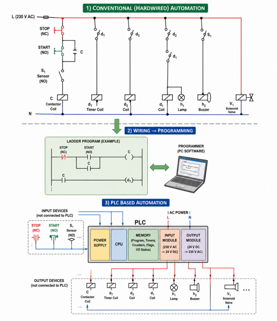
Conventional Automation vs PLC Automation
In conventional automation, the logic is created by wiring devices together.
If you want to change the logic, you often need to change the wiring.
In PLC automation, the logic is mostly created in the program.
If you want to change the logic, you may only need to modify the software.
That is a massive advantage.
For example, imagine a conveyor system. In a relay panel, adding a new condition may require extra relays, contacts, wires, terminals, and panel space. In a PLC system, you may only need to add one sensor input and modify the program.
Of course, the sensor still needs to be wired.
But the logic change is much easier.
PLC automation transforms a large part of electrical control design from fixed wiring into flexible software.
The PLC Scan Cycle
A PLC operates cyclically.
This means it repeats the same basic sequence again and again while in RUN mode.
The basic PLC scan cycle has three main steps:
- Read inputs
- Execute program
- Update outputs
Then it repeats.
Again and again.
Thousands of times while the machine is running.
This continuous cycle is called scanning.
Step 1: Reading Inputs
At the beginning of the scan cycle, the PLC reads the state of its input modules.
It checks whether each input is ON or OFF.
For example:
- START button pressed? Yes or no.
- STOP button closed? Yes or no.
- Sensor detecting object? Yes or no.
- Limit switch active? Yes or no.
- Pressure switch made? Yes or no.
The PLC stores these states in memory, often called the input image table.
The input image table is like a snapshot of all input states at that moment.
If input 3 has voltage, the PLC stores logic 1 for input 3.
If input 3 has no voltage, the PLC stores logic 0.
The program then uses this stored input information during execution.
Step 2: Executing the Program
After reading the inputs, the CPU executes the user program.
The program may contain instructions such as:
- If input 1 is active, turn on output 1
- If START is pressed and STOP is healthy, latch motor output
- If sensor detects part, increase counter
- If timer is done, open valve
- If pressure is low, stop pump
- If fault is active, turn on alarm
The CPU processes the program instruction by instruction.
It does not directly change the physical outputs immediately in every case. Instead, it calculates what the output states should be and stores those results in the output memory area.
This is usually called the output image table.
Step 3: Updating Outputs
After the whole program has been executed, the PLC updates the physical output modules.
The output image table is transferred to the output hardware.
If output 4 has been set to logic 1, the PLC turns on output 4.
If output 4 has been set to logic 0, the PLC turns off output 4.
The output module then energizes or de-energizes the connected device, such as a relay, lamp, valve, or contactor.
After the outputs are updated, the PLC begins the next scan cycle.
Read inputs.
Execute program.
Update outputs.
Repeat.
That is the basic rhythm of PLC operation.
Simple PLC Example
Imagine a very simple circuit.
A rotary switch controls a relay.
If the switch is closed, the relay should energize. If the switch is open, the relay should de-energize.
In a conventional circuit, the switch would be wired directly in series with the relay coil.
In a PLC system:
- The rotary switch is wired to a PLC input.
- The relay coil is wired to a PLC output.
- The PLC program links the input to the output.
For example:
- Input 3 = rotary switch
- Output 4 = relay C
The program logic is simple:
If input 3 is ON, turn output 4 ON.
If input 3 is OFF, turn output 4 OFF.
During the scan:
- PLC reads input 3.
- If the switch is closed, input 3 becomes logic 1.
- The program sees input 3 as true.
- The PLC writes logic 1 to output 4.
- Output 4 energizes relay C.
- The PLC repeats the scan.
This is the simplest PLC logic possible, but it explains the whole principle.
What Is Scan Time?
Scan time is the time needed for the PLC to complete one full scan cycle.
That includes reading inputs, executing the program, updating outputs, and handling internal tasks.
Scan time is usually very short, often measured in milliseconds.
However, scan time depends on:
- PLC processor speed
- Size of the program
- Type of instructions used
- Number of I/O modules
- Communication tasks
- Special functions
- Interrupts or high-speed operations
A very small program may scan extremely fast. A large program with many calculations, communication functions, and motion tasks may take longer.
Scan time matters because the PLC only detects normal input changes when it reads them.
If an input signal changes faster than the PLC can scan, the PLC may miss it.
This is why high-speed counters and interrupt inputs are used for fast signals such as encoders or very short pulses.
A PLC is fast, but it is not magic.
PLC Programming Devices
A PLC needs a programming device to create, edit, download, and monitor the program.
Today, this is usually a PC with PLC programming software installed.
Older or smaller PLC systems may also use a dedicated handheld programming device.
The programming device is mainly used during:
- Program creation
- Program downloading
- Online monitoring
- Troubleshooting
- Diagnostics
- Parameter changes
- Testing and commissioning
After the program is loaded into the PLC, the programming device is usually not needed for normal operation.
The PLC runs independently.
That is one of the important differences between programming and operation.
You use the computer to teach the PLC.
Then the PLC controls the machine by itself.
PLC Programming Languages
PLCs can be programmed using several languages.
Different manufacturers may use different software environments, different names, and different details. However, many PLC programming concepts are based on the IEC 61131-3 standard.
Common PLC programming languages include:
- Ladder Diagram
- Function Block Diagram
- Instruction List, in older systems
- Structured Text
- Sequential Function Chart
In many industrial environments, Ladder Diagram is still one of the most common languages.
Ladder Diagram
Ladder Diagram, often called ladder logic, looks similar to electrical relay diagrams.
It uses contacts, coils, branches, and rungs.
This made PLCs easier for electricians and automation engineers to understand because ladder logic looked familiar compared with relay control circuits.
For example, a start-stop motor circuit can be drawn in ladder logic almost like a hardwired control circuit.
This is one reason ladder logic became so popular in industry.
It feels like wiring, but it runs as software.
Function Block Diagram
Function Block Diagram, or FBD, represents logic using blocks.
Each block performs a function, such as AND, OR, timer, counter, comparison, or mathematical operation.
Signals flow between blocks.
FBD is useful for process control, analog signals, interlocks, and systems where visual signal flow is easier to understand than contact-based ladder rungs.
Instruction List
Instruction List, or IL, is a text-based PLC language used in many older PLC systems.
It looks more like low-level programming instructions.
For example, it may load an input, combine it with another condition, and write the result to an output.
Although it is less common in modern programming compared with Ladder, FBD, and Structured Text, it is still important to recognize because many older machines may contain IL-based programs.
Why Ladder Logic Became Popular
Ladder logic became popular because it was easy for relay-control engineers to understand.
Early PLC manufacturers needed industrial electricians and engineers to accept a new technology. If PLC programming had looked completely unfamiliar, adoption would have been much slower.
So ladder logic looked like the relay diagrams people already knew.
Contacts in series acted like AND logic.
Contacts in parallel acted like OR logic.
Coils represented outputs.
This made the jump from relay panels to PLC programming much easier.
Smart move, honestly.
Advantages of PLCs
PLCs became popular because they solve many practical automation problems.
They are compact, reliable, flexible, and easier to modify than large relay panels.
Let’s look at the main advantages.
1. Many Internal Contacts
In a relay-based system, every auxiliary contact is physical.
If a relay has only two auxiliary contacts and you need five, you must add contact blocks or additional relays.
With a PLC, this problem mostly disappears.
A PLC output, memory bit, timer done bit, or internal relay can usually be used many times in the program.
You do not run out of physical auxiliary contacts in the same way.
There are still limits based on PLC memory and software structure, but compared with relay logic, the flexibility is huge.
In PLC logic, one internal bit can be used again and again.
No extra contact block needed.
2. Time Saving
PLC systems can save a lot of engineering and installation time.
In conventional relay automation, the sequence is often:
Design the circuit.
Build the panel.
Wire the logic.
Test the control circuit.
Modify wiring if needed.
In PLC automation, programming can happen while the panel is being built and wired.
The software can be developed separately on a programming device. Then it can be downloaded to the PLC during commissioning.
This parallel work can reduce project time.
And if logic changes are needed, editing software is usually faster than rewiring half a panel.
3. Reduced Panel Space
A PLC can replace many auxiliary relays, timers, and counters.
This reduces the amount of hardware inside the control panel.
Instead of installing dozens of relay bases, timers, and wired logic paths, many functions are handled digitally inside the PLC.
This means:
- Smaller control panels
- Less wiring
- Fewer terminals
- Cleaner layout
- Easier maintenance
- Lower hardware complexity
Of course, power devices such as contactors, drives, breakers, and overloads still need space.
But the control logic hardware can be greatly reduced.
4. Easy Modification
One of the biggest advantages of a PLC is easy modification.
If you want to change the machine sequence, add a delay, change an interlock, add an alarm, or modify a condition, you can often do it in software.
In a hardwired relay system, the same change may require:
- Removing wires
- Adding relays
- Adding contacts
- Changing terminal connections
- Updating drawings
- Stopping the machine for longer
With a PLC, many changes can be made by editing the program and downloading it.
Sometimes this can be done online. Sometimes the machine must be stopped briefly. But it is usually much faster than physical rewiring.
That flexibility is one of the biggest reasons PLCs are everywhere.
5. Easier Fault Detection
PLCs are very useful for troubleshooting.
Most PLC systems allow online monitoring of the program. This means you can see which inputs are ON, which outputs are ON, which timers are active, which counters have counted, and which internal bits are true or false.
Many PLCs also have LED indicators on input and output modules.
This helps maintenance technicians quickly see:
- Is the sensor signal reaching the PLC?
- Is the start button input active?
- Is the output command turning on?
- Is the fault bit active?
- Is the timer done?
- Is the overload contact closed?
Some PLC systems also allow forcing or simulation of certain inputs and outputs for testing. This must be used carefully, but it can be very helpful during commissioning and troubleshooting.
In relay logic, you often need a multimeter and a lot of patience.
In PLC logic, online monitoring shows you the decision-making process directly.
Still need the multimeter, though. Do not throw it away.
6. Modern Engineering Environment
PLCs changed the working environment of automation engineers.
Instead of designing only with physical relays and wiring diagrams, engineers now work with programming software, simulation tools, online diagnostics, communication networks, and digital documentation.
The work became closer to computer-based engineering.
This does not mean electrical knowledge became unnecessary. Actually, good PLC work still requires strong understanding of sensors, actuators, wiring, contactors, motors, safety, and industrial processes.
But the tools became more modern.
Today, an automation engineer must understand both the panel and the program.
One without the other is not enough.
What PLCs Do Not Replace
A common beginner mistake is thinking that a PLC replaces everything.
It does not.
A PLC does not replace the power circuit.
It does not replace the motor contactor, overload protection, circuit breaker, sensors, valves, or field devices.
The PLC controls the process through inputs and outputs, but the physical machine still needs real electrical and mechanical components.
For example, if a PLC output controls a motor, it usually energizes a contactor coil or sends a command to a drive. The PLC output does not directly feed the motor.
The power circuit must still be designed correctly.
PLCs make control logic flexible.
They do not remove the need for proper electrical design.
PLCs in Modern Industry
Today, PLCs are used almost everywhere in automation.
Common applications include:
- Production lines
- Packaging machines
- Conveyor systems
- Pumping stations
- Water treatment systems
- Traffic lights
- Car washes
- HVAC systems
- Material handling systems
- Assembly machines
- CNC support systems
- Food processing lines
- Chemical processes
- Batch systems
- Machine safety control, with safety PLCs
- Robotic cells
- Industrial communication systems
From small standalone machines to large factory systems, PLCs are one of the most common automation solutions.
They are popular because they are reliable, flexible, and built for industrial environments.
Important PLC Selection Factors
Choosing a PLC is not only about buying the cheapest controller.
The engineer must study the application and select a PLC that fits the machine.
Important selection factors include:
- Number of digital inputs
- Number of digital outputs
- Analog input requirements
- Analog output requirements
- High-speed counter needs
- Communication protocols
- Memory size
- Processor speed
- Expansion module options
- Power supply voltage
- Output type
- Environmental conditions
- Programming software
- Future expansion
- Cost
- Manufacturer support
A small machine may need only a compact PLC with a few I/O points.
A larger system may need modular hardware, remote I/O, industrial Ethernet communication, analog modules, safety modules, and motion control support.
Correct PLC selection saves problems later.
Wrong selection creates limitations before the machine is even finished.
PLC Programming and Testing
After selecting the PLC, the automation logic must be programmed.
The programmer must understand:
- Machine sequence
- Input devices
- Output devices
- Safety requirements
- Start and stop behavior
- Fault handling
- Timing requirements
- Manual and automatic modes
- Alarm conditions
- Reset logic
- Communication needs
Good PLC programming is not just making outputs turn on.
It is creating predictable machine behavior.
The program should be readable, structured, documented, and easy to troubleshoot.
A messy PLC program can work today and become a nightmare next year.
PLC Installation
PLC installation includes mounting the PLC, wiring the power supply, connecting inputs and outputs, grounding correctly, and protecting the system from electrical noise.
Important installation points include:
- Correct power supply voltage
- Proper grounding
- Correct input wiring
- Correct output wiring
- Separation of signal and power cables
- Protection against electrical noise
- Correct fuse protection
- Proper terminal labeling
- Panel ventilation
- Module spacing
- Clear documentation
- Testing before operation
The PLC program may be perfect, but bad wiring can still ruin everything.
Automation is always both software and hardware.
Final Thoughts
A programmable logic controller is one of the most important devices in industrial automation.
It reads input signals from sensors, switches, and buttons. It executes a stored program. Then it controls outputs such as contactors, lamps, valves, relays, and other actuators.
Compared with conventional relay automation, PLCs reduce wiring, save panel space, simplify modifications, improve troubleshooting, and allow much more flexible machine control.
The PLC does not replace the whole industrial system. Motors, contactors, overload relays, sensors, actuators, and power circuits still remain. What the PLC replaces is much of the hardwired logic that used to require many auxiliary relays, timers, counters, and internal wiring.
The basic PLC operating cycle is simple:
Read inputs.
Execute program.
Update outputs.
Repeat continuously.
This scan cycle is the foundation of PLC operation.
Once you understand that, PLC control becomes much less mysterious. A PLC is not magic. It is a fast, reliable industrial controller making logical decisions again and again, every few milliseconds.
And in modern automation, that makes it one of the most useful tools an engineer can have.