A PLC without I/O modules is like a brain with no eyes, ears, or hands.
The CPU can execute logic. The program can be perfect. The memory can store timers, counters, bits, and instructions. But if the PLC cannot read the machine and cannot control the machine, it is not very useful.
That is where PLC I/O components come in.
I/O means input/output. PLC I/O modules are the hardware interface between the industrial field devices and the PLC processor. They allow the PLC to receive signals from sensors, buttons, switches, and instruments, then send commands to relays, valves, lamps, drives, and other output devices.
In simple words:
Inputs bring information into the PLC.
Outputs send commands out of the PLC.
That is the basic job of PLC I/O.
What Are PLC I/O Components?
PLC I/O components are the modules or built-in circuits that connect the PLC to real-world devices.
A PLC CPU works with low-power digital logic internally. But industrial devices often use higher voltages and currents, such as 24 V DC, 230 V AC, 0–10 V analog signals, 4–20 mA current loops, or other industrial signal types.
The I/O module adapts these field signals so the PLC can understand and control them safely.
For example:
A push button sends 24 V DC to a digital input.
The input module detects the voltage and tells the CPU, “This input is ON.”
The PLC program processes that information.
Then the PLC turns on a digital output.
The output module energizes a relay coil, contactor coil, lamp, or solenoid valve.
That is the full control chain.
Field device → input module → CPU program → output module → actuator.
Why PLC I/O Modules Are Important
After the CPU, I/O modules are one of the most important parts of a PLC system.
They are the connection point between software and hardware.
The PLC program may contain all the automation logic, but the actual machine still works with physical signals.
A sensor must detect something.
A button must be pressed.
A valve must open.
A motor contactor must energize.
A lamp must turn on.
The I/O modules make this possible by converting real electrical signals into internal PLC logic and converting internal PLC commands back into usable field signals.
Without I/O modules, the PLC would only be thinking to itself.
Very clever, but not very productive.
Main Types of PLC I/O Modules
The most common PLC I/O modules are:
- Digital input modules
- Digital output modules
- Analog input modules
- Analog output modules
These four types cover most industrial automation tasks.
There are also many special-purpose modules for more advanced applications, such as high-speed counters, encoder inputs, communication modules, motion control modules, temperature modules, weighing modules, and stepper motor control modules.
Depending on the PLC design, I/O can be built into the CPU or added as separate expansion modules.
Small compact PLCs often have built-in I/O.
Modular PLCs usually use separate plug-in I/O cards or modules.
Digital I/O Modules
Digital I/O modules are also called discrete I/O modules.
Both terms mean the same basic thing: ON/OFF signals.
A digital signal has only two states:
- OFF
- ON
Or in logic form:
- 0
- 1
Digital I/O is used for devices that only need a simple state, not a variable measurement.
Examples include:
- Push button pressed or not pressed
- Limit switch active or inactive
- Sensor detecting or not detecting
- Contactor coil energized or de-energized
- Lamp on or off
- Valve open command on or off
Most basic machine control depends heavily on digital I/O.
Digital Input Modules
A digital input module receives ON/OFF signals from field devices.
Typical digital input devices include:
- START push buttons
- STOP push buttons
- Selector switches
- Limit switches
- Proximity sensors
- Photoelectric sensors
- Float switches
- Pressure switches
- Relay contacts
- Overload relay contacts
- Safety relay feedback contacts
The digital input module detects whether voltage is present at each input terminal.
For a common 24 V DC input module:
- 0 V or no voltage = input OFF
- 24 V DC present = input ON
The module sends this state to the PLC CPU, usually as a logical 0 or 1.
The PLC program then uses that input state in ladder logic, function blocks, structured text, or another programming language.
Example of a Digital Input
Imagine a proximity sensor connected to PLC input I0.0.
When no metal object is detected, the sensor output is OFF. The PLC input is 0.
When a metal object comes close, the sensor output turns ON. The PLC input becomes 1.
The PLC program may then use that input to:
- Start a conveyor
- Stop a cylinder
- Count a part
- Trigger a timer
- Set an alarm
- Allow the next machine step
The sensor itself does not control the whole machine directly. It gives information to the PLC.
The PLC decides what to do with it.
Digital Output Modules
A digital output module sends ON/OFF commands from the PLC to field devices.
Typical digital output devices include:
- Relay coils
- Contactor coils
- Solenoid valves
- Indicator lamps
- Buzzers
- Small actuators
- Motor starter control circuits
- Drive start inputs
- Alarm beacons
The PLC CPU writes an output state in the program. The output module then switches the actual electrical output.
For example, if the PLC program turns output Q0.0 ON, the output module may provide 24 V DC to a solenoid valve coil.
The valve energizes.
Air flows.
A cylinder moves.
That is how a software bit becomes physical motion.
Types of Digital Outputs
PLC digital outputs can be built in different ways.
Common types include:
- Relay outputs
- Transistor outputs
- Triac outputs
Each type has different strengths.
Relay Outputs
Relay outputs use small electromechanical relays inside the PLC output module.
They can usually switch AC or DC loads, depending on rating.
Advantages:
- Can switch different voltages
- Electrically isolated output contact
- Simple to understand
- Useful for general-purpose switching
Limitations:
- Slower switching
- Mechanical wear
- Limited switching life
- Not suitable for very high-speed pulsing
- Contacts can arc or wear with inductive loads
Relay outputs are good for lamps, contactor coils, small control relays, and general machine signals.
Transistor Outputs
Transistor outputs are solid-state outputs, usually used with DC loads.
They switch faster than relay outputs and have no mechanical contacts.
Advantages:
- Fast switching
- Long life
- Good for 24 V DC loads
- Suitable for pulse outputs in some PLCs
- No mechanical wear
Limitations:
- Usually DC only
- Polarity matters
- More sensitive to overloads and short circuits
- Must match PNP/NPN or sourcing/sinking wiring style
Transistor outputs are common in modern PLCs, especially for 24 V DC automation.
Triac Outputs
Triac outputs are solid-state outputs used for AC loads.
Advantages:
- No mechanical wear
- Good for AC switching
- Faster than relay contacts
Limitations:
- AC only
- Leakage current may exist
- Not suitable for all load types
- Requires correct voltage and current rating
Triac outputs are less common in basic small-machine PLCs today but are still found in some AC control applications.
Analog I/O Modules
Digital signals are only ON or OFF.
But many industrial processes need variable values.
That is where analog I/O modules are used.
Analog signals represent a range, not just two states.
For example:
- Tank level = 63%
- Pressure = 6.8 bar
- Temperature = 82°C
- Motor speed command = 45%
- Valve opening command = 70%
Analog modules allow the PLC to read and control these continuously changing values.
Analog Input Modules
An analog input module receives variable signals from measuring instruments.
Typical analog input devices include:
- Pressure transmitters
- Level transmitters
- Temperature transmitters
- Flow meters
- Position sensors
- Load cells through converters
- Humidity sensors
- Speed feedback devices
- Current sensors
- Voltage sensors
Common analog signal types include:
- 0–10 V
- 0–5 V
- 1–5 V
- 4–20 mA
- 0–20 mA
- RTD temperature input
- Thermocouple input
The analog input module converts the electrical signal into a digital value that the CPU can use.
For example, a 4–20 mA pressure transmitter may represent 0–10 bar.
If the PLC reads 12 mA, the program can calculate that the pressure is approximately 5 bar.
The analog module does not just say ON or OFF.
It gives a measured value.
Analog Output Modules
An analog output module sends variable control signals from the PLC to external devices.
Typical analog output devices include:
- Variable frequency drives
- Control valves
- Actuator positioners
- Power controllers
- Speed controllers
- Pressure regulators
- Temperature controllers
- Dosing pumps
Common analog output signals include:
- 0–10 V
- 4–20 mA
- 0–20 mA
For example, a PLC may send a 0–10 V signal to a VFD.
- 0 V = 0% speed command
- 5 V = 50% speed command
- 10 V = 100% speed command
Or a PLC may send 4–20 mA to a control valve.
- 4 mA = valve closed
- 12 mA = valve 50% open
- 20 mA = valve fully open
Analog outputs are used when the PLC needs to control something gradually instead of simply turning it on or off.
Special PLC I/O Modules
Besides standard digital and analog modules, many PLC systems offer special-purpose modules.
Examples include:
- High-speed counter modules
- Encoder input modules
- Temperature input modules
- Thermocouple modules
- RTD modules
- Weighing modules
- Motion control modules
- Stepper motor control modules
- Servo control modules
- Communication modules
- Safety I/O modules
- Remote I/O modules
These modules are used when normal digital or analog I/O is not enough.
For example, an encoder may produce very fast pulses that a standard digital input cannot count reliably. In that case, a high-speed counter or encoder module is needed.
A thermocouple produces a very small voltage that must be measured and converted correctly. So a special thermocouple input module is used.
A stepper motor may need pulse and direction control, so a motion or pulse output module may be required.
The module must match the job.
Do not expect a standard input to do a specialist’s work.
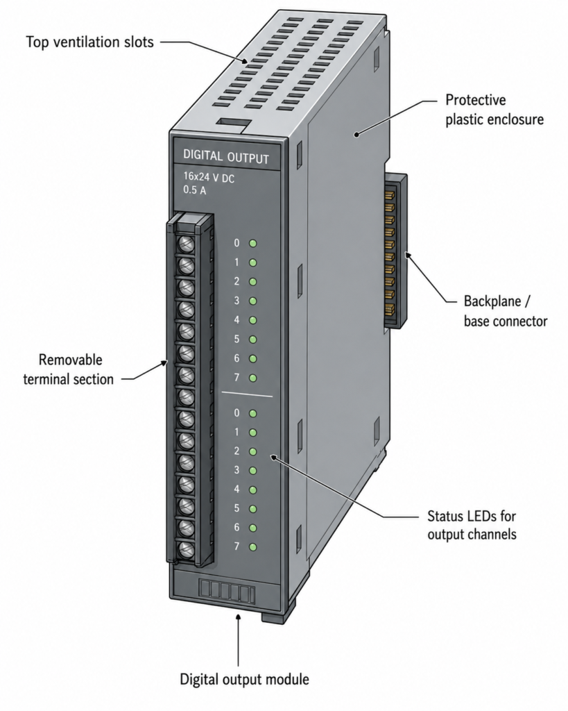
I/O Module Construction
Although PLC I/O modules look different depending on the manufacturer and PLC family, many share the same basic construction.
A typical I/O module includes:
- Plastic housing
- Electronic circuit board
- Terminal block
- Connector to the PLC backplane or base
- Status LEDs
- Mounting mechanism
- Ventilation openings
- Labeling area
The electronics inside the module handle signal conversion and communication with the CPU.
The terminal block is where field wires are connected.
The backplane or base connector allows the module to communicate with the PLC CPU and receive internal power.
The plastic housing protects the electronics and provides mechanical support.
Simple outside. Important inside.
Removable Terminal Blocks
Many PLC I/O modules use removable terminal blocks.
This is a very useful feature.
If a module fails, the terminal block with all field wiring can often be unplugged from the old module and plugged into a replacement module.
That means the technician may not need to disconnect every wire one by one.
This saves time and reduces the chance of wiring mistakes during replacement.
Removable terminal blocks are especially useful in large control panels where one module may have 8, 16, 32, or more wires connected.
Without removable terminals, replacing a module can become a slow and annoying job.
With removable terminals, it is much cleaner.
Of course, the machine must still be made safe before replacing anything.
I/O Status LEDs
Most PLC I/O modules have LED indicators.
These LEDs show the ON/OFF status of inputs or outputs.
For digital input modules, the LED usually turns on when the input receives a valid signal.
For digital output modules, the LED usually turns on when the PLC commands that output ON.
These LEDs are extremely useful during troubleshooting.
For example:
- Sensor active, but input LED off? Check wiring, voltage, sensor type, common connection.
- Input LED on, but PLC program not reacting? Check input address or program logic.
- Output LED on, but valve not energizing? Check output wiring, fuse, load power, valve coil.
- Output LED off, but valve energized? Check wiring error, backfeed, or stuck external relay.
LEDs do not replace a multimeter, but they are a fast first check.
A tiny light can save a lot of time.
Field Wiring Terminals
PLC I/O modules connect to field devices through terminals.
These terminals may be screw type, spring clamp, push-in, or removable plug style.
The conductor size depends on the module design. Many common industrial modules accept typical control wiring sizes such as 0.5 mm² to 2.5 mm², but the exact value must always be checked in the datasheet.
Good wiring practice matters.
Important points include:
- Use correct wire size
- Use ferrules where appropriate
- Tighten terminals correctly
- Label every wire
- Separate signal and power wiring
- Use shielded cable for analog signals where required
- Ground shields correctly
- Avoid loose strands
- Follow the module wiring diagram
- Check common terminals carefully
Bad wiring can make a good PLC look faulty.
It happens all the time.
PLC Module Power Supply
I/O modules often need power for two different purposes:
- Internal electronics
- Field device circuits
The PLC rack or base may provide internal power for communication and module electronics. But input sensors and output loads often require an external field power supply.
For example, a 24 V DC digital input module may need 24 V DC field voltage from an external power supply. The module detects this voltage when switches or sensors turn on.
A digital output module may also need external 24 V DC or AC supply to feed the output loads.
This means a PLC output LED can be ON, but the actual field device may still not work if the external load supply is missing.
That is an important troubleshooting point.
Always check both logic status and real field voltage.
Isolation in I/O Modules
Many I/O modules provide electrical isolation between field wiring and internal PLC electronics.
Isolation helps protect the CPU from voltage spikes, noise, wiring mistakes, and field-side disturbances.
Common isolation methods include optocouplers, transformers, relays, or isolated analog circuits.
Isolation is one reason PLCs are reliable in harsh industrial environments.
Machines are noisy.
Motors start and stop.
Contactors switch inductive loads.
Solenoids create voltage spikes.
Long cables collect interference.
The I/O module must handle all of that and still give the CPU clean information.
That is harder than it looks.
Sourcing and Sinking Inputs and Outputs
With DC digital I/O, you often hear the terms:
- Sourcing
- Sinking
- PNP
- NPN
These describe how current flows between the device and the module.
In simple practical terms:
A PNP sensor usually sends positive voltage to the PLC input when active.
An NPN sensor usually switches the input to 0 V when active.
PLC inputs and outputs must be wired to match the sensor or load type.
If the module is designed for sourcing inputs but you wire sinking sensors incorrectly, the input may never turn on.
If the output type does not match the load wiring, the device may not operate.
This is one of the most common wiring problems in PLC panels.
Always check whether the module is sourcing or sinking before wiring.
Do not guess based on wire colors alone.
I/O Addressing
Each PLC input and output has an address.
The address allows the program to refer to a specific terminal or channel.
Examples of addresses may look like:
- I0.0
- I0.1
- Q0.0
- Q0.1
- %I0.0
- %Q0.0
- X0
- Y0
The format depends on the PLC brand and programming software.
But the principle is the same.
The physical input terminal is mapped to a software address. The programmer uses that address in the PLC logic.
For example:
Input I0.0 may be a START button.
Output Q0.0 may be a motor contactor.
If the wrong address is used in the program, the real machine behavior will not match the wiring.
This is why I/O lists are so important.
I/O List and Documentation
A good PLC project should have a clear I/O list.
An I/O list usually includes:
- PLC address
- Device name
- Description
- Signal type
- Voltage or current type
- Terminal number
- Cable number
- Wire number
- Normally open or normally closed state
- Comments for troubleshooting
Example:
| Address | Device | Description | Type |
|---|---|---|---|
| I0.0 | START PB | Start push button | Digital input |
| I0.1 | STOP PB | Stop push button NC | Digital input |
| I0.2 | B1 | Product sensor | Digital input |
| Q0.0 | K1 | Motor contactor | Digital output |
| Q0.1 | H1 | Run lamp | Digital output |
Good documentation makes programming, commissioning, and troubleshooting much easier.
Poor documentation turns every fault into detective work.
And not the fun kind.
Selecting PLC I/O Modules
Choosing the correct I/O modules is a major part of PLC system design.
Important selection questions include:
- How many digital inputs are needed?
- How many digital outputs are needed?
- Are analog signals required?
- What voltage do the inputs use?
- What voltage and current do the outputs switch?
- Are outputs relay, transistor, or triac?
- Are sensors PNP or NPN?
- Are high-speed counters needed?
- Are encoders used?
- Are temperature inputs needed?
- Is remote I/O required?
- Is safety-rated I/O required?
- Is spare capacity needed for future expansion?
A common mistake is selecting exactly the number of inputs and outputs needed with no spare channels.
That may save a little money today.
Then tomorrow someone asks for one extra sensor.
Leave spare I/O where possible.
Future you will appreciate it.
Local I/O and Remote I/O
PLC I/O can be local or remote.
Local I/O is installed directly on the PLC rack, base, or expansion bus near the CPU.
Remote I/O is installed away from the PLC and communicates through an industrial network.
Remote I/O is useful when field devices are spread over a large machine or production area.
Instead of running every sensor cable back to the main PLC cabinet, a remote I/O station can be installed closer to the field devices. Then only network and power cables go back to the main control system.
This can reduce wiring cost and simplify installation.
Remote I/O is common in large machines, conveyors, process plants, and distributed automation systems.
Common PLC I/O Faults
PLC I/O problems are very common in maintenance.
Typical faults include:
- Loose terminal
- Broken wire
- Blown fuse
- Missing field supply
- Wrong common connection
- Bad sensor
- Wrong PNP/NPN wiring
- Failed output channel
- Shorted load
- Damaged relay contact
- Analog signal noise
- Incorrect scaling
- Wrong PLC address
- Module not seated properly
- Module communication fault
When troubleshooting, separate the problem into three areas:
- Field device
- Wiring and power
- PLC module and program
For example, if an input is not turning on, check the sensor first, then voltage at the input terminal, then input LED, then PLC online status, then program logic.
Do not randomly replace the PLC module first.
Most I/O faults are wiring, power, or field device issues.
Practical Troubleshooting Tips
When troubleshooting PLC I/O, use a systematic method.
For digital inputs:
- Check field device operation
- Measure voltage at the input terminal
- Check common or 0 V connection
- Check input LED
- Check PLC online input status
- Check input address in the program
For digital outputs:
- Check PLC online output command
- Check output LED
- Measure output voltage
- Check output fuse or field supply
- Check load wiring
- Measure coil or load resistance if safe
- Check for short circuits or overloads
For analog inputs:
- Check transmitter power
- Measure signal value
- Verify 4–20 mA or 0–10 V range
- Check shield grounding
- Check scaling in PLC program
- Compare field reading with HMI value
For analog outputs:
- Check PLC command value
- Measure output signal
- Confirm device input type
- Check scaling
- Verify device response
- Check cable shield and common reference
A PLC tells you what it thinks is happening.
A meter tells you what is really happening.
Use both.
Final Thoughts
PLC I/O components are the bridge between the PLC CPU and the real industrial machine.
The CPU executes the program, but the I/O modules allow the PLC to read sensors, buttons, switches, transmitters, and other input devices. They also allow the PLC to control contactors, valves, lamps, relays, drives, and other output devices.
The most common PLC I/O modules are digital input, digital output, analog input, and analog output modules. Digital modules handle ON/OFF signals. Analog modules handle variable signals such as 4–20 mA or 0–10 V.
Many PLC systems also use special modules for high-speed counting, encoder feedback, temperature measurement, weighing, motion control, safety, and communication.
A good PLC system depends on correct I/O selection, clean wiring, proper addressing, reliable power supply, good documentation, and careful troubleshooting.
The PLC program may be the brain.
But the I/O modules are how that brain sees, listens, and acts.
Ignore them, and the smartest program in the world will still fail in the field.