A PLC is not useful just because it has a CPU, memory, inputs, and outputs.
It becomes useful when it has a program.
The program tells the PLC what to do with the signals it reads from the machine. It decides when to start a motor, stop a conveyor, open a valve, turn on a lamp, count a product, trigger an alarm, or move to the next step of a sequence.
Without programming, a PLC is just hardware sitting in a control panel.
With programming, it becomes the brain of the automation system.
What Is PLC Programming?
PLC programming is the process of writing instructions that tell a programmable logic controller how to control a machine or industrial process.
The PLC reads input signals from devices such as sensors, buttons, and switches. Then it executes the user program. After that, it updates output devices such as contactors, valves, relays, lamps, and drives.
In simple words:
Inputs show what is happening.
The program decides what should happen.
Outputs make it happen.
That is the basic idea of PLC programming.
Two Parts of PLC Software
A PLC has two main software areas with different purposes.
The first part is the PLC operating system.
The second part is the user program.
These are not the same thing.
The operating system is created by the PLC manufacturer. It controls the internal operation of the PLC, such as scanning inputs, executing instructions, managing memory, communicating with modules, and updating outputs.
The user cannot normally modify the operating system.
The user program, on the other hand, is written by the automation engineer or programmer. This is where the machine logic is created.
The user program defines things like:
- Start and stop logic
- Motor control
- Sensor conditions
- Timers
- Counters
- Alarms
- Interlocks
- Sequences
- Calculations
- Analog signal processing
- Communication logic
So the operating system runs the PLC.
The user program runs the machine.
That distinction is important.
Why PLCs Need a User Program
A PLC is a digital device. It can monitor, process, and generate signals, but it does not automatically know how your machine should work.
You have to tell it.
For example, the PLC does not know that a conveyor should start only when the guard is closed, the emergency stop is healthy, the overload is reset, and the start button is pressed.
That logic must be written in the program.
A simple motor control program may say:
If STOP is healthy and START is pressed, energize motor output.
A more advanced program may say:
If product sensor detects a part, start timer.
If timer is done, extend cylinder.
If cylinder extended sensor is active, start conveyor.
If fault occurs, stop all outputs and show alarm.
This is what PLC programming is all about: turning machine requirements into executable control logic.
Early PLC Programming
Early PLCs were created mainly to replace relay control panels.
Because of that, early PLC programming was very close to relay logic.
The first PLC programs mostly used digital input and output instructions. These instructions performed basic logical functions, similar to what physical relays and contacts did in conventional automation panels.
The most common early programming language was relay ladder logic, often called ladder logic or ladder diagram.
This made sense because industrial electricians and automation engineers already understood relay circuits. PLC manufacturers needed a programming method that looked familiar.
Instead of forcing every technician to become a computer programmer overnight, ladder logic allowed them to work with contacts and coils, just like in electrical control diagrams.
Smart move.
What Is Ladder Logic?
Ladder logic is a graphical PLC programming language based on relay control circuits.
It is called “ladder” because the program looks like a ladder.
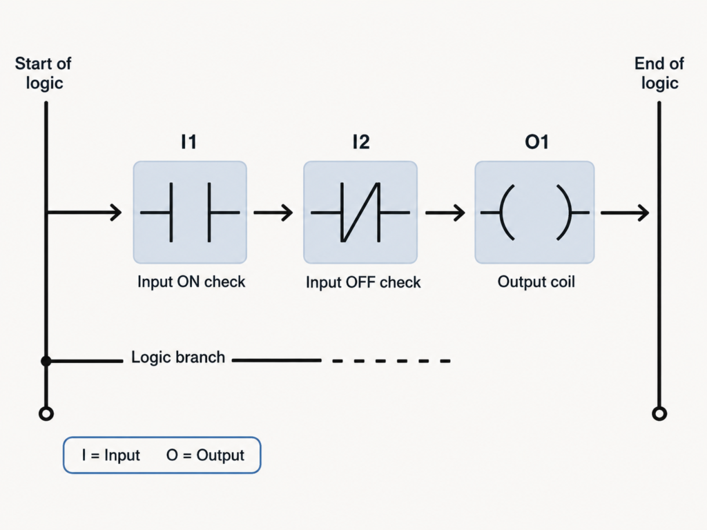
There are two vertical rails:
- The left rail represents the beginning of logic
- The right rail represents the end of logic
Between these rails are horizontal branches called rungs.
Each rung contains logical elements such as contacts, coils, timers, counters, and function blocks.
A simple ladder rung may contain:
- Input contact
- Stop contact
- Start contact
- Output coil
The PLC evaluates the rung from left to right and decides whether the output should be energized.
This is very similar to how a hardwired relay circuit works.
Ladder Logic Contacts and Coils
In ladder logic, contacts represent conditions.
Coils represent outputs or internal bits.
A contact may represent:
- Push button input
- Limit switch input
- Sensor input
- Relay status
- Internal memory bit
- Timer done bit
- Counter done bit
A coil may represent:
- PLC output
- Motor command
- Valve command
- Lamp command
- Internal relay bit
- Alarm bit
For example, a ladder rung may say:
If input I1 is ON and input I2 is OFF, energize output O1.
Graphically, this can look like an electrical circuit with contacts in series and an output coil at the end.
This is why ladder logic is still popular.
It is programming, but it feels like wiring.
Why Ladder Logic Became So Popular
Ladder logic became the most widely used PLC language because it was easy to understand for people coming from relay automation.
It has several important advantages.
First, it is graphical. You can see contacts, branches, and coils on the screen. This makes the program easier to read than pure text for many maintenance technicians.
Second, it resembles classic control circuits. Electricians who understand start-stop circuits, latching contacts, interlocks, and relay logic can usually learn ladder logic faster than text-based programming.
Third, ladder logic is good for Boolean logic. Most machine control signals are ON/OFF conditions, and ladder handles this very naturally.
Fourth, ladder logic is excellent for online troubleshooting. You can usually monitor a rung and see which contacts are true, which are false, and why an output is not turning on.
That is a huge advantage during maintenance.
PLC Programming Evolution
PLC programming did not stop with simple relay logic.
As PLC hardware became more powerful, programming languages and instructions also evolved.
Early PLCs handled mostly:
- Digital inputs
- Digital outputs
- Simple relay logic
Later, PLCs gained support for:
- Timers
- Counters
- Mathematical operations
- Comparison instructions
- Analog values
- Data registers
- Subroutines
- Communication
- Function blocks
- Motion control
- Complex process control
Modern PLCs can perform many advanced functions.
They can calculate, compare, scale analog signals, communicate with drives, exchange data with HMIs and SCADA systems, handle recipes, store production data, control motion axes, and run structured machine sequences.
That is a long way from replacing a few auxiliary relays.
Timers and Counters in PLC Programming
Timers and counters were some of the most important additions to PLC programming.
In conventional relay control, timing required physical timer relays. Counting required physical counters.
With PLCs, these functions became software instructions.
A timer can be used to:
- Delay motor start
- Delay valve closing
- Create alarm delay
- Control star-delta transition
- Create flashing signals
- Monitor process time
- Detect timeout faults
A counter can be used to:
- Count products
- Count machine cycles
- Count rejected parts
- Count start attempts
- Trigger maintenance after a number of cycles
- Track batch quantity
This reduced the need for many physical devices inside the electrical panel.
Instead of wiring a timer relay, you can create a timer in the PLC program.
Much cleaner.
Mathematical Functions in PLCs
Modern PLCs can do much more than ON/OFF logic.
They can perform mathematical operations such as:
- Addition
- Subtraction
- Multiplication
- Division
- Scaling
- Averaging
- Absolute value
- Comparisons
- Exponential functions
- Logarithmic functions
- Trigonometric functions, in advanced systems
These functions are important for analog signals and process control.
For example, a PLC may need to convert a 4–20 mA pressure signal into bar, calculate tank volume from level, compare temperature against a setpoint, or calculate motor speed from encoder pulses.
This is where PLC programming starts to become more than relay replacement.
The PLC becomes a real industrial controller.
Subroutines and Program Structure
As automation systems became larger, PLC programs needed better structure.
A small machine may only need a few ladder rungs.
A large production line may need thousands of instructions, multiple operating modes, alarm handling, recipe control, communication, diagnostics, and safety-related logic.
Writing everything in one huge program section becomes messy very quickly.
That is why modern PLC programming supports structured programming methods such as:
- Subroutines
- Functions
- Function blocks
- Program organization blocks
- Tasks
- Structured sequences
- Reusable logic blocks
This allows programmers to divide the automation system into smaller logical parts.
For example:
- Motor control block
- Valve control block
- Alarm block
- Conveyor section
- Filling sequence
- Safety feedback logic
- Communication block
- HMI data block
Good structure makes programs easier to read, test, modify, and troubleshoot.
A badly structured PLC program can still run the machine.
But it will punish everyone who has to maintain it.
Ladder Logic Is Not Always the Best Choice
Ladder logic is very useful, but it is not perfect for every application.
For simple relay-style logic, motor control, interlocks, and discrete signals, ladder is excellent.
But for large automation systems, complex sequences, mathematical processing, communication handling, or reusable control blocks, other programming languages may be better.
For example, a long step-by-step machine sequence may be easier to design with Sequential Function Chart.
A process control loop may be cleaner in Function Block Diagram.
Complex calculations may be easier in Structured Text.
This does not mean ladder logic is bad.
It means the programming language should match the problem.
Using ladder for everything is like using a screwdriver as a hammer.
Sometimes it works. Sometimes it hurts.
Common PLC Programming Languages
Modern PLC programming includes several common languages.
The most important ones are:
- Ladder Diagram
- Function Block Diagram
- Structured Text
- Sequential Function Chart
- Instruction List, mostly in older systems
These languages are commonly associated with the IEC 61131-3 standard, although each PLC manufacturer may still have its own software environment, instruction names, and implementation details.
Ladder Diagram
Ladder Diagram is the classic PLC language.
It is best for:
- Relay-style logic
- Start-stop circuits
- Motor control
- Interlocks
- Digital inputs and outputs
- Maintenance-friendly troubleshooting
- Simple machine logic
It uses contacts, coils, branches, timers, counters, and function blocks.
Many technicians prefer ladder because it is easy to monitor online and visually understand.
Function Block Diagram
Function Block Diagram, or FBD, uses graphical blocks connected together.
Each block performs a function.
For example:
- AND block
- OR block
- Timer block
- Counter block
- Comparator block
- PID control block
- Scaling block
FBD is useful when the logic is easier to understand as signal flow instead of relay contacts.
It is often used in process control, analog logic, and function-based machine control.
Structured Text
Structured Text is a text-based PLC programming language.
It looks more like traditional programming languages.
It is useful for:
- Calculations
- Loops
- Data handling
- Recipes
- Arrays
- Complex conditions
- Mathematical processing
- Communication logic
Structured Text is powerful, but it may be harder for electricians to troubleshoot if they are used only to ladder diagrams.
Still, for complex logic, it can be much cleaner than hundreds of ladder rungs.
Sequential Function Chart
Sequential Function Chart, or SFC, is used for step-based processes.
It represents automation as steps and transitions.
For example:
Step 1: Wait for part.
Step 2: Clamp part.
Step 3: Drill hole.
Step 4: Release clamp.
Step 5: Return to start.
SFC is very useful for machines that follow a clear sequence.
It makes the program easier to understand because the machine process is shown as a flow of steps.
For large sequence-based machines, SFC can be much clearer than pure ladder logic.
Instruction List
Instruction List, or IL, is a text-based low-level PLC language used in many older systems.
It uses short instructions to describe logic.
For example, it may load an input, combine it with another condition, and write the result to an output.
Instruction List is less common in modern PLC programming and has been removed or deprecated in some modern standards and platforms, but older machines may still use it.
Maintenance technicians may still meet it in old PLC programs.
So it is good to recognize it, even if you do not use it often.
IEC 61131-3 and PLC Standardization
For many years, PLC manufacturers developed their own programming languages and software tools.
This created a big problem.
Two PLC brands could both use ladder logic, but the programs were not compatible. Even two PLC families from the same manufacturer could sometimes use different notation or different instruction behavior.
This made it difficult to transfer programs between PLCs, train engineers, and standardize automation projects.
To reduce this problem, the International Electrotechnical Commission introduced the IEC 61131-3 standard.
IEC 61131-3 defines common PLC programming language concepts and structures.
It does not make every PLC brand identical, but it gives the industry a shared foundation.
This helped create more consistency in PLC programming.
Still, in real life, every manufacturer has differences.
A ladder program from one PLC software package usually cannot be copied directly into another and expected to work.
The logic may be similar.
The implementation is not always compatible.
Manufacturer Differences Still Matter
Even with standards, PLC programming is not completely universal.
Different PLC brands may use different:
- Addressing formats
- Instruction names
- Timer styles
- Counter formats
- Memory areas
- Data block structures
- Communication settings
- Programming software
- Download procedures
- Online monitoring tools
- Hardware configuration methods
For example, one PLC may use addresses like I0.0 and Q0.0. Another may use X0 and Y0. Another may use %I0.0 and %Q0.0.
The concept is the same, but the notation is different.
That is why learning PLC programming is partly about learning general principles and partly about learning the specific PLC platform.
Both matter.
Online Programming and Monitoring
One important advantage of PLC programming is online monitoring.
With the programming software connected to the PLC, the engineer can often see the program executing in real time.
This helps answer questions like:
- Is the input active?
- Is the stop circuit healthy?
- Is the timer running?
- Has the counter reached its value?
- Why is the output not turning on?
- Which interlock is blocking the sequence?
- Which alarm condition is active?
Some PLC systems also allow online edits, where small program changes can be made while the PLC is running.
This is powerful, but it must be used carefully.
Changing a live machine program without understanding the consequences can be dangerous.
Online tools are useful.
Common sense is still required.
PLC Programming and Scan Cycle
PLC programming is closely connected to the PLC scan cycle.
During operation, the PLC repeatedly performs these steps:
- Reads inputs
- Executes the program
- Updates outputs
- Repeats the cycle
The user program is executed during this scan.
This means PLC logic is evaluated again and again, usually every few milliseconds.
When a button is pressed, the PLC detects it during input reading. Then the program processes that state. Then the output is updated.
Understanding this scan cycle helps explain many PLC behaviors.
For example, very short input pulses may be missed if they are faster than the scan time, unless high-speed inputs or interrupts are used.
Also, output changes usually happen after program logic is processed, not randomly at any moment.
The scan cycle is the heartbeat of PLC programming.
From Relay Circuit to PLC Program
One of the easiest ways to understand PLC programming is to translate a simple relay circuit into ladder logic.
For example, a start-stop motor circuit contains:
- STOP button
- START button
- Motor contactor coil
- Auxiliary self-latching contact
In ladder logic, the same idea is created with:
- Normally closed STOP input contact
- Normally open START input contact
- Output coil for motor contactor
- Output contact in parallel with START for latching
The PLC program behaves like the relay circuit, but the logic is stored in software.
This is why ladder logic is so useful for learning.
It connects old relay thinking with modern programmable automation.
Basic PLC Programming Workflow
A typical PLC programming workflow includes several steps.
First, the machine operation must be understood. The programmer needs to know what the machine should do in manual mode, automatic mode, fault mode, startup, stop, reset, and emergency conditions.
Then the input and output list must be prepared.
Next, the control logic is written in the selected programming language.
After that, the program is tested, downloaded, monitored, and corrected during commissioning.
A simple workflow looks like this:
- Understand the machine process
- Prepare I/O list
- Select PLC hardware
- Create project in programming software
- Configure CPU and modules
- Assign input and output addresses
- Write logic
- Add timers, counters, alarms, and interlocks
- Test offline if possible
- Download to PLC
- Test online with real devices
- Commission safely
- Document the final program
Good PLC programming is not just writing rungs.
It is understanding the machine.
Common Beginner Mistakes in PLC Programming
Beginners often make the same mistakes.
Common PLC programming mistakes include:
- Not understanding normally open and normally closed logic
- Mixing physical contact state with PLC instruction state
- Forgetting stop and safety conditions
- Using outputs directly everywhere instead of internal bits
- Creating messy latch logic
- Not resetting faults correctly
- Using timers without considering scan behavior
- Writing logic with no comments
- Ignoring manual mode
- Ignoring fault handling
- Not documenting I/O addresses
- Making online changes without testing
- Not checking what happens after power loss
- Not considering what happens after emergency stop reset
A program can look correct when everything goes well.
The real test is what happens when something goes wrong.
Good PLC programs handle abnormal conditions clearly.
Why PLC Programming Matters
PLC programming is the link between machine requirements and machine behavior.
The wiring connects devices.
The PLC hardware processes signals.
But the program decides the logic.
A well-written PLC program makes a machine predictable, safe, easy to troubleshoot, and easy to modify.
A poorly written program can make even good hardware behave badly.
That is why PLC programming is one of the most important skills in industrial automation.
It combines electrical knowledge, logical thinking, process understanding, and practical troubleshooting.
Not just coding.
Not just wiring.
Both.
Final Thoughts
PLC programming is the process of writing the user instructions that control how a PLC responds to inputs and commands outputs.
A PLC contains manufacturer software called the operating system, which manages internal functions and cannot normally be changed by the user. The automation engineer writes the user program, which defines the logic of the machine or industrial process.
Early PLC programming was based mainly on relay ladder logic because PLCs were first created to replace relay control panels. Ladder logic became popular because it looked familiar to electricians and engineers, using contacts, coils, branches, and rungs similar to classical automation circuits.
As PLCs evolved, programming also expanded. Timers, counters, arithmetic operations, subroutines, function blocks, structured languages, and sequence-based programming became common.
Today, PLC programming may use Ladder Diagram, Function Block Diagram, Structured Text, Sequential Function Chart, or older Instruction List methods. The IEC 61131-3 standard helped create a common foundation for these languages, even though manufacturer differences still exist.
The most important point is simple:
A PLC does not control a machine by hardware alone.
It controls the machine through a program.
And the quality of that program decides how well the automation system works.