A PLC output not working can stop a machine completely.
The program says the motor should start. The HMI shows the valve should open. The output LED may even be on. But the contactor does not pull in, the lamp does not light, or the solenoid valve stays dead.
This is a very common automation fault.
The tricky part is that a PLC output problem is not always a bad PLC output. Many times, the real problem is missing field voltage, a blown fuse, a broken wire, a damaged coil, wrong output type, or a program condition blocking the output.
So do not replace the output module immediately.
Follow the signal.
What Is a PLC Output?
A PLC output is a connection point that allows the PLC to control an external device.
The PLC program decides that an output should turn ON or OFF. The output module then switches an electrical signal to a real field device.
Common PLC output devices include:
- Contactor coils
- Control relays
- Solenoid valves
- Indicator lamps
- Buzzers
- Alarm beacons
- Motor starter circuits
- Drive start inputs
- Pneumatic valve coils
- Hydraulic valve coils
- Small actuators
A PLC output is how the PLC affects the machine.
Inputs tell the PLC what is happening.
Outputs make something happen.
How a PLC Output Works
The PLC CPU executes the program and writes output states into memory.
Then the output module switches the physical output terminal.
For example:
- PLC program turns Q0.0 ON
- Output module activates output channel Q0.0
- Voltage is supplied or switched to a load
- Load energizes
The load may be a relay coil, contactor coil, solenoid valve, lamp, or signal input to another device.
The basic output chain is:
PLC program → PLC output module → output terminal → wiring → load → return/common
If one part of this chain is missing, the output device will not work.
Common Symptoms of PLC Output Problems
PLC output faults can appear in different ways.
Common symptoms include:
- Output LED is ON but device does not work
- Output LED is OFF even though the machine should run
- Output works manually but not in automatic mode
- Output turns ON in software but no voltage appears at terminal
- Output voltage appears but the load does not energize
- Output stays ON all the time
- Output flickers or chatters
- Relay output clicks but load does not work
- Transistor output gives no voltage
- Solenoid valve does not activate
- Contactor does not pull in
- Lamp is dim or flashing
- Output fuse keeps blowing
- PLC output channel is damaged
The same symptom can have several causes, so the best method is systematic testing.
Main Types of PLC Outputs
PLC digital output modules commonly use three switching technologies:
- Relay outputs
- Transistor outputs
- Triac outputs
Each type behaves differently.
Understanding the output type is important before measuring, troubleshooting, or replacing the module.
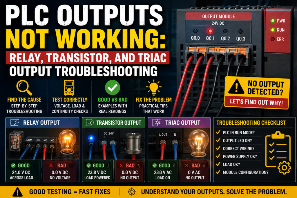
Relay PLC Outputs
A relay output uses a small electromechanical relay inside the PLC output module.
When the PLC turns the output ON, the internal relay contact closes.
Relay outputs are commonly used because they can switch different types of loads, depending on rating.
They may switch:
- 24V DC
- 230V AC
- Other AC or DC control voltages
Advantages of relay outputs:
- Simple to understand
- Can switch AC or DC loads
- Provides isolated dry contact
- Useful for general control circuits
Limitations of relay outputs:
- Mechanical wear
- Slower switching
- Limited lifetime
- Contact arcing with inductive loads
- Not suitable for very fast switching
- Contacts can weld or burn
A relay output is basically a small switch controlled by the PLC.
But like any mechanical switch, it can wear out.
Transistor PLC Outputs
A transistor output is a solid-state output used mainly for DC loads.
It switches electronically instead of mechanically.
Transistor outputs are common in 24V DC automation systems.
Advantages of transistor outputs:
- Fast switching
- No mechanical wear
- Good for DC loads
- Suitable for pulse outputs on some PLCs
- Long life when used correctly
Limitations of transistor outputs:
- Usually DC only
- Polarity matters
- Sensitive to short circuits
- Must match sourcing or sinking wiring
- Cannot switch AC loads unless designed for it
- Output current rating is limited
Transistor outputs are often used for solenoid valves, relay coils, lamps, and fast DC control signals.
But they must be protected from overloads and incorrect wiring.
Triac PLC Outputs
A triac output is a solid-state output used for AC loads.
Triac outputs switch AC voltage electronically.
Advantages of triac outputs:
- No mechanical contacts
- Suitable for AC switching
- Faster than relay contacts
- No contact wear
Limitations of triac outputs:
- AC only
- Leakage current may be present
- Not ideal for very small loads
- Can be damaged by overloads or incorrect loads
- May require minimum load current
- Not suitable for DC loads
Triac outputs are less common than relay or transistor outputs in many modern 24V DC machine panels, but they are still used in some AC control applications.
Output LED ON but Device Not Working
This is probably the most common PLC output troubleshooting situation.
The output LED is ON, but the real device does not operate.
This usually means the PLC is commanding the output, but the field circuit is not completing correctly.
Possible causes include:
- Missing field supply voltage
- Blown output fuse
- Broken wire
- Loose terminal
- Bad load coil
- Wrong common wiring
- Wrong output type
- Damaged output channel
- No neutral or 0V return
- Wrong terminal
- Interposing relay fault
- Bad connector
- Load voltage different from module voltage
The output LED only tells you the PLC is trying to switch the output.
It does not always prove that voltage is reaching the load.
You still need a multimeter.
Output LED OFF When It Should Be ON
If the output LED does not turn on, first check the PLC program.
Possible causes include:
- Output is not commanded by logic
- Safety condition is missing
- Machine is in wrong mode
- Fault bit is active
- Timer is not done
- Sensor input is missing
- Interlock is blocking output
- PLC not in RUN mode
- Output address is wrong
- Program uses different output
- Output is disabled
- Force or simulation is active
If the PLC output LED is OFF, the problem may not be electrical at all.
It may be logic.
Go online with the PLC software and follow the rung, block, or code that controls the output.
Find which condition is false.
Tools Needed for PLC Output Troubleshooting
Useful tools include:
- Multimeter
- PLC programming software
- Electrical drawing
- Small screwdriver
- Test lamp, if suitable
- Clamp meter, for larger control loads if needed
- Spare relay or fuse
- Coil resistance data, if available
- Insulated tools
- Manufacturer wiring diagram
The two most important tools are:
- Multimeter
- PLC online monitor
The PLC software shows what the program thinks.
The multimeter shows what the circuit actually has.
Both are needed.
Safety First
PLC outputs often control devices that move machines.
A solenoid valve may move a cylinder. A contactor may start a motor. A relay may energize another circuit. Testing outputs without care can cause unexpected movement.
Important safety rules:
- Follow lockout/tagout procedures
- Know what the output controls before forcing or testing it
- Keep hands clear of moving parts
- Do not bypass safety circuits
- Use proper personal protective equipment
- Be careful with 230V AC or higher control circuits
- Do not short output terminals with meter probes
- Do not disconnect wires unless the system is safe
- Use output forcing only with permission and understanding
A PLC output test should never surprise the machine operator or maintenance team.
Step 1: Identify the Output
Before measuring anything, identify the output correctly.
Check:
- PLC output address
- Device controlled by the output
- Terminal number
- Wire number
- Output module type
- Output voltage
- Load type
- Fuse or breaker
- Common terminal
- Electrical drawing
Example:
Output Q0.2 controls solenoid valve Y1.
Q0.2 is on a 24V DC transistor output module.
The valve coil is connected between output Q0.2 and 0V.
The output group common is supplied with +24V.
Now you know what to test.
Without this information, you are guessing.
Step 2: Check Online Output Status
Connect to the PLC and monitor the output online.
Check if the PLC program is actually commanding the output ON.
Possible results:
| Online Output Status | Meaning |
|---|---|
| Output is ON | PLC logic is commanding the output |
| Output is OFF | Program is not commanding the output |
| Output changes but device does not | Electrical circuit or load problem likely |
| Output never changes | Logic, mode, address, or program issue likely |
If the online output is OFF, do not start replacing output modules.
Find why the program is not turning it on.
Step 3: Check the Output LED
Most PLC output modules have status LEDs.
When the PLC commands an output ON, the LED usually turns on.
Possible results:
| Output LED | Possible Meaning |
| LED ON | PLC is commanding the channel |
| LED OFF | PLC is not commanding the channel or module issue |
| LED flickers | Output command unstable or overload/protection cycling |
| LED ON but no voltage | Missing field supply, bad output, wrong common, blown fuse |
| LED OFF but voltage present | Backfeed, wiring error, relay contact welded, external voltage |
The output LED is helpful, but it is not enough.
Always confirm voltage at the output terminal and at the load.
Step 4: Check Field Supply Voltage
Many PLC output modules need an external supply to feed the output loads.
This is especially common with transistor output modules.
For example, the PLC module electronics may be powered, and the output LED may turn on, but the load will not energize if the external 24V output supply is missing.
Check:
- Output supply fuse
- +24V supply to output common
- 0V return
- Module common terminals
- External load power
- Jumper links
- Terminal blocks
Good reading in a 24V DC output circuit:
| Measurement | Good Reading |
| +24V to 0V supply | Around 24V DC |
| Output common to 0V | Around 24V DC, if sourcing output group |
| Load return to 0V | Around 0V |
If field supply is missing, the PLC can command all day and nothing will move.
The output has no power to switch.
Step 5: Measure Voltage at the Output Terminal
When the PLC output is commanded ON, measure voltage at the output terminal.
For a common 24V DC sourcing transistor output:
| Output State | Output Terminal to 0V |
| OFF | Around 0V |
| ON | Around 24V DC |
For a relay output, voltage depends on how the contact is wired. A relay output may be a dry contact, so one side of the contact must be supplied externally.
For a triac output, measure AC voltage according to the circuit.
If the output LED is ON but there is no expected voltage at the output terminal, possible causes include:
- Missing output supply
- Blown fuse
- Wrong common wiring
- Damaged output channel
- Output module protection active
- Wiring error
- Wrong measurement reference
Step 6: Measure Voltage at the Load
Do not stop at the PLC output terminal.
Measure at the load itself.
For example, if output Q0.0 controls a 24V DC solenoid valve, measure across the valve coil terminals when the output is ON.
Good reading:
| Load Type | Expected Voltage When ON |
| 24V DC solenoid coil | Around 24V DC |
| 24V DC relay coil | Around 24V DC |
| 230V AC contactor coil | Around 230V AC |
| 230V AC lamp | Around 230V AC |
If voltage is present at the PLC output but not at the load, the problem is wiring between the PLC and load.
If voltage is present across the load but the load does not operate, suspect the load itself.
Step 7: Check the Load
A PLC output can be good while the connected load is bad.
Common load problems include:
- Burned solenoid coil
- Open relay coil
- Open contactor coil
- Wrong coil voltage
- Mechanical jam
- Valve stuck
- Lamp burned out
- Loose load terminal
- Damaged connector
- Suppression diode shorted
- Coil resistance too low
- Load current too high
For coils, you can often measure resistance with power off.
A healthy coil should not be open circuit and should not be a dead short.
Exact resistance depends on the device, voltage, and power rating.
Bad signs:
| Resistance Reading | Possible Meaning |
| OL / open circuit | Coil is broken |
| Near 0 ohms | Coil shorted |
| Much lower than expected | Damaged coil |
| Unstable reading | Bad connection or damaged coil wire |
Always isolate power before resistance testing.
Step 8: Check Output Fuse or Protection
Many PLC output circuits are protected by fuses or electronic protection.
A blown fuse is a very common reason why the PLC output LED is ON but the load does not work.
Check:
- Output group fuse
- Load fuse
- Control voltage fuse
- Electronic protection status
- Module fault LED
- Power distribution terminals
If the fuse is blown, do not just replace it and walk away.
Find out why it blew.
Possible causes:
- Shorted load coil
- Shorted cable
- Wrong wiring
- Damaged solenoid connector
- Water in connector
- Incorrect voltage
- Output overload
A fuse is not the problem.
A fuse is usually the result of the problem.
Relay Output Troubleshooting
Relay outputs are easy to understand but can fail mechanically.
Common relay output faults:
- Contact worn out
- Contact welded closed
- Contact burned
- Relay does not click
- Relay clicks but contact does not conduct
- Contact resistance too high
- Output common missing
- Wrong voltage wired through contact
Checks for relay outputs:
- Confirm PLC command online.
- Check output LED.
- Listen or feel for relay click, if safe.
- Measure voltage supply going into relay contact.
- Measure voltage leaving relay contact when ON.
- Check load voltage.
- Check load operation.
Good relay output behavior:
| Condition | Good Reading |
| Output OFF | Contact open, no voltage passed to load |
| Output ON | Contact closed, voltage passed to load |
| Contact closed resistance | Very low resistance, if isolated and safe to test |
Bad signs:
| Symptom | Possible Fault |
| LED ON, no relay click | Relay mechanism or module fault |
| Relay clicks, no output voltage | Bad contact, no supply, wiring fault |
| Output always ON | Welded contact or backfeed |
| Output intermittent | Worn contact or loose terminal |
Relay contacts wear over time, especially with inductive loads.
Transistor Output Troubleshooting
Transistor outputs are common in 24V DC PLC systems.
They are fast and reliable when wired correctly, but they can be damaged by short circuits, overloads, or wrong polarity.
Common transistor output faults:
- No voltage when ON
- Output shorted
- Output stuck ON
- Output protection active
- Wrong sourcing/sinking wiring
- Missing common supply
- Load current too high
- Inductive load without suppression
- Output damaged by reverse polarity
Checks for transistor outputs:
- Confirm output type: sourcing or sinking.
- Check field supply voltage.
- Check output common wiring.
- Command output ON.
- Measure output voltage.
- Measure voltage at load.
- Check load current and coil condition.
For a sourcing transistor output:
- Output ON usually supplies +24V to load.
- Load returns to 0V.
For a sinking transistor output:
- Load is connected to +24V.
- Output switches the load to 0V.
Do not mix these up.
Wrong polarity can make the output appear dead or damage it.
Triac Output Troubleshooting
Triac outputs are used for AC loads.
They behave differently from relay outputs.
Important things to know:
- Triacs switch AC, not DC.
- Some leakage current may exist when OFF.
- Very small loads may glow or behave strangely.
- A minimum load current may be required.
- Triacs can fail shorted or open.
Common triac output faults:
- Load does not energize
- Load stays slightly on
- Output stuck on
- Output does not switch small load correctly
- Wrong AC voltage
- DC load connected by mistake
- Module damaged by overload
Checks:
- Confirm the load is AC.
- Check supply voltage.
- Check output command.
- Measure AC voltage at output.
- Measure AC voltage across load.
- Check load current requirements.
- Check leakage-related symptoms.
A small LED lamp connected to a triac output may glow faintly because of leakage current.
That does not always mean the output is fully ON.
Good Readings for 24V DC PLC Output
For a typical 24V DC sourcing transistor output controlling a solenoid valve:
| Test Point | Output OFF | Output ON | Meaning |
| Supply +24V to 0V | ~24V DC | ~24V DC | Field supply good |
| Output terminal to 0V | ~0V | ~24V DC | Output switching good |
| Across load coil | ~0V | ~24V DC | Load receives voltage |
| Output LED | OFF | ON | PLC command visible |
| Load action | OFF | ON | Device works |
If all these are correct, the output circuit is healthy.
If the machine still does not respond, the problem may be mechanical, pneumatic, hydraulic, or process-related.
Bad Readings for 24V DC PLC Output
| Bad Reading | Possible Cause |
| No 24V field supply | Blown fuse, bad power supply, broken wire |
| Output LED ON but output terminal 0V | Missing common, damaged output, no supply |
| Output terminal 24V but load 0V | Broken wire between output and load |
| Load has 24V but does not actuate | Bad coil, stuck valve, mechanical issue |
| Output always 24V | Output shorted, transistor failed, backfeed |
| Output voltage drops low when ON | Overload, weak power supply, shorted coil |
| Fuse blows when output turns ON | Shorted load or cable |
| Output flickers | Program logic, overload protection, loose terminal, unstable supply |
Use the table as a troubleshooting shortcut.
Output Works in Manual Mode but Not Automatic
If an output works in manual mode but not automatic mode, the output hardware is probably good.
The issue is likely in the PLC logic or machine conditions.
Possible causes:
- Missing automatic mode command
- Sensor condition not satisfied
- Step sequence not active
- Timer not done
- Interlock blocking output
- Fault bit active
- Safety condition missing
- HMI command not reaching PLC
- Wrong recipe or setting
- Auto cycle not started
In this case, use online monitoring and trace the logic.
Do not troubleshoot the output module first if the output works in another mode.
Output Works When Forced but Not in Program
Forcing an output ON can help prove the field circuit works, but it must be used carefully.
If the output works when forced but not during normal program operation, then:
- Output module is likely good
- Wiring is likely good
- Load is likely good
- Program logic is not commanding it
Now troubleshoot the logic.
Check:
- Inputs
- Interlocks
- Mode selection
- Sequence step
- Fault conditions
- Timer and counter states
- Internal bits
- HMI commands
Never leave an output forced after testing.
Forcing can create dangerous machine behavior if forgotten.
Output LED ON but No Voltage at Load
This means the PLC command exists, but power is not reaching the load.
Possible causes:
- Missing field supply
- Blown fuse
- Broken output wire
- Loose terminal
- Bad output channel
- Wrong common
- Bad relay contact
- Connector fault
- Terminal jumper missing
- Incorrect wiring after maintenance
Check:
- Field supply voltage.
- Output terminal voltage.
- Voltage at each terminal between PLC and load.
- Voltage across load.
- Return path or neutral/0V.
Find where the voltage disappears.
That is where the fault is.
Output Voltage Present but Device Not Working
If correct voltage is present across the device but it does not work, suspect the device or mechanical part.
Examples:
For a solenoid valve:
- Coil burned
- Valve spool stuck
- No air pressure
- Manual override engaged
- Exhaust blocked
- Wrong voltage coil
- Connector LED faulty
For a contactor:
- Coil open
- Mechanical jam
- Wrong coil voltage
- Low voltage under load
- Auxiliary interlock issue
- Overload or safety contact open in another part of circuit
For a lamp:
- Bulb burned
- Wrong voltage lamp
- Bad lamp holder
- Polarity issue with LED lamp
Electrical voltage is only one part of the story.
The device must also be mechanically able to act.
Output Stays ON All the Time
If a PLC output stays ON when it should be OFF, possible causes include:
- PLC program is commanding it ON
- Output is forced ON
- Relay contact welded
- Transistor output shorted
- Triac output failed shorted
- Backfeed from another circuit
- Wiring short to supply
- Wrong terminal
- External relay stuck
- HMI command active
Check online status first.
If the PLC says the output is ON, find why in the logic.
If the PLC says the output is OFF but voltage is still present, suspect hardware, wiring, or backfeed.
For relay outputs, welded contacts are possible.
For transistor outputs, failed shorted outputs are possible.
For triac outputs, failed ON state is also possible.
Output Flickering or Chattering
A flickering output can be caused by logic or electrical problems.
Possible logic causes:
- Input flickering
- Sensor unstable
- Timer resetting
- Sequence step switching rapidly
- Fault condition coming and going
- Poor latch logic
- HMI command bouncing
Possible electrical causes:
- Loose terminal
- Weak power supply
- Overloaded output
- Coil drawing too much current
- Output protection cycling
- Bad module connection
- Poor common connection
Check the PLC online output status.
If the online status flickers too, the problem is in logic or input conditions.
If online status stays steady but voltage flickers, the problem is electrical.
Wrong Output Type
Using the wrong output type can cause failure.
Examples:
- DC load connected to triac AC output
- AC load connected to DC transistor output
- Load current too high for transistor output
- Fast pulse application using relay output
- Inductive load without suppression
- Sinking output wired as sourcing
- Sourcing output wired as sinking
Always check:
- Output voltage rating
- Output current rating
- AC or DC compatibility
- Load type
- Switching frequency
- Common wiring
- Protection requirements
A PLC output is not just “an output.”
The type matters.
Interposing Relays
Sometimes PLC outputs do not drive loads directly. Instead, they energize interposing relays.
An interposing relay is used between the PLC and the field device.
Reasons include:
- Higher load current
- Different voltage
- Electrical isolation
- Protecting PLC output
- Multiplying contacts
- Easier maintenance
If the output controls an interposing relay, troubleshoot in two stages:
- PLC output to interposing relay coil
- Interposing relay contact to field load
Possible problems:
- PLC output works but relay coil is bad
- Relay energizes but contact is bad
- Wrong relay contact used
- Relay base loose
- Contact burned
- Wrong voltage relay coil
- Missing supply on relay contact side
Interposing relays add flexibility, but they also add another possible fault point.
Suppression for Inductive Loads
Many PLC outputs control inductive loads, such as relay coils, contactor coils, and solenoid valves.
When an inductive load turns off, it can create a voltage spike.
This spike can damage transistor outputs, relay contacts, or other electronics.
Suppression devices help control this.
Common suppression methods include:
- Flyback diode for DC coils
- RC snubber for AC circuits
- Varistor
- Surge suppressor module
- Built-in coil suppression
If outputs keep failing, check whether inductive loads have proper suppression.
One missing diode can kill outputs repeatedly.
PLC Output Module Faults
PLC output modules can fail, but confirm the basics first.
Before replacing a module, check:
- PLC command status
- Output LED
- Field supply
- Output fuse
- Common wiring
- Load condition
- Wiring to load
- Output rating
- Module diagnostics
- Shorts or overloads
Signs of a possible bad output channel:
- PLC command ON
- Output LED ON
- Field supply present
- Common correct
- Load disconnected
- No output voltage
- Other outputs on same module work
- Moving load to spare output works
If a module or channel is damaged, find the cause before replacing it.
Otherwise, the new module may fail too.
Troubleshooting Flow for PLC Outputs
Use this simple flow:
- Identify output address and device.
- Check electrical drawing.
- Monitor output online in PLC software.
- Check output LED.
- Check field supply voltage.
- Check output common.
- Measure voltage at output terminal.
- Measure voltage at load.
- Check load coil or device.
- Check fuse and protection.
- Check wiring between PLC and load.
- Check for forces, faults, and interlocks.
- Confirm output type and rating.
This method saves time and avoids unnecessary part replacement.
Real Example: Output LED ON, Solenoid Dead
Problem:
PLC output Q0.4 LED is ON, but solenoid valve Y2 does not energize.
Checks:
- Online output Q0.4 = TRUE
- Output LED ON
- Output terminal to 0V = 24V DC
- Across solenoid coil = 0V
Likely fault:
Broken wire or loose terminal between PLC output and solenoid coil.
Fix:
Trace the wire through terminal blocks and connectors. Repair loose or broken connection.
Real Example: Output ON, Contactor Not Pulling In
Problem:
PLC output commands motor contactor K1, but contactor does not pull in.
Checks:
- PLC output LED ON
- 230V AC present at one side of contactor coil circuit
- 0V across contactor coil
- Overload NC contact open in series with coil
Likely fault:
Thermal overload relay tripped or overload auxiliary contact open.
Fix:
Investigate overload cause, reset if safe, and test again.
The PLC output was fine. The series control circuit blocked the contactor.
Real Example: Output Fuse Blows
Problem:
Output fuse blows every time the solenoid valve output turns ON.
Checks:
- Output wiring correct
- Solenoid connector wet
- Coil resistance very low
Likely fault:
Shorted solenoid coil or water-damaged connector.
Fix:
Replace coil or connector, dry and protect wiring, then replace fuse.
Do not install a bigger fuse.
That is not troubleshooting. That is asking for smoke.
Best Practices to Prevent PLC Output Problems
Good design and maintenance prevent many output faults.
Best practices include:
- Use correct output type for the load
- Check load current before wiring
- Use interposing relays for larger loads
- Use proper fusing
- Add suppression for inductive loads
- Label all wires
- Keep drawings updated
- Leave spare outputs
- Separate control and power wiring
- Use correct terminal tightening
- Protect cables from movement and damage
- Check common wiring carefully
- Document all output addresses
- Avoid overloading PLC outputs
A PLC output module is not a power distribution block.
Respect its ratings.
Final Thoughts
When a PLC output is not working, the problem can be in the program, output module, field supply, common wiring, fuse, cable, terminal, load, or mechanical device.
The best troubleshooting method is to follow the output signal step by step.
First, check whether the PLC program is commanding the output. Then check the output LED. After that, measure field supply voltage, output terminal voltage, and voltage directly across the load.
For relay outputs, check the contact and supply path. For transistor outputs, check DC polarity, sourcing or sinking wiring, output common, and load current. For triac outputs, check AC voltage, leakage current, load type, and minimum load requirements.
If the output LED is ON but the device does not work, do not assume the PLC is bad.
Check the field voltage.
Check the fuse.
Check the load.
Check the common.
Check the wire.
A PLC output only works when the complete circuit works.
Follow the voltage, follow the logic, and the fault becomes much easier to find.