A machine stopping in the middle of production always has that same lovely timing.
Never during a quiet test run. Never when everyone is relaxed. Usually it happens when the operator is waiting, the supervisor is looking over your shoulder, and the line has already started collecting half-finished parts like some kind of industrial traffic jam.
And then someone says the classic sentence:
“The PLC is faulty.”
Maybe. But honestly? Most of the time, it isn’t.
A PLC can fail, sure, but before blaming the controller, there are several boring little things that should be checked first. Power, emergency stops, sensors, interlocks, air pressure, safety relays, output devices, loose wires, tripped breakers. The usual suspects. Not glamorous, but they cause a ridiculous amount of downtime.
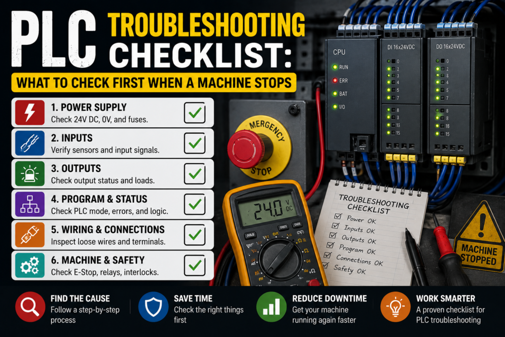
This checklist is written for real troubleshooting on real machines, not perfect textbook conditions. The goal is simple: when a machine stops, what should you check first so you don’t waste one hour chasing ghosts inside the PLC program?
First: Do Not Start Randomly Resetting Everything
I know. The reset button is tempting.
Press reset, cycle power, try again, hope the fault disappears. Sometimes it works. Sometimes it also clears the only clue you had.
Before touching anything, take a few seconds and look around.
Ask yourself:
- What exactly stopped?
- Did the whole machine stop, or only one section?
- Is there an alarm on the HMI?
- Did it stop during startup, automatic cycle, or while moving?
- Did someone open a guard door?
- Was there a product jam?
- Is there air pressure?
- Are any lights flashing on the control panel?
Small details matter. A machine that stops during homing is not the same problem as a machine that stops after 10 minutes of normal running. Different smell, different animal.
And yes, sometimes the operator already knows the answer but doesn’t know it’s important. Ask what happened just before the stop. “It just stopped” often becomes “it stopped after I changed the product size” or “it stopped after I opened this door.” Big difference.
1. Check the Obvious Safety Conditions First
When a machine suddenly refuses to run, safety circuits are one of the first things to check.
Not because they are always faulty, but because they are designed to stop the machine immediately. That is literally their job.
Check these first:
- Emergency stop buttons
- Safety gate switches
- Light curtains
- Safety mats
- Safety relays
- Door locks
- Guard switches
- Two-hand control units
- Safety PLC status, if the machine uses one
Look at the safety relay or safety controller. Most safety relays have LED indicators that show whether the input channels are healthy and whether the output is enabled.
A very common situation: one emergency stop button is slightly pressed, or a door is not fully closed. Not open enough to look obvious, but enough to break the safety input. Annoying little thing.
If the machine has a safety PLC, check the diagnostic screen or safety fault messages. Many modern systems will tell you exactly which gate, zone, or safety input is blocking operation.
Important: never bypass safety devices just to “test quickly.” That quick test can turn into a very bad day. Use the proper diagnostic method, follow lockout/tagout rules, and keep hands out of moving areas.
2. Look at the HMI Alarm Screen
This should be near the top of the checklist, but in real life people often skip it.
The HMI is not just decoration. It usually gives the first useful clue.
Check:
- Active alarms
- Alarm history
- Machine status screen
- Step number or sequence state
- Interlock page
- Manual mode diagnostics
- I/O status screen, if available
A good HMI might show something like:
- “Low air pressure”
- “Safety circuit not reset”
- “Cylinder forward sensor not detected”
- “Servo drive fault”
- “Motor overload tripped”
- “Product not detected”
- “Home position missing”
That is already half the troubleshooting done.
But be careful. Some alarms describe the result, not the real cause. For example, “Cylinder not extended” does not always mean the cylinder is bad. It could be no air, a faulty solenoid valve, a blocked mechanical part, or a sensor that failed to detect the position.
The alarm points you in the direction. It doesn’t always hand you the answer wrapped in a ribbon.
3. Check Main Power and Control Voltage
If the machine looks completely dead, start with power.
Simple, boring, necessary.
Check the incoming supply first. Then move deeper into the control panel.
Common checks:
- Main isolator on
- Main breaker not tripped
- Fuses healthy
- 24V DC power supply working
- Control transformer output correct
- PLC power LED on
- HMI powered
- Safety relay powered
- Input and output modules powered
For most PLC control systems, the 24V DC supply is critical. Sensors, input modules, relays, contactors, solenoid valves, and safety devices often depend on that 24V line.
A weak or overloaded 24V power supply can create strange faults. The machine might start, then stop. Sensors may flicker. Outputs may drop. The PLC might stay alive while field devices behave like they had too much coffee.
Use a multimeter and measure the voltage. Do not only look at the power supply LED. A green LED is nice, but it doesn’t prove the voltage is correct under load.
Typical good reading:
- Around 24V DC, often between 23V and 25V depending on the system
Bad signs:
- 0V DC
- Very low voltage
- Voltage dropping when outputs turn on
- Power supply cycling on and off
- Burnt smell or visible damage
- Tripped protection on the DC circuit
If there are multiple 24V power supplies, check the correct one. Machines love having several supplies and making you chase the wrong circuit for 20 minutes.
4. Check the PLC Status LEDs
The PLC itself usually tells you a lot before you even connect a laptop.
Look at the status LEDs.
Common indicators include:
- Power
- Run
- Stop
- Error
- Fault
- Battery
- Communication
- I/O fault
- Module status
If the PLC is in RUN mode, that is good news. The program is executing. The problem may still be in the logic or field devices, but at least the PLC is alive.
If the PLC is in STOP mode, the machine will not run normally. Then you need to find out why.
Possible causes:
- Program error
- Hardware fault
- Missing module
- Memory issue
- CPU switched to STOP manually
- Power interruption
- Communication problem
- Serious diagnostic fault
For Siemens PLCs, for example, you may see RUN/STOP, ERROR, MAINT, and communication LEDs depending on the model. Allen-Bradley, Omron, Mitsubishi, Schneider, and others have their own LED names, but the idea is similar.
Don’t guess from the LEDs alone. Check the PLC manual or diagnostic software if needed.
A red fault light does not automatically mean the PLC is broken. It means the PLC detected something wrong.
That “something” might be a disconnected remote I/O module at the far end of the machine. Been there. Lovely.
5. Check Emergency Stop and Reset Logic
Many machines will not restart after an emergency stop until the reset sequence is done correctly.
Usually the machine needs:
- All safety devices healthy
- Emergency stop released
- Safety relay reset
- Machine reset button pressed
- No active faults
- Start command given
If one condition is missing, nothing happens.
This is where people often say, “The start button doesn’t work.”
Maybe the start button is fine. The machine is just not ready to accept start.
Look for a “ready” signal. On the HMI, this may be shown as:
- Machine ready
- Safety OK
- Auto ready
- Drive ready
- Air pressure OK
- Home complete
- No active alarm
If there is no clear HMI diagnostic page, use the electrical drawing and PLC input status to check the reset chain.
6. Check Air Pressure and Pneumatic Supply
On machines with pneumatic cylinders, low air pressure can stop everything.
Many PLC programs include an air pressure switch as an interlock. If pressure drops below the allowed level, the machine stops or refuses to start.
Check:
- Main air supply valve
- Regulator setting
- Pressure gauge
- Filter/regulator unit
- Air pressure switch
- Leaks
- Dump valve
- Soft-start valve
- Solenoid valve supply
Good reading depends on the machine, but many industrial pneumatic systems work around 5–6 bar. Do not assume this value; check the machine requirement.
Bad signs:
- Gauge at 0 bar
- Pressure too low
- Pressure drops when cylinder moves
- Air leaking loudly
- Regulator closed
- Manual valve shut
- Pressure switch not changing state
A funny one: after maintenance, someone closes the air valve and forgets to open it. The PLC gets blamed. The poor PLC had nothing to do with it.
7. Check Sensors and PLC Inputs
Sensors are one of the most common reasons a machine stops mid-cycle.
A PLC makes decisions based on input signals. If a sensor does not give the expected signal, the program may wait forever.
Typical sensors include:
- Inductive proximity sensors
- Photoelectric sensors
- Capacitive sensors
- Limit switches
- Reed switches on cylinders
- Pressure switches
- Level sensors
- Encoder signals
- Temperature switches
Check the PLC input LED and the sensor LED at the same time if possible.
Example:
A cylinder is extended physically, but the PLC input for “cylinder extended” is off. That means the PLC does not know the cylinder reached position.
Possible reasons:
- Sensor is misaligned
- Sensor cable damaged
- Sensor has no 24V supply
- Wrong sensing distance
- Broken sensor
- Input module fault
- Loose terminal
- Mechanical part not reaching the sensor
- Magnet missing inside pneumatic cylinder piston
For a 3-wire DC sensor, you normally check:
- Brown wire: +24V DC
- Blue wire: 0V DC
- Black wire: signal output
Again, always check the actual wiring diagram. Most sensors follow this color code, but “most” is not the same as “all.” Machines enjoy exceptions.
Good sign:
- Sensor LED changes when the target is present
- PLC input LED changes at the same time
- Voltage at input changes properly
Bad sign:
- Sensor LED changes, but PLC input does not
- PLC input stays permanently ON
- PLC input stays permanently OFF
- Voltage is weak or floating
- Sensor flickers randomly
When the sensor LED works but the PLC input does not, suspect wiring, terminal, input card, or wrong input common.
When neither the sensor LED nor PLC input works, check sensor power, alignment, or the sensor itself.
8. Check Outputs: Relays, Contactors, Solenoids, and Valves
PLC outputs command things to happen.
But an output LED turning on does not guarantee the device actually moved. This is a trap.
For example, the PLC output LED may turn on for a solenoid valve. But the cylinder still doesn’t move.
Why?
Maybe the solenoid coil is burned. Maybe there is no air. Maybe the valve is stuck. Maybe the output relay contact is bad. Maybe the wire is broken. Maybe the cylinder is jammed. Plenty of fun options.
Check outputs in layers:
- Is the PLC output command ON?
- Is the output LED ON?
- Is voltage present at the output terminal?
- Is voltage present at the device coil?
- Does the device react?
- Does the feedback sensor confirm movement?
For relay outputs, remember that the PLC output contact may switch an external voltage. You need to check the common supply feeding that output group.
For transistor outputs, check whether the output is PNP or NPN. Wrong assumptions here can make readings look confusing.
For contactors, check:
- Coil voltage
- Overload relay status
- Auxiliary contact feedback
- Mechanical movement
- Burnt or worn contacts
- Control fuse
For solenoid valves, check:
- Coil voltage
- Manual override
- Valve stuck
- Air supply
- Exhaust blockage
- Coil resistance
- Connector LED, if present
A good output test is not just “the PLC says ON.” A good output test follows the signal all the way to the device.
9. Check Motor Overloads, Drives, and Servo Faults
Motors are another usual troublemaker.
If a conveyor, pump, fan, or actuator stops, check its protection and drive system.
For direct-on-line motors, check:
- Motor protection breaker
- Thermal overload relay
- Contactor
- Fuses
- Auxiliary feedback
- Motor terminals
- Mechanical jam
For VFD-controlled motors, check:
- VFD display
- Fault code
- Drive ready signal
- Enable signal
- Start command
- Speed reference
- Motor cable
- Overcurrent or overload faults
- DC bus fault
- Communication status
For servo systems, check:
- Servo drive alarm
- Encoder cable
- Motor power cable
- Enable signal
- Home sensor
- Limit switches
- Following error
- Mechanical blockage
- Brake release
Do not just reset a drive fault five times and hope for a miracle. Read the fault code. It usually tells you whether the issue is overload, overcurrent, undervoltage, encoder fault, overheating, or communication loss.
Also, mechanical problems can create electrical alarms. A jammed conveyor may trip an overload. A stuck axis may cause servo following error. A blocked pump may overload a motor. The electrical cabinet is not always the crime scene.
Sometimes the crime scene is a bent bracket.
10. Check Communication Between PLC, HMI, Drives, and Remote I/O
Modern machines depend heavily on communication.
Profinet, Profibus, EtherNet/IP, Modbus TCP, Modbus RTU, EtherCAT, CANopen — whatever the system uses, a lost communication link can stop the machine instantly.
Check:
- Ethernet cables
- Industrial switches
- Remote I/O modules
- Drive communication status
- HMI connection
- PLC communication LEDs
- Device IP addresses
- Network connectors
- Damaged cables
- Loose RJ45 plugs
- Termination resistors on bus systems
A communication fault can look scary, but sometimes it is painfully simple. Someone opened the panel, moved a cable, and now one RJ45 connector is not fully clicked in.
For remote I/O, look at module LEDs. If a whole group of sensors and valves suddenly disappears from diagnostics, the problem may be the remote I/O station, not each individual device.
Do not replace five sensors when one remote I/O module has lost power. That is how troubleshooting turns expensive.
11. Check the Machine Sequence Step
This is where PLC troubleshooting becomes more interesting.
Many automatic machines run in steps. Step 10 waits for a part. Step 20 clamps it. Step 30 moves a cylinder. Step 40 checks a sensor. Step 50 starts a motor. You get the idea.
When the machine stops, find out which step it is stuck in.
A good HMI may show:
- Current step number
- Waiting condition
- Active interlock
- Missing sensor
- Timeout alarm
If the HMI does not show it, you may need to connect with PLC software and monitor the logic.
When you know the stuck step, ask:
- What output should be active in this step?
- What input is the PLC waiting for?
- Is there a timer running?
- Has a condition changed?
- Is an interlock blocking the next step?
Example:
The machine is stuck waiting for “part present.” The sensor is off. You check the sensor and find it is covered in dust. Clean it, signal returns, machine continues.
No PLC replacement. No drama. Just dirt.
Very industrial, really.
12. Use Manual Mode Carefully
Manual mode is useful because you can test individual outputs and movements.
But use it carefully.
Before jogging anything, make sure:
- Nobody is inside the machine
- Guards and safety rules are respected
- The movement direction is understood
- Mechanical area is clear
- Air and power are safe
- You know what the button will actually do
Manual mode can help you test:
- Cylinders
- Motors
- Clamps
- Solenoid valves
- Indexing units
- Conveyors
- Vacuum ejectors
- Grippers
If a device works in manual mode but not in automatic mode, the hardware may be fine and the problem is likely a missing condition in the automatic sequence.
If it does not work in manual mode either, then check output, wiring, actuator, supply, and mechanical parts.
That is a very useful split. Manual mode separates logic problems from hardware problems — not perfectly, but enough to point you somewhere.
13. Check Mechanical Problems Before Blaming Electrical Parts
This one hurts because electrical people often stay inside the panel too long.
A machine can stop because something mechanical is wrong.
Check:
- Jammed product
- Bent brackets
- Loose sensor mounts
- Worn belts
- Broken chains
- Stuck bearings
- Misaligned guides
- Cylinder rod damage
- Gripper not closing fully
- Part not seated correctly
- Dirt, dust, oil, or metal chips
A sensor may be “faulty” only because the metal target is 5 mm too far away.
A motor may trip because the conveyor is jammed.
A cylinder may not extend because the mechanism is physically blocked.
So yes, open the panel. But also look at the machine itself. The answer is sometimes outside the cabinet, sitting there like a villain in plain sight.
14. Check Wiring and Terminals
Loose wires cause beautiful nightmares.
Intermittent faults, random stops, flickering inputs, outputs that work only sometimes. The kind of fault that disappears when you arrive and returns during night shift, because of course it does.
Check:
- Loose terminals
- Broken wires
- Damaged cables
- Cable glands
- M12 connectors
- Sensor plugs
- Relay sockets
- Ground connections
- Common wires
- Terminal jumpers
- Cabinet vibration areas
Pull gently on suspicious wires. Do not yank like you’re starting a lawnmower, but check if anything is loose.
Look for:
- Burn marks
- Discoloration
- Broken insulation
- Crushed cables
- Oil-filled connectors
- Corrosion
- Moisture
- Poor cable routing near moving parts
For intermittent faults, wiggle testing can help, but do it safely and carefully. Also, don’t ignore vibration. Machines vibrate all day, every day. Terminals that were tight two years ago may not be tight now.
15. Use the Electrical Drawings
Trying to troubleshoot without drawings is possible.
It is also a great way to waste time.
Use the electrical schematic to follow the signal properly:
- From sensor to terminal
- From terminal to PLC input
- From PLC output to relay
- From relay to coil
- From power supply to output common
- From safety relay to enable circuit
Good drawings save hours.
Bad drawings still save some time, usually.
Check wire numbers, terminal numbers, PLC addresses, fuse references, relay contacts, and device tags. If the machine has been modified over the years, drawings may not be fully correct, so verify with actual wiring.
Trust the drawing, but not blindly. A healthy amount of suspicion is useful in maintenance work.
16. Connect to the PLC Only After Basic Checks
Connecting a laptop to the PLC is powerful, but it should not be the first move every time.
Before going online with PLC software, check:
- Safety status
- HMI alarms
- Power supply
- PLC status LEDs
- Air pressure
- Obvious tripped breakers
- Sensor LEDs
- Drive faults
After that, PLC monitoring becomes very useful.
You can check:
- Input status
- Output status
- Fault bits
- Step sequence
- Timers
- Counters
- Interlock conditions
- Communication diagnostics
- Drive command signals
- Alarm logic
But do not change the program unless you are absolutely sure. Troubleshooting is not the same as editing. A quick “temporary change” can create a bigger problem than the original fault.
If you must modify logic, make a backup first. Always.
Quick PLC Troubleshooting Checklist
Here is the simple version you can keep near the machine.
When a machine stops, check in this order:
- Look at the machine
- Product jam?
- Mechanical blockage?
- Operator opened something?
- Any obvious damage?
- Check the HMI
- Active alarms
- Alarm history
- Step number
- Missing condition
- Check safety
- Emergency stops
- Guard doors
- Light curtains
- Safety relay or safety PLC
- Reset required?
- Check power
- Main breaker
- Control voltage
- 24V DC supply
- Fuses
- PLC power
- Check PLC status
- RUN/STOP
- Error LEDs
- I/O faults
- Communication faults
- Check air pressure
- Regulator
- Pressure switch
- Air valve
- Leaks
- Dump valve
- Check sensors
- Sensor LED
- PLC input LED
- Alignment
- Cable
- Target position
- Check outputs
- PLC output LED
- Output voltage
- Relay or contactor
- Solenoid coil
- Actuator movement
- Check drives and motors
- VFD fault code
- Servo alarm
- Overload relay
- Motor protection
- Mechanical jam
- Check communication
- Remote I/O
- Ethernet cables
- Network switches
- Drive communication
- HMI connection
- Use manual mode
- Test movement safely
- Confirm actuator works
- Separate hardware fault from logic fault
- Go online with PLC software
- Monitor inputs and outputs
- Check sequence step
- Check interlocks
- Check timers and fault bits
Good vs Bad Signs During PLC Troubleshooting
| Area | Good Sign | Bad Sign |
|---|---|---|
| PLC CPU | RUN light on, no fault LEDs | STOP mode, red fault light, no power |
| 24V DC supply | Stable around 24V DC | 0V, low voltage, voltage drops under load |
| Safety circuit | Safety relay reset and outputs active | E-stop active, guard open, safety relay not enabled |
| Sensor | Sensor LED and PLC input change together | Sensor LED changes but PLC input does not |
| Output | PLC output turns on and device receives voltage | Output ON in PLC but no voltage at device |
| Pneumatics | Correct pressure and stable movement | Low pressure, leaks, stuck valve |
| Motor drive | Drive ready, no active fault | Fault code, overload, no enable signal |
| Communication | Devices online and healthy | Remote I/O lost, network fault, drive offline |
| Mechanical system | Free movement, no jam | Bent parts, blocked actuator, jammed product |
Common Mistakes When Troubleshooting PLC Machines
The biggest mistake is assuming too early.
People see a stopped machine and immediately decide: “Bad PLC output.” Then they spend an hour testing the output card, only to find that the emergency stop circuit was not reset.
Another common mistake is ignoring feedback sensors. A cylinder may move, but if the PLC does not receive the end-position signal, the machine still thinks the movement failed.
Also, don’t trust only one indication. A sensor LED is useful. A PLC input LED is useful. A voltage measurement is better. Together, they tell the story.
And please, please, do not replace parts randomly. Replacing parts without testing is not troubleshooting. That is gambling with company money.
Sometimes it works, which is the dangerous part, because then people keep doing it.
Simple Example: Machine Stops During Automatic Cycle
Let’s say a machine stops while moving a pneumatic cylinder forward.
The HMI says:
“Cylinder forward timeout.”
What should you check?
First, check if the cylinder physically moved.
If it did move forward, check the forward position sensor. Maybe the sensor is misaligned or not switching. Check the sensor LED, then check the PLC input.
If the cylinder did not move, check whether the PLC output for the solenoid valve is ON. If the output is ON, measure voltage at the valve coil. If voltage is present, check the coil, valve, air supply, and mechanical blockage. If voltage is not present, check wiring, output module, fuse, relay, or output common.
If the PLC output is not ON, then the program may be blocked by another condition. Check interlocks, safety, air pressure, automatic step, and alarms.
That is how you narrow it down. Not by magic. Just by following the chain.
Command → output → device → movement → feedback.
That chain solves a lot of PLC troubleshooting problems.
Final Thoughts
When a machine stops, the PLC is only one part of the story.
A PLC reads inputs, runs logic, and switches outputs. It depends on sensors, power supplies, safety circuits, drives, relays, valves, wiring, and mechanical parts. If one piece of that chain fails, the whole machine can stop.
So the best PLC troubleshooting approach is not to panic and not to guess. Start with the basics. Check the alarm. Check safety. Check power. Check inputs. Check outputs. Follow the signal.
Most faults are not mysterious. They only look mysterious when you jump around randomly.
And that’s the real trick: don’t troubleshoot like you’re chasing a fly around the room. Troubleshoot like you’re following footprints.
One step at a time.