A machine that won’t start is one of those faults that looks simple from the outside.
Press the green button. Nothing happens.
That’s it. That’s the whole drama.
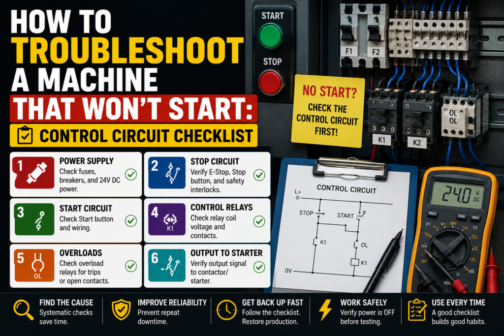
But inside the control panel? Different story. There may be emergency stops, safety relays, motor overloads, start buttons, stop buttons, contactor coils, auxiliary contacts, pressure switches, PLC inputs, PLC outputs, drive enables, interlocks, and five other things quietly saying “nope” in the background.
And, of course, everyone wants it fixed now.
The good news is that a no-start fault can usually be diagnosed step by step. You don’t need to guess. You don’t need to randomly replace parts. You need to follow the control circuit like a trail of breadcrumbs.
This checklist is for industrial machines, motor control panels, and PLC-controlled equipment. Not perfect textbook diagrams. Real panels. Real machines. Real “why is this thing dead again?” situations.
First Question: Is the Machine Dead or Just Not Starting?
Before opening the panel, separate the fault into one of two groups.
Is the whole machine dead?
Or does the machine have power, but refuses to start?
That difference matters a lot.
If the HMI is off, indicator lights are off, PLC has no power, and nothing in the cabinet is alive, you are probably dealing with a main power or control voltage issue.
If the HMI is on, PLC is running, alarms are visible, but the motor or machine cycle does not start, then you’re probably dealing with a control circuit, safety, interlock, or output issue.
Simple split. Very useful.
Ask yourself:
- Is the main power on?
- Is the HMI powered?
- Is the PLC powered?
- Are panel lights working?
- Does the machine show an alarm?
- Does the start button light up?
- Do contactors pull in?
- Does anything click when start is pressed?
- Did it stop suddenly, or did it fail after maintenance/changeover?
That last one is sneaky. If the machine won’t start after someone worked on it, changed a sensor, opened a guard, replaced a motor, cleaned the area, or adjusted a mechanical part, don’t ignore that. Faults love appearing right after “small changes.”
Safety First — Not Just a Nice Phrase
Before measuring anything, remember this: control panels can contain dangerous voltages.
A 24V DC control circuit is usually safer to diagnose than a 400V motor circuit, but both can exist in the same cabinet. So don’t casually reach around live terminals like you’re picking snacks from a bowl.
Use proper lockout/tagout when required. Use insulated tools. Know what voltage you are measuring. Keep one hand away when working near live power. And if you’re not qualified, don’t touch live circuits.
Sounds obvious.
Still worth saying.
A machine that won’t start is annoying. Getting shocked because you rushed is worse.
1. Check the Main Power Supply
Start from the beginning.
Power must enter the cabinet before anything else can happen.
Check:
- Main isolator switch
- Main incoming breaker
- Main fuses
- Phase presence
- Control transformer
- 24V DC power supply
- Control circuit protection breakers
- Neutral and 0V connections
If the machine has a three-phase supply, check that all phases are present. A missing phase can stop the machine or prevent certain devices from working correctly.
Typical checks:
- L1, L2, L3 present
- Correct phase-to-phase voltage
- Correct control voltage
- No tripped breaker
- No blown fuse
- No burnt terminals
- No loose incoming wires
For many European industrial machines, you may see 400V AC three-phase for motors and 24V DC for the control circuit. But don’t assume. Always check the drawing and machine label.
A very common no-start problem is simply missing control voltage.
The machine may have main power, but the 24V DC circuit is dead. In that case, the PLC inputs may not work, safety relay may not reset, sensors may not switch, and contactor coils may never receive a command.
Good sign:
- 24V DC supply is stable, usually around 24V DC
Bad signs:
- 0V on the 24V supply
- Voltage drops when start is pressed
- Power supply cycling on and off
- Control fuse blown
- Miniature breaker tripped
- Burnt smell near power supply
Do not trust only the LED on the power supply. Measure it with a multimeter.
The little green light can lie. Well, not exactly lie, but it can make things look healthier than they are.
2. Check Emergency Stop Buttons
If a machine will not start, emergency stops are one of the first things to check.
Not because they fail every day, but because they are designed to block the start circuit completely.
Check every emergency stop button on the machine:
- Operator panel E-stop
- Rear-side E-stop
- Maintenance station E-stop
- Conveyor E-stop
- Remote station E-stop
- Pendant E-stop
- Any hidden or rarely used E-stop
A classic problem: one emergency stop is pressed somewhere on the back of the machine, and nobody notices. The front panel looks normal, but the safety circuit is open.
Some E-stop buttons twist to release. Some pull to release. Some have key release. Check properly.
Then check the safety relay or safety PLC.
Most safety relays have LED indicators for input channels and output status. If the E-stop chain is healthy, the safety relay should show that both channels are OK and the safety outputs are enabled after reset.
Bad signs:
- One safety channel missing
- Safety relay not resetting
- Safety output off
- E-stop feedback missing
- Safety fault shown on HMI
- Reset button has no effect
Important: do not bypass the emergency stop circuit. Find the open point. Fix the problem properly.
A machine that starts with a bypassed safety circuit is not repaired. It is dangerous.
3. Check Guard Doors, Safety Switches, and Light Curtains
Many machines won’t start unless all guards are closed and all safety zones are clear.
Check:
- Safety gate switches
- Door interlock switches
- Guard locks
- Light curtains
- Safety scanners
- Safety mats
- Two-hand controls
- Access panels
- Safety rope switches
A door may look closed but still not activate the safety switch. Maybe the latch is slightly misaligned. Maybe the actuator tongue is bent. Maybe someone slammed the door and now the switch is half-dead.
It happens.
For light curtains, check whether the beam is blocked. Dust, product pieces, cable ties, brackets, tools, gloves, even a badly positioned part can block the beam.
Good signs:
- Safety switch LEDs show closed/locked
- Light curtain receiver shows clear
- Safety relay channels are healthy
- HMI says safety OK
Bad signs:
- Door closed but safety input off
- Light curtain blocked
- Guard lock not engaging
- Safety reset unavailable
- One channel OK, one channel missing
If the machine has a safety diagnostic page, use it. It may directly show which guard or zone is stopping the start sequence.
That is much faster than walking around the machine guessing.
4. Check the Stop Button Circuit
The stop button is usually normally closed.
That means the circuit is closed when the button is not pressed, and opens when the button is pressed.
If the stop button contact is faulty, loose, or wired incorrectly, the machine may think stop is pressed all the time.
Check:
- Stop button contact block
- Wiring to the stop circuit
- Loose terminal
- Broken wire
- Correct NC contact used
- PLC input status, if stop is monitored by PLC
A very simple test is to measure whether voltage passes through the stop circuit when the button is released.
Good sign:
- Stop circuit closed when button is released
- Stop input healthy
- No alarm from stop circuit
Bad sign:
- Open circuit even when button is released
- Damaged contact block
- Loose wire on stop button
- Wrong contact type used after replacement
This happens more often after someone changes a pushbutton. They accidentally use a normally open contact instead of normally closed, or they connect the wrong terminals.
The button looks perfect from the front. Inside? Chaos in a tiny plastic block.
5. Check the Start Button
After checking the stop circuit, check the start command.
The start button is usually normally open. It closes only when pressed.
Check:
- Mechanical movement
- Contact block condition
- Voltage before and after the contact
- PLC input status
- Loose wires
- Button illumination, if used
- HMI start command, if start is on touchscreen
When you press the start button, the PLC input or control relay should receive the signal.
If nothing changes, the start signal is not reaching the control system.
Possible causes:
- Faulty start button contact
- No voltage feeding the button
- Broken wire
- Loose terminal
- Wrong contact block
- PLC input problem
- Input common missing
- HMI button not sending command
Good sign:
- Start input turns ON when the button is pressed
- Voltage appears at the correct terminal
- PLC sees the start request
Bad sign:
- Button clicks but no electrical signal
- Start input always OFF
- Start input always ON
- Voltage missing before the button
- Voltage present before button but not after pressing
If the start command reaches the PLC but the machine still does nothing, the problem is probably not the physical start button. The PLC may be blocking the start because another condition is missing.
That is where interlocks come in.
6. Check Machine Ready Conditions
A machine usually needs several conditions before it accepts a start command.
Common ready conditions include:
- Safety circuit OK
- Emergency stops released
- Guard doors closed
- Air pressure OK
- No active alarms
- Motor overloads reset
- Drives ready
- Servo enabled
- Machine homed
- Auto mode selected
- Manual mode not active
- Product in correct position
- Temperature reached
- Hydraulic pressure OK
- Lubrication OK
- Communication healthy
The start button may work perfectly, but if one ready condition is missing, the machine will ignore it.
This is where the HMI can save a lot of time.
Look for screens called:
- Machine status
- Start conditions
- Interlocks
- Ready signals
- Diagnostics
- I/O status
- Alarm list
If the HMI shows “Machine not ready,” don’t just keep pressing start. Find out why.
A good machine program should tell you the missing condition. Unfortunately, not every machine has good diagnostics. Some just sit there in silence like a moody teenager.
Then you need to use the drawings and PLC status.
7. Check Motor Overload Relays
If a motor won’t start, check the overload relay.
Motor overload relays are designed to trip when the motor draws too much current for too long. When tripped, they often open a normally closed auxiliary contact in the control circuit.
That open contact can prevent the contactor from energizing.
Check:
- Overload trip indicator
- Reset button position
- Manual/auto reset setting
- Auxiliary contact
- Motor protection breaker
- Current setting
- Burnt or damaged terminals
- Cause of overload
Do not just reset the overload and walk away.
Ask why it tripped.
Possible reasons:
- Mechanical jam
- Motor overloaded
- Conveyor stuck
- Bearing failure
- Pump blocked
- Wrong overload setting
- Phase loss
- Motor cable issue
- Motor winding problem
Good sign:
- Overload is not tripped
- NC auxiliary contact is closed
- Current setting matches motor rating
Bad sign:
- Overload tripped
- Auxiliary contact open
- Trips again after reset
- Burn marks
- Motor hot
- Mechanical load difficult to move
If the overload trips again immediately, don’t keep resetting it. That is not troubleshooting. That is asking for smoke.
8. Check the Contactor Coil Circuit
If the machine uses a motor contactor, the contactor coil must receive the correct voltage to pull in.
Common coil voltages include 24V DC, 24V AC, 110V AC, or 230V AC, depending on the machine.
Check the contactor coil label before measuring.
Then check:
- Coil voltage when start is pressed
- A1 and A2 terminals
- Coil resistance
- Control fuse
- Safety relay output
- PLC output
- Overload NC contact
- Stop circuit
- Auxiliary holding contact
- Loose terminals
Good sign:
- Correct voltage reaches the coil
- Contactor pulls in cleanly
- Auxiliary contact changes state
- Motor starts
Bad sign:
- No voltage at coil
- Low voltage at coil
- Coil receives voltage but does not pull in
- Contactor buzzes
- Contactor pulls in and drops out
- Burnt coil smell
- Mechanical part stuck
If voltage reaches the coil but the contactor does not pull in, the contactor coil may be faulty or the contactor mechanism may be stuck.
If voltage does not reach the coil, trace backward through the control circuit.
Do not replace the contactor before checking whether the coil is actually being powered. A contactor cannot pull in on good intentions.
9. Check the Holding Circuit
In a classic start/stop motor circuit, the start button energizes the contactor coil, and an auxiliary contact keeps the coil energized after the start button is released.
This is called a seal-in or holding circuit.
If the machine starts only while you hold the start button, then stops immediately when you release it, the holding circuit may be faulty.
Check:
- Contactor auxiliary contact
- Holding contact wiring
- Stop circuit
- Overload contact
- Control voltage
- PLC run command, if PLC-controlled
- Relay contacts in the holding path
Good sign:
- Contactor stays energized after releasing start
- Auxiliary contact closes properly
- Control voltage remains stable
Bad sign:
- Contactor drops out after start release
- Auxiliary contact not closing
- Wrong auxiliary contact used
- Loose wire in holding circuit
- PLC removes run command immediately
In PLC-controlled machines, the “holding circuit” may be inside the PLC logic instead of physical wiring. In that case, monitor the start input, run latch, stop input, fault bits, and output command.
Same idea, different location.
10. Check PLC Inputs
If the machine is controlled by a PLC, check whether the PLC sees the start conditions.
Inputs to check:
- Start button
- Stop button
- Emergency stop status
- Safety relay feedback
- Guard closed
- Auto/manual selector
- Reset button
- Air pressure switch
- Overload feedback
- Drive ready
- Home position sensors
- Product present sensor
A PLC can only react to the signals it receives.
If a sensor is physically active but the PLC input is off, the PLC does not know the condition is true.
Check both sides:
- Device LED
- PLC input LED
- Voltage at input terminal
- Wiring and terminal numbers
- Input common
- PLC diagnostics
Example:
The air pressure is fine on the gauge, but the PLC air pressure input is off. Maybe the pressure switch is faulty. Maybe the switch is adjusted too high. Maybe the wire is broken. Maybe the input common is missing.
The PLC is not being stubborn. It is just waiting for a signal.
And machines can wait forever.
11. Check PLC Outputs
If all inputs are ready and the PLC receives the start command, the next question is:
Is the PLC sending an output?
Common outputs:
- Main contactor command
- Motor starter command
- Drive enable
- Servo enable
- Solenoid valve
- Brake release
- Run lamp
- Safety reset command
- Relay coil
Check:
- PLC output LED
- Voltage at output terminal
- Output common supply
- Relay module
- Interposing relay
- Contactor coil
- Drive input
- Wiring to the device
A common trap: the PLC output LED is ON, but the device still does not receive voltage.
Why?
Because the output common is missing, a fuse is blown, a relay contact is bad, or the wiring is open.
Good sign:
- PLC output turns ON
- Correct voltage appears at device
- Device responds
Bad sign:
- PLC output ON but no voltage at device
- Output LED OFF even though start conditions are met
- Voltage at PLC output but not at coil
- Relay clicks but contact does not pass voltage
- Output module fault
Follow the signal step by step.
PLC output → terminal → relay → fuse → device coil.
Somewhere in that path, the voltage disappears. Find that point.
12. Check Safety Relay Outputs
Safety relays often control power to contactor coils, drive enables, or output enable circuits.
A machine may have normal PLC outputs working, but safety relay outputs disabled. In that case, the PLC can request start all day long and still nothing will move.
Check:
- Safety relay input LEDs
- Reset LED
- Safety output LEDs
- Feedback loop
- Contactor feedback contacts
- External device monitoring
- Dual-channel input status
- Safety PLC diagnostics
Some safety systems require feedback from contactors before allowing reset. If a contactor auxiliary contact is stuck or wired incorrectly, the safety relay may refuse to enable.
Good sign:
- Safety relay reset successful
- Safety outputs active
- Feedback loop healthy
Bad sign:
- Safety relay won’t reset
- One channel missing
- Feedback fault
- Safety outputs off
- EDM loop open
This can feel confusing at first, because the emergency stops and doors may all look OK, but the safety relay still says no.
That usually means feedback, reset, or channel mismatch.
13. Check Drives and VFD Enable Signals
If the machine uses a VFD or servo drive, the motor may not start because the drive is not ready.
Check the drive display.
Do not ignore fault codes. They are there for a reason.
Check:
- Drive powered
- Fault code
- Ready signal
- Enable input
- Run command
- Speed reference
- Safe torque off input
- Communication status
- Motor cable
- Parameter lockout
- Local/remote mode
Common reasons a VFD does not start:
- Active fault
- No enable signal
- STO circuit open
- No run command
- Wrong control mode
- Speed reference is 0
- Communication fault
- Drive in local mode
- Motor overload
- DC bus fault
For servo drives, also check:
- Servo alarm
- Encoder cable
- Brake release
- Home sensor
- Limit switches
- Axis enabled
- Following error
- Safety torque off
A drive may be powered and still not ready. Powered is not the same as enabled.
That sentence alone can save time.
14. Check Air Pressure, Hydraulic Pressure, and Utilities
Not every no-start problem is electrical.
Many machines block starting if utilities are missing.
Check:
- Compressed air pressure
- Hydraulic pressure
- Vacuum level
- Cooling water
- Lubrication
- Material supply
- Temperature
- Extraction system
- Pump running
- Valve positions
If the machine has a pressure switch connected to the PLC, check whether that signal is present.
A pneumatic machine with no air may show nothing more than “not ready.” The PLC may simply refuse to begin the cycle.
Good sign:
- Pressure is within machine range
- Pressure switch input is ON
- No utility-related alarm
Bad sign:
- Low air pressure
- Closed air valve
- Leaking hose
- Pressure switch off
- Hydraulic pump not running
- Vacuum not reached
After maintenance or cleaning, someone may close the air valve and forget it.
Yes, it really can be that simple.
And yes, it can still take 30 minutes if nobody checks it.
15. Check Auto/Manual Selector and Mode Conditions
Machines often behave differently depending on mode.
Check:
- Auto/manual switch
- Local/remote switch
- Maintenance mode
- Setup mode
- Jog mode
- HMI mode selection
- Key switch position
- Teach mode
- Robot mode, if used
The machine may not start because it is not in automatic mode.
Or the motor may not start from the panel because it is set to remote mode.
Or the drive may not accept PLC commands because it is in local keypad mode.
Good sign:
- Correct mode selected
- PLC sees correct mode input
- HMI shows expected mode
Bad sign:
- Selector switch position does not match PLC input
- Machine stuck in manual/setup
- Drive in local mode
- Remote start disabled
- Key switch faulty
Mode problems are annoying because they don’t always look like faults. The machine is not broken; it is just waiting for the correct permission.
16. Check Reset Requirements
Some machines need a reset before start is allowed.
Usually after:
- Emergency stop
- Guard door opening
- Drive fault
- Motor overload
- Air pressure loss
- Servo alarm
- Communication fault
- Cycle timeout
- Safety relay trip
Pressing start before reset may do nothing.
Check:
- Reset button input
- HMI reset function
- Safety reset
- Alarm reset
- Drive reset
- Servo reset
- PLC fault reset logic
Good sign:
- Reset input reaches PLC
- Alarms clear
- Safety relay enables
- Machine ready signal becomes active
Bad sign:
- Reset button not seen by PLC
- Alarm immediately returns
- Safety relay still blocked
- Drive fault stays active
- Machine ready never turns on
If an alarm returns immediately after reset, don’t keep pressing reset like it owes you money. The fault is still active.
Find the active condition.
Control Circuit No-Start Checklist
Use this quick order when a machine won’t start:
- Check if the machine has power
- Main isolator
- Main breaker
- Fuses
- Control voltage
- 24V DC supply
- Check the HMI
- Active alarms
- Alarm history
- Machine status
- Missing start condition
- Check emergency stops
- All E-stops released
- Safety relay inputs healthy
- Safety reset done
- Check guards and light curtains
- Doors closed
- Light curtain clear
- Safety switches aligned
- Guard locks engaged
- Check stop circuit
- Stop button NC contact closed
- No broken wires
- PLC stop input healthy
- Check start signal
- Start button works
- PLC input changes
- HMI start command works
- Check ready conditions
- Air pressure OK
- No alarms
- Drives ready
- Overloads reset
- Auto mode selected
- Check motor overload
- Not tripped
- Auxiliary contact closed
- Correct current setting
- Check contactor coil
- Correct voltage at A1/A2
- Coil pulls in
- No buzzing or burning smell
- Check PLC outputs
- Output command ON
- Voltage at output terminal
- Relay or contactor receiving power
- Check drives
- No active fault
- Enable signal present
- Run command received
- Speed reference available
- Check mechanical blockages
- No jammed product
- No stuck conveyor
- No blocked actuator
- No seized motor load
Good vs Bad Readings
| Check Point | Good Reading / Condition | Bad Reading / Condition |
|---|---|---|
| 24V DC supply | Around 24V DC and stable | 0V, low voltage, voltage drops |
| E-stop circuit | All E-stops released, safety relay healthy | Safety channel open, relay not reset |
| Stop button | NC contact closed when released | Open contact when released |
| Start button | NO contact closes when pressed | No signal change |
| PLC start input | Turns ON when start is pressed | Always OFF or always ON |
| Safety relay output | Output enabled after reset | Output disabled |
| Overload relay | Not tripped, NC contact closed | Tripped, NC contact open |
| Contactor coil | Correct voltage at A1/A2 | No voltage or wrong voltage |
| PLC output | Output ON when start allowed | Output OFF despite ready conditions |
| Drive | Ready, enabled, no fault | Fault active, no enable, STO open |
| Air pressure | Within machine range | Too low, pressure switch off |
Example: Motor Won’t Start
Imagine a conveyor motor won’t start.
The operator presses start. Nothing happens.
Here’s the clean way to troubleshoot it.
First, check the HMI. No alarm? Good, but keep looking.
Check emergency stops and safety relay. Safety OK.
Check 24V DC control voltage. Good.
Press the start button and check the PLC input. The PLC sees the start command.
Now check whether the PLC output for the conveyor turns ON. It does.
Next, measure voltage at the contactor coil. No voltage.
So the PLC output is ON, but the contactor coil is not receiving voltage. Now trace the circuit between the PLC output and coil. You find the motor overload auxiliary contact is open.
The overload has tripped.
Now you check why. Conveyor belt is jammed with product.
That is the real fault.
Not the PLC. Not the start button. Not the contactor.
A jammed conveyor caused overload trip, which opened the control circuit, which stopped the motor from starting.
That’s troubleshooting. Follow the chain and the story starts making sense.
Common Mistakes When a Machine Won’t Start
The first mistake is blaming the PLC immediately.
The PLC may be blocking the start because it is missing a required input. That does not mean the PLC is faulty. It means the PLC is doing exactly what the program tells it to do.
The second mistake is replacing the start button without checking the signal. A button can look bad, feel bad, and still work. Or it can look perfect and be electrically dead. Measure it.
The third mistake is ignoring safety feedback. A safety relay may not reset because a contactor feedback loop is open, not because an emergency stop is pressed.
The fourth mistake is resetting overloads repeatedly. If an overload trips, there is usually a reason. Find it.
The fifth mistake is staying inside the cabinet too long. Sometimes the electrical fault is actually mechanical. A stuck conveyor, blocked cylinder, or bent sensor bracket can stop the whole start sequence.
Control circuits are not magic. They are chains.
When the chain breaks, the machine won’t start.
Your job is to find which link opened.
Final Thoughts
When a machine won’t start, don’t panic and don’t jump straight to replacing parts.
Start with power. Then safety. Then stop and start circuits. Then ready conditions. Then PLC inputs and outputs. Then contactors, overloads, drives, and mechanical load.
The order matters.
A no-start fault becomes much easier when you treat it like a control circuit path instead of a mystery. Power must reach the control system. Safety must allow operation. The start signal must reach the PLC or relay logic. The output must energize the contactor or drive. The motor or actuator must move. Feedback must confirm that it happened.
That’s the whole game, really.
Follow the voltage. Follow the signal. Follow the logic.
And before blaming the PLC, check the emergency stop hiding on the back side of the machine. There’s always one.