The machine is stopped. The emergency stop has been released. The guard door is closed. The operator presses reset.
Nothing.
No click from the safety relay. No “machine ready” light. No green start button. Just that annoying dead silence from the control panel.
And then somebody says:
“Maybe the PLC is bad.”
Probably not.
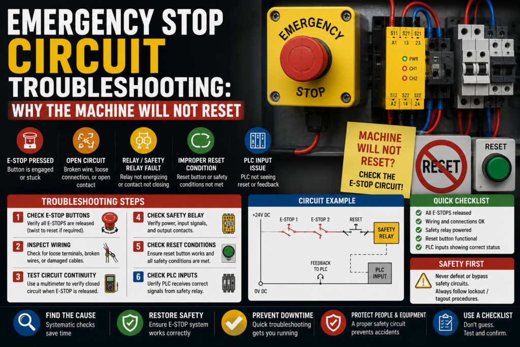
When a machine will not reset after an emergency stop, the problem is usually in the safety circuit or one of the reset conditions around it. An E-stop button might still be pressed. A guard switch may not be made. A light curtain may be blocked. A safety relay may be waiting for feedback. A contactor auxiliary contact may be stuck. The reset button may not be sending the signal. Or one channel of a dual-channel safety circuit may be open while the other one looks fine, which is always a nice little trap.
Emergency stop circuit troubleshooting is not about guessing. And definitely not about bypassing safety devices “just for a quick test.”
It is about following the safety chain carefully.
Because if the safety circuit will not reset, it is usually saying one thing:
Something is still not safe, not proven safe, or not being detected correctly.
First: What Does “Will Not Reset” Mean?
Before opening the panel, define the symptom properly.
A reset problem can look like several different things:
- Safety relay will not reset
- Safety relay resets, then drops out immediately
- Reset button does nothing
- Safety relay input LEDs are not healthy
- One E-stop channel is missing
- Machine reset works only sometimes
- Reset works with one door, but not another
- HMI says “safety circuit not ready”
- HMI says “emergency stop active” even when all buttons are released
- Start button is ignored after reset
- Safety PLC shows a zone fault
- Contactor feedback fault blocks reset
These are not all the same fault.
If the safety relay never enables, start with E-stops, guard switches, light curtains, reset wiring, and supply voltage.
If it enables and immediately drops, think feedback loop, contactor monitoring, channel mismatch, unstable supply, or a safety device bouncing.
If the reset button does nothing, check whether the safety relay is even ready to accept reset.
Small difference. Big time saver.
Safety First — Seriously
Emergency stop circuits are safety-related circuits.
So don’t bypass them to make production run.
That sentence should not need to be said, but in real factories, pressure exists. Downtime costs money. People get impatient. Someone says, “Just bridge it quickly so we can finish the batch.”
No.
An emergency stop circuit is there because moving machinery can hurt people. If it will not reset, find the reason. Do not defeat the protection.
Before testing:
- Follow lockout/tagout rules
- Know what voltage you are measuring
- Use the electrical drawing
- Use a proper multimeter
- Keep clear of moving parts
- Do not bypass E-stops, guard switches, light curtains, or safety relay outputs
- Do not force contactors or actuators manually
- Test the machine safely after repair
You can troubleshoot safely. You can measure. You can inspect. You can isolate. But do not create a dangerous machine just to prove a point.
A machine that runs with a bypassed safety circuit is not fixed.
It is dangerous.
1. Check All Emergency Stop Buttons
Start with the obvious one.
Then check the not-obvious ones.
Machines often have more E-stop buttons than people remember:
- Main operator panel E-stop
- Rear side E-stop
- Conveyor E-stop
- Maintenance station E-stop
- Robot cell E-stop
- Pendant E-stop
- Remote HMI E-stop
- Packaging section E-stop
- Palletizer or feeder E-stop
- Safety rope switch
One E-stop button left pressed somewhere on the back side of the machine can block the whole reset.
Classic.
Check each emergency stop physically.
Some twist to release. Some pull to release. Some require a key. Some look released but the contact block behind the button is damaged or not returning properly.
Good signs:
- E-stop button is fully released
- Mechanical movement feels normal
- Safety relay input channels become healthy
- HMI no longer shows E-stop active
Bad signs:
- Button stuck
- Button head released but contact still open
- Broken contact block
- Loose wire behind button
- One channel missing
- E-stop feels soft, jammed, or damaged
- HMI still shows E-stop active
Do not only look at the front of the button. If the contact block has come loose behind the panel, the button may look fine but the circuit stays open.
The front smiles. The back betrays you.
2. Check the Safety Relay LEDs
Most safety relays give useful diagnostic information with LEDs.
Look for LEDs such as:
- Power
- Channel 1
- Channel 2
- Input 1
- Input 2
- Reset
- Output
- Fault
- EDM
- K1/K2
- Safety output
The exact labels depend on the safety relay brand, but the idea is similar.
You want to know:
- Is the safety relay powered?
- Are both input channels healthy?
- Is the reset input being received?
- Are the safety outputs switching on?
- Is there a feedback or EDM fault?
- Is the relay detecting a channel mismatch?
Good signs:
- Power LED on
- Both channels healthy
- Reset signal accepted
- Safety outputs active
- No fault LED
Bad signs:
- No power
- Only one channel healthy
- Fault LED active
- Reset LED not changing
- Outputs stay off
- EDM or feedback fault
- Relay resets then drops out
A safety relay with one good channel and one missing channel will usually not reset. That is the whole point of dual-channel monitoring.
Don’t assume “one side works” means the E-stop circuit is fine.
In safety circuits, half-good is usually not good.
3. Check 24V DC Supply to the Safety Circuit
Many modern safety relays, guard switches, light curtains, and safety PLCs use 24V DC.
If the 24V supply is missing or unstable, the safety circuit may refuse to reset.
Check:
- 24V DC at the safety relay
- 0V common
- Safety device supply
- E-stop channel supply
- Guard switch supply
- Light curtain transmitter and receiver supply
- Reset button supply
- Control fuses or electronic breakers
- Loose 0V terminals
- Power supply overload
Measure between +24V and 0V, not random terminals.
Good signs:
- Stable 24V DC
- Safety relay powered
- Safety devices powered
- No flickering LEDs
Bad signs:
- 0V at safety relay
- Low voltage
- Voltage drops when reset is pressed
- Safety relay restarts
- Power LED flickers
- Control fuse blown
- 0V common loose
If the safety relay power LED flickers or the relay clicks on and off, check the power supply before blaming the safety relay.
A weak 24V supply can create very confusing safety faults.
Very confusing. Very annoying.
4. Check Guard Doors and Safety Switches
A machine may not reset if any guard door is open or not detected as closed.
Check:
- Guard door safety switches
- Door interlock switches
- Locking safety switches
- Magnetic safety switches
- RFID safety switches
- Hinged safety switches
- Mechanical tongue switches
- Access panels
- Service doors
A door can look closed and still not satisfy the safety switch.
Possible reasons:
- Door not fully closed
- Actuator misaligned
- Switch bracket bent
- Tongue not entering switch correctly
- Safety switch damaged
- Cable broken
- Connector loose
- Lock not engaged
- Wrong actuator used after replacement
- Safety switch not taught/paired, on coded switches
Good signs:
- Door closed LED active
- Lock LED active, if locking switch
- Safety relay channels healthy
- HMI shows guard closed
Bad signs:
- Door physically closed but input off
- Switch LED red or flashing
- Lock not engaging
- Door actuator bent
- Loose mounting screws
- Guard switch cable damaged
- HMI still shows door open
This is one of the most common reset problems after mechanical maintenance.
Someone adjusts a door, changes a hinge, bends a bracket slightly, and suddenly the safety switch is 2 mm out of alignment.
Two millimeters. Whole machine dead.
Industrial comedy.
5. Check Light Curtains and Safety Scanners
If the machine uses light curtains or safety scanners, check that the protected area is clear.
Look for:
- Blocked light curtain beam
- Dirty lens
- Misalignment
- Receiver fault
- Transmitter fault
- Loose mounting
- Damaged cable
- Muting fault
- Reset required after interruption
- Safety scanner zone blocked
- Scanner lens dirty
- Wrong scanner field selected
A light curtain may block reset even if no person is inside the area.
A hanging cable tie, a part, dust, a bracket, a pallet, or even bad alignment can interrupt the beam.
Good signs:
- Light curtain shows clear/green
- Receiver sees transmitter
- Safety output active
- No muting fault
- Scanner protective field clear
Bad signs:
- Beam blocked
- Dirty lens
- Red fault LED
- Misaligned transmitter/receiver
- Scanner zone occupied
- Muting lamp fault, if monitored
- Safety output off
Clean the lenses if needed. Check alignment. Check the diagnostic LEDs.
Do not tape a reflector in place and hope. Do not bypass scanner outputs. Don’t do circus repairs.
Find the reason it is not clear.
6. Check the Reset Button
The reset button itself may be faulty.
Usually, reset is a normally open pushbutton. When pressed, it sends a reset signal to the safety relay or safety PLC.
Check:
- Button mechanical movement
- Contact block condition
- Voltage before the button
- Voltage after the button when pressed
- Safety relay reset input
- PLC reset input, if used
- Loose terminals
- Wrong contact block
- Broken wire
- HMI reset button, if touchscreen reset is used
Good signs:
- Reset signal changes when pressed
- Safety relay sees reset input
- Button returns normally
- Contact closes only when pressed
Bad signs:
- Button clicks but no electrical signal
- Reset input never changes
- Wrong contact type installed
- Loose wire
- Button stuck
- Reset signal permanently on
- Contact block fallen off
A reset signal stuck permanently ON can also be a problem.
Some safety relays require a reset pulse, not a reset signal that is already active before the safety inputs become healthy. So if the reset button is stuck or wired incorrectly, the relay may refuse to reset.
Yes, the reset button can be “too on.”
Because safety circuits like things done in the correct order.
7. Check Manual Reset vs Automatic Reset Settings
Some safety relays can be configured for manual reset or automatic reset.
Manual reset means the relay requires a reset button press after the safety inputs become healthy.
Automatic reset means the relay enables automatically when safety inputs are healthy.
Many machines use manual reset because it prevents automatic restart after a safety interruption.
Check:
- Safety relay wiring
- Reset mode jumper
- DIP switch settings
- Configuration software, if safety controller
- Machine safety design requirements
- Electrical drawing
If the relay is set for manual reset, it will not enable just because the E-stop is released.
If the relay is set incorrectly after replacement, reset behavior may change.
Good signs:
- Reset mode matches machine design
- Wiring matches safety relay manual
- Reset works only when safety inputs are healthy
Bad signs:
- Wrong reset mode
- Missing reset jumper
- Reset input wired incorrectly
- Replacement relay configured differently
- Reset works unexpectedly or not at all
Do not change reset mode just to make the machine run.
The reset mode is part of the safety design.
If you are not responsible for safety validation, don’t casually modify it.
8. Check Dual-Channel E-Stop Wiring
Many E-stop circuits use two channels.
For example:
- Channel 1 through one NC contact
- Channel 2 through another NC contact
The safety relay compares both channels. If one opens and closes differently from the other, it may detect a fault.
Check:
- Channel 1 voltage/path
- Channel 2 voltage/path
- Both E-stop contact blocks
- Wire continuity
- Terminal numbers
- Cross-fault detection wiring
- Shorts between channels
- Shorts to +24V or 0V
- Correct NC contacts used
Good signs:
- Both channels open when E-stop is pressed
- Both channels close when E-stop is released
- Relay sees both channels healthy
- No channel mismatch
Bad signs:
- One channel closed, one channel open
- One contact block stuck
- Wrong contact type used
- Channels shorted together
- Channel fault LED active
- Relay refuses reset after E-stop cycle
This is a big one.
If someone replaces an E-stop contact block and wires only one channel correctly, the circuit may look partly healthy but still not reset.
In safety troubleshooting, always check both channels.
Not the one that is easiest to reach.
Both.
9. Check for Channel Mismatch After Reset
Some safety relays monitor the timing between channels.
If one channel closes much later than the other, or one channel stays open, the relay may detect a mismatch.
Possible causes:
- Worn E-stop contact
- Sticky guard switch
- Damaged safety switch
- Loose connector
- Slow mechanical door lock
- Broken actuator
- Bad contact block
- Wiring fault
- One channel bypassed incorrectly in the past
Good signs:
- Both channels change together
- Relay accepts reset
- No fault LED
Bad signs:
- One channel flickers
- One channel closes late
- Relay faults after E-stop release
- Reset works sometimes
- Safety input LED unstable
Intermittent channel mismatch can be frustrating because the machine may reset sometimes and fail other times.
Watch the safety relay LEDs while operating the E-stop or guard.
If one channel LED flickers or lags, follow that channel.
The LED is telling you where to look.
10. Check the Feedback Loop / EDM Circuit
This is one of the sneakiest reasons a machine will not reset.
Many safety relays monitor external devices, usually contactors, through a feedback loop. This is often called:
- EDM
- External Device Monitoring
- Feedback loop
- Contactor feedback
- K1/K2 monitoring
- Safety output feedback
The idea is simple.
Before the safety relay resets, it checks that the contactors it controls are actually in the off state. If a contactor is welded, stuck, or feedback wiring is wrong, the safety relay refuses to enable.
Check:
- Contactor auxiliary NC contacts
- Safety contactor feedback wiring
- K1/K2 auxiliary contacts
- EDM terminals
- Feedback loop continuity
- Stuck/welded contactor
- Wrong auxiliary contact type
- Loose wire
- Replacement contactor feedback wiring
Good signs:
- Feedback loop closed when contactors are de-energized
- Feedback opens when contactors energize
- Safety relay accepts reset
- Contactors move correctly
Bad signs:
- Feedback loop open before reset
- Contactor auxiliary contact stuck
- Wrong NO/NC contact used
- Safety relay shows EDM fault
- One contactor welded or mechanically stuck
- Feedback wiring missing after replacement
Example:
The emergency stops are released. All guard doors are closed. Light curtain is clear. Reset button works.
But the safety relay still refuses to reset.
Then you check the feedback loop and find one contactor auxiliary NC contact is open because the contactor is stuck or the wrong auxiliary contact was installed.
The safety relay is not being annoying.
It is doing exactly what it should: refusing to enable a circuit when it cannot prove the output devices are safe.
11. Check Safety Contactors
Safety relays often control two contactors in series, especially for motor power or actuator power.
If one safety contactor fails mechanically or electrically, reset may be blocked.
Check:
- K1 and K2 contactors
- Coil voltage
- Auxiliary feedback contacts
- Mechanical movement
- Welded main contacts
- Stuck armature
- Overheated coil
- Loose terminals
- Contactor feedback wiring
Good signs:
- Contactors are de-energized before reset
- Auxiliary feedback contacts show correct state
- Contactors pull in cleanly after reset
- No mechanical sticking
Bad signs:
- Contactor stuck closed
- Contactor auxiliary contact not changing
- Coil damaged
- Contactor chatters
- Feedback fault
- Burn marks
- Contactors do not drop out properly
If the safety circuit detects that a contactor did not drop out correctly, it may block the next reset.
That is not a nuisance fault.
That is a serious warning.
A welded contactor in a safety circuit must be handled properly.
12. Check Safety Relay Output Circuit
Sometimes the safety relay resets correctly, but the machine still says “not reset” because the safety output is not reaching the next part of the circuit.
Check:
- Safety output terminals
- Output fuses
- Wiring after safety relay
- Contactor coils
- Drive STO inputs
- PLC safety feedback input
- Terminal blocks
- Jumpers
- Safety output expansion modules
Good signs:
- Safety relay outputs close after reset
- Voltage reaches contactor coils or STO inputs
- PLC sees safety OK input
- Machine ready light turns on
Bad signs:
- Safety relay output LED on, but no voltage after output
- Bad output contact
- Blown fuse after relay
- Broken wire
- PLC safety OK input missing
- Drive STO still open
- Expansion relay not energized
Measure carefully.
The safety relay may be working, but the downstream signal may be missing.
That creates a confusing situation: the safety relay looks reset, but the machine still will not start.
13. Check Drive STO Inputs
Modern VFDs and servo drives often use STO — Safe Torque Off.
Even if the safety relay resets, the machine may not become ready if the drive STO inputs are not satisfied.
Check:
- STO channel 1
- STO channel 2
- Safety relay output to STO
- Drive STO status
- Drive fault code
- Wiring to STO terminals
- STO reset requirement
- Drive enable signal
- Drive ready feedback
Good signs:
- Both STO channels active
- Drive shows ready
- No STO fault
- PLC receives drive ready signal
Bad signs:
- One STO channel missing
- Drive shows STO active
- STO fault remains after reset
- Safety output reaches one channel but not the other
- Drive ready signal missing
A machine may reset the main safety relay but still refuse to start because one drive still has STO active.
So check the drive display too.
The safety circuit does not always end at the safety relay.
14. Check Safety PLC Diagnostics
If the machine uses a safety PLC, the HMI or engineering software may show exactly which safety input is blocking reset.
Check:
- Active safety faults
- Input channel status
- Guard zones
- E-stop zones
- Light curtain status
- Reset request status
- Output status
- Feedback monitoring
- Discrepancy time faults
- Wiring cross-faults
- Safety program diagnostics
Good signs:
- All safety inputs healthy
- Reset request detected
- Safety outputs active
- No active safety faults
Bad signs:
- Zone fault
- Channel discrepancy
- Reset input not detected
- Output feedback fault
- Cross-circuit fault
- Safety task fault
- Device communication fault
With safety PLCs, don’t guess from terminal LEDs only if diagnostics are available.
Use the diagnostic page.
A safety PLC may tell you plainly: “Door 3 channel B missing.”
That is much better than walking around the machine poking every switch like a confused woodpecker.
15. Check Wiring, Terminals, and Connectors
Safety circuits often run through many devices, terminals, and connectors.
One loose wire can break the reset chain.
Check:
- E-stop terminals
- Guard switch connectors
- Safety relay terminals
- Reset button terminals
- Feedback loop terminals
- Contactor auxiliary contacts
- Terminal jumpers
- M12 safety connectors
- Cabinet door wiring
- Cable glands
- Moving cable chains
- Junction boxes
Look for:
- Loose screws
- Broken ferrules
- Pulled wires
- Crushed cables
- Oil or water in connectors
- Corrosion
- Bent pins
- Damaged insulation
- Wrong terminal numbers
- Recent rewiring
Good signs:
- Wires tight
- Terminal numbers match drawing
- No corrosion
- No damaged cables
- Connectors dry and secure
Bad signs:
- Wire pulls out easily
- Connector loose
- Broken wire near moving hinge
- Water inside junction box
- Corroded safety switch plug
- Cabinet door wire broken
- Recently replaced part wired differently
Cabinet door wiring is especially suspicious.
E-stop and reset buttons are often mounted on doors. Open and close the panel enough times over years, and wires can fatigue.
The fault appears “random.”
It is not random. It is a wire bending 20,000 times and finally giving up.
16. Check the HMI Reset and Alarm Reset Logic
On some machines, there are two different resets:
- Safety reset
- Alarm reset
- Fault reset
- Drive reset
- Cycle reset
- Servo reset
Releasing the E-stop may require a safety reset. But after that, the machine may still need alarm reset before it becomes ready.
Check:
- Safety reset button
- HMI reset button
- Alarm reset input
- Drive reset output
- PLC reset logic
- Machine ready conditions
- Active alarms still present
Good signs:
- Safety relay resets
- Alarms clear
- Machine ready bit turns on
- Start command accepted
Bad signs:
- Safety OK but active alarms remain
- HMI reset not working
- PLC reset input missing
- Drive fault still active
- Servo alarm still active
- Machine not homed after reset
Sometimes people say “the safety circuit will not reset,” but the safety relay is actually reset. The real issue is that the PLC still blocks machine start because another fault is active.
So separate these two:
Safety reset means the safety system is healthy and enabled.
Machine reset means the PLC has cleared faults and is ready to run.
Different things.
Often mixed up.
17. Check Safety Device Replacement Issues
A lot of reset problems appear after replacing a safety device.
Maybe someone replaced:
- E-stop button
- Safety relay
- Guard switch
- Light curtain
- Safety PLC module
- Safety contactor
- Door lock
- RFID safety sensor
- Reset button
- Cable or connector
After replacement, check:
- Correct part number
- Correct contact type
- Correct wiring
- Correct reset mode
- Correct device coding/teaching
- Correct alignment
- Correct channel wiring
- Correct feedback wiring
- Correct voltage
- Correct safety relay configuration
Good signs:
- Replacement matches old device
- Wiring matches schematic
- Safety relay diagnostics clear
- Reset works normally
Bad signs:
- Wrong NO/NC contacts
- Wrong actuator
- Wrong safety relay type
- Device not coded
- Channels swapped
- Feedback missing
- Reset wiring different
- DIP switches not set like old relay
Safety components are not always plug-and-play.
A guard switch may need correct actuator alignment. A coded switch may need pairing. A safety relay may need the correct reset wiring. A contactor may need the right auxiliary feedback contact.
Replacing the part is one thing.
Restoring the safety function is the actual repair.
Quick Checklist: Machine Will Not Reset After E-Stop
Use this order when troubleshooting.
- Check all E-stop buttons
- Front panel
- Rear side
- Remote stations
- Rope switches
- Pendants
- Check safety relay power
- 24V DC present
- 0V common good
- Power LED stable
- Check safety relay inputs
- Channel 1 healthy
- Channel 2 healthy
- No channel mismatch
- No fault LED
- Check guard doors
- Doors fully closed
- Switches aligned
- Locks engaged
- HMI shows guards closed
- Check light curtains/scanners
- Beam clear
- Lenses clean
- No zone blocked
- Safety output active
- Check reset button
- Contact closes when pressed
- Reset input reaches relay/PLC
- Button not stuck permanently on
- Check reset mode
- Manual reset wiring correct
- DIP switches/configuration correct
- Replacement relay configured properly
- Check feedback loop / EDM
- Contactor feedback closed before reset
- K1/K2 auxiliary contacts correct
- No welded/stuck contactor
- Check safety outputs
- Relay output closes after reset
- Voltage reaches downstream devices
- Expansion relay works
- Check drive STO
- Both STO channels active
- Drive ready
- No STO fault
- Check PLC/HMI status
- Safety OK bit active
- Alarm reset completed
- No remaining machine faults
- Check wiring
- Loose terminals
- Broken door wires
- Wet connectors
- Damaged cables
- Recent changes
Good vs Bad Signs
| Check Area | Good Sign | Bad Sign |
|---|---|---|
| E-stop buttons | All released, contacts closed | One button pressed, contact stuck open |
| Safety relay power | Stable 24V DC | No power, flickering, low voltage |
| Safety channels | Both channels healthy | One channel missing, mismatch fault |
| Guard switches | Door closed signal active | Door closed but switch not made |
| Light curtain | Clear/green, outputs active | Blocked, dirty, misaligned, red fault |
| Reset button | Reset input changes when pressed | No signal, stuck signal, loose contact |
| Reset mode | Wiring/config matches design | Wrong jumper, wrong DIP switch |
| Feedback loop | Closed before reset | Open EDM loop, stuck contactor |
| Safety outputs | Outputs close after reset | Output off, bad relay contact, blown fuse |
| Drive STO | Both channels satisfied | STO active, one channel missing |
| PLC safety OK | PLC sees safety healthy | Safety OK input missing |
| Wiring | Tight, dry, correct terminals | Loose, wet, broken, miswired |
Example 1: One E-Stop Channel Missing
A machine will not reset after an emergency stop.
All E-stop buttons look released.
The safety relay power LED is on. Channel 1 LED is on. Channel 2 LED is off.
That means the safety relay is not seeing both channels.
You follow channel 2 through the drawing and measure the E-stop contact blocks. One rear-side E-stop has a damaged NC contact. The button head is released, but one contact block stays open.
Cause: faulty E-stop contact block on channel 2.
The button looked fine from the front.
The circuit disagreed.
Trust the circuit.
Example 2: Safety Relay Will Not Reset Because of Feedback
The operator releases the E-stop and closes all doors.
Both safety input channels are healthy.
Reset button works.
But safety relay still will not enable. EDM/feedback LED indicates a fault.
You check the feedback loop through two contactors, K1 and K2.
One contactor auxiliary NC feedback contact is open because the contactor is mechanically stuck.
Cause: safety relay blocks reset because it cannot prove the contactor is off.
That is not a nuisance.
That is exactly why feedback monitoring exists.
Example 3: Guard Door Closed but Machine Says Open
The HMI says “Guard door 2 open.”
The door is physically closed.
You inspect the safety switch. The actuator is slightly misaligned because the door hinge has dropped. The switch does not detect the door every time.
You adjust the mechanical alignment properly and verify the safety input changes correctly.
Cause: mechanical misalignment of guard switch.
Not PLC fault.
Not safety relay fault.
Just a door that aged badly.
Happens to machines too, apparently.
Example 4: Reset Button Does Nothing
A machine will not reset.
The safety relay inputs are healthy. No E-stop active. Guards closed.
You press reset. The safety relay reset input LED never changes.
You measure the reset button circuit. There is 24V before the button, but no voltage after it when pressed.
The contact block is faulty.
Cause: reset button contact failure.
Simple fault. But only obvious after measuring.
Common Mistakes in Emergency Stop Circuit Troubleshooting
The first mistake is checking only one E-stop.
There may be several. Check all of them.
The second mistake is ignoring the second safety channel.
A dual-channel safety circuit needs both channels healthy.
The third mistake is assuming the reset button is good because it clicks.
Mechanical click does not prove electrical contact.
The fourth mistake is forgetting the feedback loop.
If contactor feedback is wrong, the safety relay may refuse to reset even when all E-stops are released.
The fifth mistake is confusing safety reset with machine alarm reset.
The safety circuit may be healthy, but the PLC may still block start because alarms are active.
The sixth mistake is replacing a safety relay before checking inputs, reset, and feedback.
Safety relays do fail, but wiring and field devices are more common.
The seventh mistake is bypassing safety devices.
Don’t.
Really. Don’t.
Tools for Emergency Stop Circuit Troubleshooting
Useful tools:
- Electrical schematic
- Multimeter
- Safety relay manual
- PLC or safety PLC diagnostic software
- Insulated screwdrivers
- Terminal labels
- Known-good reset contact block
- Continuity tester
- HMI diagnostic screen
- Drive display, for STO status
- Spare fuses
- Cable tester, if needed
The best tool is still the drawing.
Follow the circuit:
Safety device → safety relay input → reset input → feedback loop → safety output → PLC/contactor/drive STO.
That chain tells the story.
Final Thoughts
When an emergency stop circuit will not reset, don’t jump straight to replacing the safety relay.
Start simple.
Check every E-stop. Check guard doors. Check light curtains. Check the safety relay LEDs. Check both channels. Check the reset button. Check the feedback loop. Check contactor auxiliary contacts. Check drive STO inputs. Check whether the PLC actually sees “safety OK.”
Most reset problems are not mysterious.
They are open circuits, missing channels, bad contacts, misaligned guards, blocked light curtains, wrong feedback, or wiring faults.
The safety circuit is not trying to annoy you.
Well, it feels like it sometimes.
But its job is to prevent the machine from restarting until the safe conditions are proven.
So follow the chain carefully, measure properly, and never bypass the protection just to make the machine run.
A machine that will not reset is frustrating.
A machine that resets when it should not is much worse.