An encoder fault can be very irritating because the machine may look completely fine.
The motor turns. The roller moves. The belt runs. The shaft spins.
But inside the PLC?
Nothing.
The count stays at zero, jumps randomly, counts backwards, resets for no clear reason, or only counts when you rotate the shaft painfully slowly like you’re cracking a safe in an old movie.
And then someone says, “The encoder is bad.”
Maybe.
But not so fast.
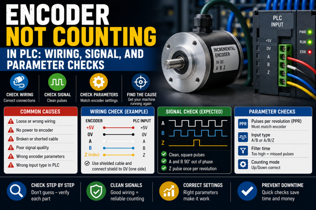
When an encoder is not counting in a PLC, the problem can be wiring, power supply, signal type, high-speed input configuration, wrong PLC parameters, shield grounding, mechanical coupling, or even a simple misunderstanding of which wire is A, B, Z, +V, and 0V.
Encoders are not difficult once you follow the signal properly.
They are just unforgiving.
One wrong input type, one missing 0V common, one disabled high-speed counter, and the PLC sees absolutely nothing.
First: What Type of Encoder Are You Troubleshooting?
Before touching wires, identify the encoder type.
Most PLC counting problems involve an incremental encoder.
An incremental encoder usually sends pulse signals such as:
- A channel
- B channel
- Z channel, sometimes called index
- A-not / B-not / Z-not, on differential encoders
- +V supply
- 0V common
- Shield
The PLC counts the pulses to measure position, speed, length, or movement.
A and B are usually shifted 90 degrees from each other. That phase shift lets the PLC know direction. If A leads B, it counts one direction. If B leads A, it counts the opposite direction.
The Z signal is often one pulse per revolution. It is used for reference, homing, or index detection.
Simple enough.
Until the wire colors don’t match the drawing, the encoder output is line driver but the PLC expects 24V PNP, the high-speed counter is not enabled, and the shield is connected like someone guessed during lunch break.
Lovely.
Common Symptoms When the PLC Does Not Count
Encoder faults do not always look the same.
You may see:
- Count stays at zero
- Count changes only sometimes
- Count jumps randomly
- Count increases but direction is wrong
- Count decreases when it should increase
- Count works slowly but fails at higher speed
- Count resets unexpectedly
- Count is noisy when the motor runs
- Count works with shaft disconnected but not on the machine
- Z pulse is never detected
- PLC sees A but not B
- PLC input LEDs flicker, but counter value does not change
- HMI position value freezes
- Servo or VFD feedback fault appears
- Length measurement is wrong
Those symptoms matter.
A count stuck at zero points toward no signal, wrong wiring, missing supply, wrong input configuration, or dead encoder.
A count that jumps randomly smells more like noise, shielding, grounding, wrong input voltage, loose wiring, or too high pulse frequency.
Wrong direction? Usually A/B swapped or parameter direction inverted.
Works slowly but not fast? High-speed counter setup, input frequency limit, scan time problem, or signal quality issue.
The symptom is already giving clues.
Don’t ignore it.
Safety Before Encoder Testing
Encoders are often mounted on moving shafts, rollers, motors, conveyors, or cutting systems.
So, before testing:
- Lock out the machine when working on wiring
- Keep hands away from rotating shafts
- Do not remove guards while the machine can start
- Be careful with belts, couplings, pulleys, and rollers
- Do not short encoder supply wires
- Do not connect oscilloscope or meter probes where they can get caught
- Follow the machine’s safety procedure
Also, be careful when rotating a motor shaft manually. Some machines can move unexpectedly if brakes release or stored mechanical energy is present.
A small encoder is harmless-looking.
The machine attached to it may not be.
1. Check Encoder Power Supply
Start with power.
No power, no pulses.
Most industrial encoders use one of these supply voltages:
- 5V DC
- 10–30V DC
- 12V DC
- 24V DC
Do not assume it is 24V just because the panel is 24V.
Read the encoder label or datasheet.
Check:
- +V at the encoder
- 0V at the encoder
- Voltage under load
- Correct polarity
- Power supply fuse
- M12 connector pinout
- Cable damage
- Common connection to PLC input module
Good signs:
- Correct supply voltage at encoder terminals
- Encoder power LED on, if available
- Voltage stable while shaft turns
- 0V common connected correctly
Bad signs:
- 0V supply
- Wrong voltage
- Reverse polarity
- Voltage drops when encoder connected
- Fuse blown
- Loose connector
- Encoder gets hot
- Missing common between encoder and PLC
Measure directly at the encoder connector if possible.
It is not enough to measure 24V at the power supply in the cabinet. A broken cable can give you perfect voltage in the cabinet and nothing at the encoder.
That’s how machines waste your afternoon.
2. Check the 0V Common
The encoder and PLC input need a common reference.
This is one of those boring things that causes very strange faults.
If the encoder has power but the PLC input module does not share the correct 0V common, the PLC may not detect pulses properly.
Check:
- Encoder 0V
- PLC input common
- High-speed counter common
- Remote I/O common
- Power supply 0V
- Terminal jumpers
- Broken common wire
Good signs:
- Encoder 0V and PLC input common are tied correctly
- Inputs switch cleanly
- No floating voltage
- Count is stable
Bad signs:
- Encoder output voltage looks correct to encoder 0V but not to PLC common
- PLC input LED does not switch
- Random flickering
- Count unstable
- Floating readings
- Common wire loose or missing
A common mistake is measuring encoder output against the wrong 0V.
Always measure the signal using the same reference the PLC input uses.
The PLC does not care what your meter saw somewhere else. It only sees voltage relative to its input common.
3. Check Encoder Output Type
Encoder output type must match the PLC input type.
Common encoder outputs include:
- PNP / sourcing
- NPN / sinking
- Push-pull
- TTL / 5V
- HTL / 10–30V
- RS-422 differential line driver
- Open collector
This matters a lot.
A 5V TTL encoder connected to a 24V PLC input may not be detected. A differential encoder connected to a normal single-ended input may not work correctly. An NPN encoder connected to an input wired for PNP may do absolutely nothing.
Very rude. But logical.
PNP Encoder
A PNP encoder output switches positive voltage to the PLC input.
Usually:
- Brown = +V
- Blue = 0V
- Black = A
- White = B
- Other color = Z, depending on model
When the output is ON, the PLC input sees +24V or similar.
NPN Encoder
An NPN encoder output switches the PLC input down to 0V.
It needs the PLC input wired with the correct common/supply arrangement.
Differential Line Driver
A differential encoder has signal pairs:
- A and A-
- B and B-
- Z and Z-
These are often used for longer cable runs and better noise immunity.
But the PLC or counter module must support differential inputs.
Good signs:
- Encoder output type matches PLC high-speed input
- Correct wiring for PNP/NPN/differential
- Signal voltage matches input specification
- PLC input LEDs behave as expected
Bad signs:
- 5V encoder connected to 24V-only input
- Differential encoder wired into basic digital inputs incorrectly
- NPN/PNP mismatch
- Open collector output has no pull-up
- Wrong common wiring
- Signal voltage too low for PLC input threshold
This is one of the first things to check after encoder replacement.
The new encoder may physically fit perfectly and still have the wrong electrical output.
A beautiful wrong part.
4. Check A and B Signal Wiring
For counting with direction, the PLC usually needs both A and B signals.
Check:
- A channel wired to correct PLC input
- B channel wired to correct PLC input
- A/B not swapped, unless direction is intentionally reversed
- Wires not broken
- Terminal numbers correct
- M12 pinout correct
- Shield not used as 0V by mistake
- No loose ferrules
- No damaged cable
If A and B are swapped, the PLC may count in the opposite direction.
That is not always a fault. Sometimes you can fix direction in the PLC parameter. But first know what changed.
Good signs:
- A and B signals switch when shaft rotates
- PLC high-speed counter sees both channels
- Direction is correct
- Count increases/decreases smoothly
Bad signs:
- A switches, B does not
- B switches, A does not
- A/B swapped unexpectedly
- One channel stuck high or low
- Input LED flickers but no count changes
- Count direction wrong
- Count jumps forward/backward randomly
If the PLC only receives channel A, it may count pulses but not direction, depending on configuration.
If the PLC is configured for A/B quadrature but only A is connected, it may not count correctly.
Configuration and wiring must agree.
That sounds obvious until you see a machine where they don’t.
5. Check the Z / Index Signal
The Z channel is usually one pulse per revolution.
It may be used for:
- Homing
- Reference position
- Position reset
- Index detection
- Cut-length synchronization
- Registration
- Revolution counting
If the normal count works but homing never completes, check the Z signal.
Check:
- Z channel wiring
- PLC input assigned to index
- Encoder actually has Z output
- Z pulse width
- Mechanical position during test
- PLC parameter for index/reset
- Input voltage level
- Shield/noise issues
Good signs:
- Z pulse appears once per revolution
- PLC index input changes
- Homing/reference function detects it
- Counter resets only when intended
Bad signs:
- No Z pulse
- Z wire not connected
- Encoder model has no Z channel
- PLC parameter ignores Z
- Z pulse too short for normal input
- Count resets randomly due to noisy Z input
- Wrong edge selected
Z can be tricky because the pulse is short. If you rotate the shaft quickly, a normal PLC input may miss it.
For index pulses, use the correct high-speed input or counter function.
A normal cyclic PLC scan may be too slow. The pulse comes and goes before the PLC notices.
Like a tiny electrical ninja.
6. Check If the PLC Input Is High-Speed Capable
This is a big one.
You cannot always connect an encoder to normal PLC digital inputs and expect good counting.
Encoders can produce pulses very quickly. A normal PLC scan may miss them.
For encoder signals, you usually need:
- High-speed counter input
- High-speed input module
- Technology module
- Motion control input
- Interrupt input
- Dedicated encoder module
Check your PLC hardware manual.
Normal digital input modules are often too slow for encoder pulse trains, especially at higher RPM or high pulses per revolution.
Good signs:
- Encoder connected to high-speed counter terminals
- PLC hardware supports required frequency
- Counter function enabled
- Count works at machine speed
Bad signs:
- Encoder wired to standard input module
- Input LED flickers but count does not update
- Count works only at very slow speed
- Pulses missed at normal speed
- PLC scan too slow
- Input filter too long
This is very common in beginner PLC projects.
The input LED flashes, so it feels like the PLC “sees” the encoder.
But the counter value stays wrong because the program scan is too slow or the input is filtered.
LED flashing is not proof of correct high-speed counting.
It is just a clue.
7. Check High-Speed Counter Configuration
Even if the encoder is wired correctly, the PLC must be configured correctly.
Check parameters such as:
- High-speed counter enabled
- Counting mode
- Pulse/direction mode
- A/B quadrature mode
- Single-phase counting
- 1x, 2x, or 4x counting
- Input channel assignment
- Count direction setting
- Reset input
- Gate input
- Compare output
- Maximum frequency
- Input filter time
- Hardware interrupt settings
- Retentive/non-retentive count
- Counter reset logic
If the counter is not enabled or assigned to the wrong inputs, nothing happens.
If the mode is wrong, the count may be wrong or not count at all.
Example:
The encoder is wired as A/B quadrature, but the PLC counter is configured for pulse/direction. The PLC receives pulses, but it interprets them incorrectly.
Or the encoder A signal is wired to input I0.0, but the hardware counter expects input I0.2.
Good signs:
- Counter mode matches wiring
- Inputs assigned correctly
- Count value changes smoothly
- Direction works
- Reset/index behaves as expected
Bad signs:
- Counter disabled
- Wrong input addresses
- Wrong mode selected
- Input filter too high
- Reset input permanently active
- Gate input blocking counting
- Count value overwritten in program
That last one is sneaky.
Sometimes the counter works, but the PLC program resets the count every scan or writes a fixed value into the count variable.
Then everyone blames the encoder.
Poor encoder.
8. Check Input Filter Settings
PLC inputs often have filters to ignore noise.
That is useful for pushbuttons.
Not always useful for encoders.
If the input filter time is too long, fast encoder pulses may be ignored.
Check:
- Input filter time
- High-speed input filter
- Counter module filter
- Minimum pulse width
- Encoder pulse frequency
- Machine speed
- Encoder PPR
Good signs:
- Filter setting is suitable for encoder speed
- Pulses detected at full machine speed
- No noise counts
Bad signs:
- Count works slowly but not fast
- Pulses missed
- Counter value lower than expected
- Input filter set like a normal switch input
- Pulse width shorter than filter time
For example, if the encoder outputs short pulses and the filter requires a longer signal, the PLC may never see them.
A filter can “clean” the signal so well that it cleans it out of existence.
Not ideal.
9. Check Encoder Frequency vs PLC Limit
Every PLC high-speed input has a maximum frequency.
Every encoder produces a pulse frequency based on speed and pulses per revolution.
Basic formula:
Frequency (Hz) = RPM × PPR / 60For quadrature counting, effective counts may be higher depending on 1x, 2x, or 4x counting.
Example:
- Encoder: 1000 PPR
- Shaft speed: 3000 RPM
3000 × 1000 / 60 = 50,000 HzThat is 50 kHz on one channel before considering counting mode.
If the PLC input only supports 10 kHz, it will miss pulses.
Good signs:
- Encoder pulse frequency below PLC input rating
- Count stable at maximum speed
- No missed pulses
Bad signs:
- PLC input frequency limit too low
- Count becomes wrong at high speed
- Position drifts
- Speed reading unstable
- Counter works only during slow jog
Check the actual PLC and module specifications.
Do not guess.
Encoders can easily generate more pulses than a basic input can handle.
10. Check Mechanical Coupling
Sometimes the electrical signals are fine, but the encoder shaft is not actually turning properly.
Check:
- Encoder coupling
- Set screws
- Flexible coupling
- Shaft key
- Belt drive
- Encoder bracket
- Mounting screws
- Slipping wheel
- Measuring roller contact
- Broken encoder shaft
- Mechanical backlash
- Loose pulley
- Encoder not aligned
Good signs:
- Encoder shaft rotates with machine movement
- Coupling tight
- No slipping
- Bracket solid
- No excessive vibration
Bad signs:
- Coupling loose
- Shaft spins but encoder does not
- Encoder moves on bracket
- Measuring wheel slips
- Belt jumps
- Set screw loose
- Encoder shaft damaged
- Count stops under load
A loose coupling can create a cruel fault.
You rotate the encoder by hand and it counts fine. Then the machine runs, the coupling slips, and the count is wrong again.
Electrical people then chase wiring for an hour.
Meanwhile, the little set screw is laughing.
11. Check Shielding and Grounding
Encoder signals can be sensitive to electrical noise, especially on long cables or near motors and VFDs.
Noise can cause:
- Random counts
- Count jumps
- Wrong direction
- False Z pulses
- Position drift
- Intermittent PLC counter faults
- Communication or motion errors
Check:
- Shielded encoder cable
- Shield connected correctly
- Cable routed away from motor power cables
- Cable routed away from VFD output cables
- Proper cabinet grounding
- Correct shield termination
- No ground loops, depending on design
- Connector shield continuity
- Damaged cable shield
Good signs:
- Shielded cable used
- Cable separated from power wiring
- Grounding follows manufacturer recommendations
- Count stable when motors run
- No random pulses when shaft is stopped
Bad signs:
- Encoder cable tied to VFD output cable
- Shield cut off or floating incorrectly
- Random counts when motor starts
- Z pulse triggers randomly
- Count changes while shaft is stopped
- Cable shield damaged
- Poor PE connection
If the count changes while the encoder shaft is not moving, suspect noise, wiring, floating inputs, or a faulty encoder.
A stationary encoder should not be generating a party in the counter value.
12. Check Cable Damage and Connectors
Encoder cables often live in rough places.
They run through cable chains, near motors, along frames, into junction boxes, and sometimes through areas with oil, coolant, dust, or vibration.
Check:
- M12 connector pins
- Bent pins
- Loose connector
- Oil inside connector
- Water ingress
- Crushed cable
- Cable chain damage
- Broken shield
- Damaged insulation
- Strain relief
- Junction box terminals
- Cable pulled too tight
Good signs:
- Connector clean and tight
- Cable jacket intact
- No oil/water inside
- Continuity good
- Shield intact
Bad signs:
- Intermittent count when cable moves
- Broken pin
- Loose M12 connector
- Cable crushed
- Oil-filled plug
- Corrosion
- Wire broken inside insulation
- Count fails only when machine moves
Wiggle testing can help, but do it safely and carefully.
If the count flickers when you move the cable, you probably found your problem.
Not very scientific-looking.
Very effective.
13. Check Encoder Signal With a Meter or Scope
A multimeter can help with slow rotation, but it has limits.
For slow manual rotation, you may see the A and B outputs switch between low and high voltage.
For fast signals, a normal meter may only show an average voltage, which can be misleading.
Better tools:
- Oscilloscope
- Logic analyzer
- Encoder tester
- High-speed counter diagnostics
- PLC online monitor
- Drive/motion diagnostics
For a 24V incremental encoder, with slow rotation, you may see:
- A switches between 0V and 24V
- B switches between 0V and 24V
- Z pulses once per revolution
For differential encoders, you need to check paired signals correctly:
- A vs A-
- B vs B-
- Z vs Z-
Good signs:
- Clean square wave
- Correct voltage level
- A and B phase shifted
- Z pulse appears once per revolution
- No noise when stationary
Bad signs:
- No signal
- Signal stuck high
- Signal stuck low
- Weak voltage level
- Noisy waveform
- Missing B channel
- Missing Z pulse
- Signal collapses when connected to PLC
That last one may mean the PLC input is loading the signal incorrectly, wrong wiring, or incompatible output/input type.
The signal may look fine disconnected and fail when connected.
Sneaky, but possible.
14. Check PNP/NPN Wiring Mistakes
PNP and NPN confusion is common.
Especially when replacing sensors or encoders.
A PNP output supplies positive voltage to the input.
An NPN output switches the input to 0V.
The PLC input module must be wired to match.
Symptoms of wrong PNP/NPN wiring:
- PLC input never turns on
- Input stays permanently on
- Signal voltage looks strange
- Encoder works on tester but not PLC
- Count stays zero
- Count is unstable
- 24V supply drops because wiring is wrong
Good signs:
- Encoder output type matches input module
- Input common wired correctly
- Signal voltage crosses PLC threshold
- Count works
Bad signs:
- PNP encoder on sinking-only input wired wrong
- NPN encoder on sourcing-only input wired wrong
- Open collector output without pull-up
- Input common missing
- Wrong M12 pinout assumed
Never assume wire color blindly.
Brown and blue are usually supply on many sensors, yes. But encoder manufacturers and cable sets can still surprise you.
Use the datasheet and pinout.
Trust the document more than the color memory in your head.
15. Check If the Count Is Being Reset in the PLC Program
Sometimes the hardware works.
The PLC program is the problem.
Check online:
- Raw high-speed counter value
- Scaled position value
- Reset bit
- Load preset bit
- Gate/enable bit
- Direction bit
- Homing logic
- Index reset logic
- Fault reset logic
- Counter enable command
- HMI reset command
- Retentive setting
A very common problem:
The counter value changes, but the displayed position stays zero because the scaling block is wrong or the HMI reads the wrong variable.
Another one:
A reset bit is always true, so the counter resets every scan.
Good signs:
- Raw counter value changes
- Reset bit only activates when intended
- Scaling uses correct PPR
- HMI reads correct tag
- Position value follows raw count
Bad signs:
- Raw count works but HMI does not update
- Reset bit stuck ON
- Count overwritten by program
- Wrong counter instance used
- Scaling parameter incorrect
- Direction inverted in software
- Index reset triggers unexpectedly
Always check the raw counter value first.
Do not troubleshoot the encoder for one hour because the HMI tag is wrong.
That is the kind of fault that makes you stare at the ceiling afterward.
16. Check Scaling: PPR, Gear Ratio, and Measuring Wheel
If the PLC is counting, but the position or length is wrong, check scaling.
Important values:
- Encoder PPR
- Counting mode: 1x, 2x, 4x
- Gear ratio
- Shaft diameter
- Measuring wheel circumference
- Belt pulley ratio
- Units: mm, cm, m, degrees
- Direction sign
- Counter reset position
Example:
Encoder = 1000 PPR
Quadrature mode = 4x
Effective counts per revolution = 4000 counts
If the program assumes 1000 counts per revolution but the PLC is counting 4000, the measurement will be four times wrong.
Good signs:
- Scaling matches actual counting mode
- Length/position matches real movement
- Direction correct
- Homing/reference point consistent
Bad signs:
- Position value wrong by fixed ratio
- Length measurement drifts
- Direction reversed
- Count correct but units wrong
- HMI shows impossible speed
- Measuring wheel slips
If the count works but the measurement is wrong, don’t call it “encoder not counting.”
It is probably encoder scaling, mechanical slip, or parameter mismatch.
Different problem. Similar headache.
Quick Checklist: Encoder Not Counting in PLC
Use this order when troubleshooting.
- Identify encoder type
- Incremental?
- A/B/Z?
- PNP, NPN, push-pull, TTL, HTL, differential?
- Check encoder power
- Correct voltage
- +V and 0V present
- Fuse OK
- Power stable
- Check common/reference
- Encoder 0V connected to PLC input common
- No floating signals
- Correct input common wiring
- Check output signals
- A switches
- B switches
- Z switches once per revolution
- Correct voltage level
- Check PLC input type
- High-speed counter input used
- Correct module
- Frequency rating high enough
- Check wiring
- A/B/Z to correct terminals
- No loose wires
- Correct M12 pinout
- Shield connected properly
- Check PLC configuration
- Counter enabled
- Correct mode selected
- Correct input assignment
- Gate/reset inputs not blocking
- Check input filter
- Not too slow for encoder pulses
- Minimum pulse width supported
- Check frequency
- RPM × PPR / 60
- Compare with PLC input limit
- Check mechanical coupling
- Shaft actually turns encoder
- Coupling not slipping
- Bracket solid
- Check noise
- Shielded cable
- Proper grounding
- Away from VFD/motor cables
- No random counts when stopped
- Check PLC program
- Raw count changes
- Reset bit not stuck
- Scaling correct
- HMI reads correct value
Good vs Bad Signs
| Check Area | Good Sign | Bad Sign |
|---|---|---|
| Encoder supply | Correct stable voltage | 0V, wrong voltage, voltage drops |
| 0V common | Shared correctly with PLC input | Floating signal, missing common |
| A/B signals | Both switch cleanly | One channel stuck or missing |
| Z/index | One pulse per revolution | No pulse, random reset |
| Output type | Matches PLC input | PNP/NPN/TTL/differential mismatch |
| PLC input | High-speed input used | Standard input too slow |
| Counter setup | Correct mode and inputs | Counter disabled or wrong mode |
| Input filter | Allows pulse frequency | Filter too long, pulses ignored |
| Frequency | Below PLC/module limit | Pulses too fast, missed counts |
| Cable/shield | Clean, tight, shielded | Damaged cable, noisy count |
| Mechanical coupling | Encoder rotates with shaft | Coupling slips, bracket loose |
| PLC program | Raw count updates | Reset stuck, wrong HMI tag |
Example 1: Count Stays at Zero
A conveyor encoder is wired to the PLC, but the count value stays at zero.
You check encoder supply at the connector. 24V DC is present.
You rotate the shaft slowly and measure A signal. It switches between 0V and 24V. B also switches.
So the encoder is alive.
Then you check the PLC configuration.
The encoder wires are connected to normal digital inputs, but the high-speed counter is assigned to different terminals.
Cause: wrong PLC input terminals/configuration.
The encoder was producing pulses. The PLC counter was simply not listening there.
Example 2: Counts Backwards
A measuring roller encoder counts down when the machine moves forward.
A and B signals are working. Count is stable. No noise.
Cause: direction is reversed.
Possible fixes:
- Swap A and B channels
- Change direction parameter in PLC
- Reverse sign in scaling logic
Before changing wiring, check company standard and machine documentation. Sometimes direction is intentionally set in software.
But the fault itself is not mysterious.
A/B phase direction is reversed.
Example 3: Count Works Slowly but Fails at Full Speed
The encoder counts correctly when the shaft is turned by hand.
At full machine speed, the position value becomes wrong.
Encoder: 2000 PPR
Speed: 1500 RPM
Frequency:
1500 × 2000 / 60 = 50,000 HzThat is 50 kHz before counting multiplication.
The PLC input supports only 20 kHz.
Cause: encoder pulse frequency is higher than PLC input capability.
Fix may require:
- Lower PPR encoder
- Faster high-speed counter module
- Different input mode
- Drive/technology module
- Parameter changes, if possible
Not a bad encoder.
Just too much pulse traffic for the input.
Example 4: Random Counts When Motor Starts
The encoder count changes randomly when a VFD motor starts, even if the encoder shaft is not moving.
That points toward noise.
You inspect the cable route and find the encoder cable tied together with the VFD output cable for several meters.
Cause: electrical noise coupling into encoder signal.
Fix:
- Separate encoder cable from power/VFD cables
- Use proper shielded cable
- Terminate shield correctly
- Check grounding
- Use differential encoder input if needed
Encoder signals and VFD output cables should not be best friends.
Keep them apart.
Example 5: Z Pulse Never Detected
The machine count works, but homing never completes.
The PLC waits for encoder Z pulse.
You rotate the encoder shaft and check A/B. Both work.
Then you check the encoder model number. It is an A/B encoder without Z index.
Cause: replacement encoder does not have Z channel.
The wiring had a Z terminal.
The encoder did not.
A small ordering mistake, and the machine can’t home.
Common Mistakes When Troubleshooting Encoders
The first mistake is assuming input LEDs mean correct counting.
A LED can flash while the high-speed counter is not configured or pulses are too fast.
The second mistake is using normal PLC inputs for a fast encoder.
Sometimes it works slowly. Then fails in production.
The third mistake is ignoring output type.
PNP, NPN, TTL, HTL, push-pull, and differential signals are not all the same.
The fourth mistake is forgetting the 0V common.
No common, no reliable signal.
The fifth mistake is blaming the encoder when the PLC program resets the counter every scan.
The sixth mistake is ignoring mechanical coupling.
The encoder may be perfect, but if the coupling slips, the count lies.
The seventh mistake is routing encoder cables beside VFD motor cables.
That one creates beautiful random nonsense.
Beautiful for nobody.
Tools for Encoder Troubleshooting
Useful tools:
- Multimeter
- Oscilloscope
- Encoder tester
- PLC online monitoring software
- Electrical drawings
- Encoder datasheet
- PLC high-speed counter manual
- Logic analyzer, if available
- Spare known-good encoder cable
- Insulated tools
- Tachometer, sometimes useful
- Caliper or measuring tape for scaling checks
A multimeter is enough for basic power and slow signal checks.
For fast or noisy signals, use a scope if you can. It shows what the PLC is really receiving.
The waveform does not lie.
Well, unless your probe ground is wrong. Then it lies because you asked badly.
Final Thoughts
When an encoder is not counting in a PLC, don’t replace the encoder immediately.
Start with the basics.
Check power. Check 0V common. Check A/B/Z signals. Check output type. Check whether the PLC input is actually high-speed capable. Check the counter configuration. Check input filters and frequency limits. Check mechanical coupling. Check shield grounding. Then check the PLC program and scaling.
The clean troubleshooting path looks like this:
Encoder power → signal output → wiring → PLC high-speed input → counter configuration → program logic → mechanical coupling.
Follow that chain.
If the count is zero, find where the signal disappears.
If the count jumps, look for noise, loose wiring, or wrong input type.
If the direction is wrong, check A/B phase.
If the count works slowly but fails fast, check frequency limits.
Encoders are honest little devices most of the time.
They send pulses.
Your job is to make sure the PLC is actually receiving them, understanding them, and not throwing them away.