A 4–20mA signal is one of those things that looks strange when you first meet it.
Why not 0–10V? Why not 0–20mA? Why does the signal start at 4mA instead of zero?
Then, after you work with industrial sensors for a while, it starts to make sense.
A 4–20mA current loop is tough, reliable, and good for long cable runs. It is used everywhere in industrial automation: pressure transmitters, level sensors, flow meters, temperature transmitters, valve position feedback, load cells through amplifiers, and plenty of other instruments.
But when it goes wrong? Oh, it can waste time.
The PLC shows 0 bar when the tank is clearly full. The HMI value is stuck at maximum. A transmitter shows power, but the analog input reads nothing. The loop measures 3.6mA and nobody knows if that means low process value or fault. Someone wires a 2-wire transmitter like a 3-wire sensor. Classic mess.
So let’s walk through what a 4–20mA signal is, how it is wired, how to test it, and how to find the common faults without guessing yourself into madness.
What Is a 4–20mA Signal?
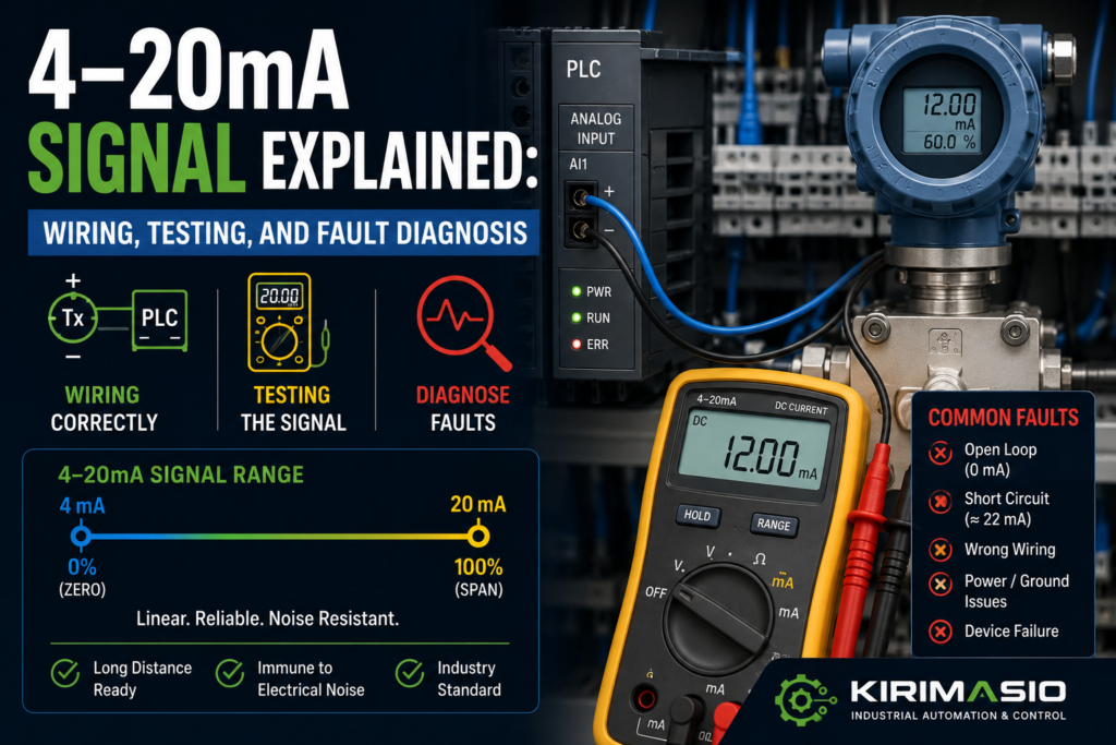
A 4–20mA signal is an analog current signal used to represent a measured value.
The basic idea:
- 4mA = minimum value
- 20mA = maximum value
- 12mA = about 50%
- Below 4mA = possible fault, broken wire, or under-range
- Above 20mA = possible over-range or fault
Example:
A pressure transmitter is scaled from 0 to 10 bar.
- 4mA = 0 bar
- 12mA = 5 bar
- 20mA = 10 bar
Another example:
A level transmitter is scaled from 0 to 100%.
- 4mA = 0%
- 12mA = 50%
- 20mA = 100%
That 4mA starting point is important. It is called a live zero.
With a 0–10V signal, 0V can mean “real zero” or “wire broken.” With 4–20mA, a broken loop usually drops toward 0mA, so the PLC can detect that something is wrong.
That is one reason current loops are so popular in industry.
They don’t just send a value. They can also give a clue when the signal has died.
Why Use 4–20mA Instead of 0–10V?
Voltage signals are useful, but they can be more sensitive to cable length, voltage drop, and electrical noise.
A 4–20mA loop sends a controlled current through the circuit. The transmitter adjusts the current, and the PLC analog input measures it.
Benefits of 4–20mA:
- Works well over long cable runs
- Less affected by voltage drop
- Better noise immunity than many voltage signals
- Broken wire can be detected
- Common in process instrumentation
- Easy to scale in PLCs
- Many transmitters are designed for it
- Can power 2-wire transmitters through the same loop
It is not magic, obviously. Bad wiring, bad shielding, wrong input type, overloaded loop, missing power, or wrong scaling can still ruin the day.
But as analog signals go, 4–20mA is a dependable old workhorse.
Not fancy.
Very useful.
Common Devices That Use 4–20mA
You will often see 4–20mA signals from:
- Pressure transmitters
- Level transmitters
- Flow meters
- Temperature transmitters
- Differential pressure sensors
- Humidity transmitters
- pH transmitters
- Load cell amplifiers
- Valve positioners
- Actuator feedback modules
- Speed reference converters
- Process controllers
- Signal isolators
- Analog output modules
A PLC can also send a 4–20mA analog output to:
- VFDs
- Proportional valves
- Control valves
- Signal converters
- Recorders
- Controllers
- Actuators
So the signal can be either an input to the PLC or an output from the PLC.
That changes how you test it.
2-Wire, 3-Wire, and 4-Wire 4–20mA Devices
Before measuring anything, identify the wiring type.
This is where many faults begin.
2-Wire Transmitter
A 2-wire transmitter uses the same two wires for power and signal.
Typical loop:
+24V → transmitter + → transmitter – → PLC analog input → 0V
The transmitter controls the current flowing in the loop.
This is common for pressure and process transmitters.
3-Wire Transmitter
A 3-wire transmitter usually has:
- +24V supply
- 0V/common
- Signal output
The signal output sends 4–20mA to the PLC input.
4-Wire Transmitter
A 4-wire device has separate power and signal wiring.
Usually:
- Two wires for supply power
- Two wires for analog output loop
This is common for some powered instruments, analyzers, and controllers.
The mistake?
Wiring all of them the same way.
A 2-wire loop is not wired like a 3-wire sensor. If you mix them up, the transmitter may power on incorrectly, the PLC may read zero, or the loop may never complete.
Tiny wiring difference. Big headache.
Basic 4–20mA Loop Wiring
A simple 2-wire current loop looks like this:
+24V DC
  |
  |
Transmitter +
Transmitter -
  |
  |
PLC analog input +
PLC analog input -
  |
  |
0V DC
Current must flow through the whole loop.
If the loop is open anywhere, current stops.
That means:
- Broken wire = no current
- Blown fuse = no current
- Wrong terminal = no current
- Missing 24V = no current
- Wrong input wiring = no current
A 4–20mA loop needs a complete path.
That sounds obvious, but it is the first thing to remember.
No complete loop, no signal.
Common Symptoms of 4–20mA Signal Problems
A bad 4–20mA signal may show up as:
- PLC value stuck at 0
- PLC raw value stuck at minimum
- HMI value stuck at maximum
- Analog input fault
- Signal reads around 0mA
- Signal reads below 4mA
- Signal reads above 20mA
- Value jumps or drifts
- Reading changes when motor starts
- Correct mA at transmitter but wrong PLC value
- Transmitter display value does not match HMI
- Loop works until another device is connected
- Value is inverted
- New transmitter reads wrong range
- 2-wire transmitter does not power up
- PLC module shows overflow/underflow
Don’t panic at the symptom.
Measure the loop.
Current loops are very testable once you know where to put the meter.
Safety Before Testing 4–20mA Signals
A 4–20mA loop is low current, but the panel may contain dangerous voltages.
Before testing:
- Use a proper multimeter
- Set the meter to the correct current range
- Move the meter lead to the current input socket
- Do not place the meter in current mode across 24V supply
- Do not short analog terminals
- Follow lockout/tagout rules when required
- Check the wiring diagram
- Be careful around mains and motor circuits
That meter lead warning matters.
To measure current, most meters require moving the red lead to the mA/A socket. If you forget and then measure voltage, or if you put a current meter directly across a power supply, you can blow the meter fuse.
Or worse, make sparks.
Not ideal. Not professional. Very human, though.
1. Check the Transmitter Power
Start with power.
A transmitter cannot output a signal if it is not powered correctly.
Check:
- 24V DC supply
- Loop fuse
- Electronic circuit breaker
- Transmitter terminals
- Polarity
- Loose wiring
- Field junction box
- Cable damage
- Power supply capacity
For a 2-wire transmitter, power is part of the loop. You may not simply measure +24V and 0V directly at the transmitter like a normal 3-wire device, because the transmitter sits in series with the PLC input.
Good signs:
- Correct loop voltage available
- Transmitter display powers up, if it has one
- Loop current is between 4 and 20mA during normal operation
- PLC analog input receives current
Bad signs:
- Transmitter display off
- 0mA loop current
- No 24V supply
- Blown fuse
- Reverse polarity
- Loose field terminal
- Loop voltage too low
- Transmitter repeatedly resets
If the transmitter has a display and it is off, don’t go straight to PLC scaling.
Find power first.
A dead transmitter has no opinion about scaling.
2. Measure Loop Current Correctly
To measure 4–20mA current, the meter must be placed in series with the loop.
That means you open the loop at one point and insert the meter so current flows through it.
For example:
Loop wire disconnected → meter mA input → meter COM → circuit continuesDo not measure current by placing the meter across two terminals like voltage.
That can short the loop and blow a fuse.
Common places to measure current:
- At PLC analog input terminal
- At transmitter terminal
- At loop test terminals, if installed
- At a terminal block where the loop can be opened safely
- Using a loop calibrator or mA clamp meter, if available
Good readings:
- Around 4mA at minimum process value
- Around 20mA at maximum process value
- Around 12mA at half range
- Stable value when process is stable
Bad readings:
- 0mA
- Less than 4mA during normal process
- More than 20mA
- Unstable or jumping current
- Current changes at transmitter but not at PLC
- Current disappears when connected to input
A mA clamp meter can measure loop current without opening the circuit, which is nice. But not everyone has one.
A normal multimeter works too, if used correctly.
Carefully.
3. Understand What Different mA Values Mean
A 4–20mA signal carries both measurement and diagnostic clues.
Typical interpretation:
| Current | Meaning |
|---|---|
| 0mA | Open loop, no power, broken wire, blown fuse, disconnected transmitter |
| Below 4mA | Under-range, fault signal, wiring issue, transmitter fault, depending on device |
| 4mA | Minimum process value |
| 12mA | Mid-range process value |
| 20mA | Maximum process value |
| Above 20mA | Over-range or fault signal, depending on transmitter setup |
| Around 21–22mA | Often fault/high alarm output on some transmitters |
| Around 3.6mA | Often fault/low alarm output on some transmitters |
Important: exact fault current values depend on the transmitter and configuration.
Some devices output 3.6mA on fault. Some output 21mA. Some can be configured either way.
So don’t assume. Check the manual or device settings.
But as a general troubleshooting clue:
- 0mA usually means loop is open or dead
- 4–20mA usually means the loop is alive
- Outside 4–20mA means fault, under-range, over-range, or bad setup
That already narrows things down.
4. Check the PLC Analog Input Configuration
PLC analog input modules must be configured for the correct signal type.
Check:
- Input channel enabled
- 4–20mA mode selected
- Correct terminals used
- Current input jumper or DIP switch, if required
- Hardware configuration
- Module diagnostics
- Input range
- Filter setting
- Raw value range
- Scaling block
Many analog modules support both voltage and current.
If the channel is configured for 0–10V but wired for 4–20mA, the reading will be wrong or dead.
Good signs:
- Channel set to 4–20mA
- Wiring matches current input terminals
- Module diagnostics OK
- Raw value changes with loop current
Bad signs:
- Channel set to voltage input
- Wire connected to wrong terminal
- Current input resistor missing or wrong, on some systems
- DIP switch wrong
- Channel disabled
- Module shows underflow/overflow
- Raw value stuck
This is very common after module replacement.
The new module is installed, wires are connected, but the channel configuration is still wrong.
The signal is there.
The PLC is not listening correctly.
5. Check PLC Raw Value Before Scaling
Do not trust the HMI first.
Check the raw analog value in the PLC.
Different PLCs use different raw ranges. Common examples include:
- 0 to 27648
- 0 to 32767
- 0 to 4095
- 0 to 10000
- 5530 to 27648 for 4–20mA on some systems
Always check the analog module manual.
The important question is:
Does the raw value change when the loop current changes?
Good signs:
- Raw value changes smoothly
- Raw value matches expected current
- Raw value is stable
- No diagnostic fault
Bad signs:
- Raw value stuck at zero
- Raw value stuck at maximum
- Raw value shows underflow
- Raw value shows overflow
- Raw value jumps randomly
- Raw value correct but HMI value wrong
If the raw value is correct but the displayed engineering value is wrong, the fault is probably scaling.
If the raw value is wrong, check wiring, current, input configuration, and the transmitter.
Raw first.
Pretty HMI numbers later.
6. Check Scaling
Scaling converts the 4–20mA signal into engineering units.
Example:
Pressure transmitter range: 0–10 bar
- 4mA = 0 bar
- 20mA = 10 bar
- 12mA = 5 bar
Common scaling mistakes:
- Scaling 0–20mA instead of 4–20mA
- Wrong transmitter range
- New sensor has different range
- Wrong raw minimum
- Wrong raw maximum
- Decimal point wrong
- HMI also scales an already scaled value
- PLC and HMI scaling both active
- Inverted scaling
- Engineering units copied from another machine
- Bar vs psi confusion
Good signs:
- 4mA shows minimum engineering value
- 20mA shows maximum engineering value
- 12mA shows midpoint
- HMI matches known process value
Bad signs:
- 4mA does not show zero/minimum
- 12mA does not show half range
- HMI value wrong but raw value correct
- Value offset by fixed amount
- Value wrong by fixed ratio
- HMI shows 100% at 12mA
Scaling is where many “bad sensor” problems are born.
Especially after replacing a transmitter with a different range.
Old transmitter: 0–10 bar
New transmitter: 0–16 bar
Both output 4–20mA.
But they do not mean the same thing.
7. Use a Loop Calibrator or Signal Generator
A loop calibrator is one of the best tools for 4–20mA troubleshooting.
It can:
- Simulate a transmitter
- Source 4–20mA into a PLC input
- Measure loop current
- Power some transmitter loops
- Step through values like 4mA, 12mA, 20mA
Useful test:
Disconnect the transmitter and inject known current into the PLC input.
Test points:
- 4mA
- 12mA
- 20mA
Then check what the PLC and HMI display.
Expected example for 0–10 bar:
- 4mA = 0 bar
- 12mA = 5 bar
- 20mA = 10 bar
If the PLC/HMI displays correctly with injected current, the PLC input and scaling are probably okay. The problem is likely field wiring, transmitter, power, or process setup.
If the PLC/HMI displays wrong values with injected current, check PLC configuration and scaling.
This is a clean test.
Much cleaner than arguing with the sensor.
8. Check for Open Loop
An open loop is one of the most common 4–20mA faults.
Open loop means current cannot flow.
Possible causes:
- Broken wire
- Loose terminal
- Blown fuse
- Disconnected transmitter
- Wrong terminal
- Bad junction box connection
- Cable damage
- Incorrect wiring after maintenance
- PLC analog input disconnected
- Transmitter polarity reversed
Symptoms:
- 0mA loop current
- PLC input under-range
- HMI shows minimum or fault
- Transmitter display off, on 2-wire devices
- Analog module fault LED
- No change when process changes
Good signs:
- Loop current flows
- All terminals tight
- Cable continuity good
- Fuse OK
Bad signs:
- 0mA
- Broken conductor
- Loose terminal
- No voltage available to loop
- Field cable damaged
- Transmitter not powered
To find the open point, follow the loop with the drawing.
Power supply → fuse → transmitter → signal wire → PLC input → common/return.
The open point is somewhere in that chain.
Don’t jump around randomly.
Follow the current path.
9. Check Loop Voltage and Burden Resistance
A 4–20mA loop needs enough voltage to push current through the transmitter, wires, input resistance, and any other devices in the loop.
Every input or device in the loop adds resistance, often called burden.
If the loop voltage is too low or burden too high, the transmitter may not be able to drive 20mA.
Symptoms:
- Signal works at low values but cannot reach 20mA
- Transmitter output saturates
- Reading is correct at 4mA but wrong at high range
- Loop current limited below expected value
- Transmitter fault due to low supply
- Signal drops when extra device is connected
Common causes:
- Too many devices in series
- Long cable run
- Input resistance too high
- Low 24V supply
- Bad terminals
- Signal isolator burden
- Wrong wiring through multiple modules
Good signs:
- Enough loop supply voltage
- Current can reach full 20mA
- Voltage at transmitter remains within required range
- Burden within transmitter rating
Bad signs:
- Loop cannot reach 20mA
- Voltage at transmitter too low
- Multiple receivers wired in series incorrectly
- Signal collapses under load
- 24V supply weak
This one is less common than a broken wire, but it matters.
Especially with long loops and multiple devices.
The transmitter is not weak. It may simply not have enough voltage headroom to drive the loop.
10. Check Polarity
Many 4–20mA transmitters and PLC inputs are polarity-sensitive.
Reverse polarity can stop the loop completely.
Check:
- Transmitter + and –
- PLC AI+ and AI-
- 24V supply polarity
- Terminal numbers
- Cable colors
- Junction box wiring
- Shield not used as signal return by mistake
Good signs:
- Polarity matches drawing
- Transmitter powers up
- Current flows correctly
- PLC input reads signal
Bad signs:
- 0mA after replacement
- Transmitter display off
- Signal only works when wires swapped
- PLC input fault
- Reverse wiring in junction box
This happens a lot after replacing a transmitter.
The old cable colors are assumed.
The new device pinout is different.
And suddenly a two-wire loop becomes a small philosophical problem.
Use the datasheet.
Not memory.
11. Check for Wrong Input Type: Voltage vs Current
A 4–20mA signal must go into a current input.
If wired into a 0–10V voltage input, the result may be wrong or useless.
Some analog modules use different terminals for voltage and current. Others use jumpers or software configuration.
Check:
- Correct analog input terminal
- Current mode selected
- Voltage/current DIP switch
- Internal shunt resistor
- Module manual
- PLC hardware config
Good signs:
- Current loop wired to current input
- Channel configured for 4–20mA
- Raw value changes correctly
Bad signs:
- 4–20mA wired to voltage input
- 0–10V mode selected
- Current shunt missing
- Wrong terminal used
- Raw value stuck or strange
Do not assume “analog input” means all analog signals work the same way.
Voltage input and current input are different.
Close cousins, not twins.
12. Check for Noise and Grounding Problems
4–20mA is generally more noise-resistant than 0–10V, but noise can still cause problems.
Especially with bad wiring.
Check:
- Shielded cable
- Shield termination
- Cable route
- VFD motor cables nearby
- Servo cables nearby
- Welding equipment nearby
- Proper grounding
- Signal isolator use
- Ground loops
- Loose 0V/reference terminals
Symptoms of noise:
- Value jumps when motors start
- Reading unstable
- Random spikes
- HMI value flickers
- Fault appears during contactor switching
- Signal changes with VFD speed
- Stable with machine idle, unstable when running
Good signs:
- Stable current
- Shielded cable used
- Cable separated from power wiring
- Grounding follows panel standard
Bad signs:
- Analog cable tied to motor cable
- Shield cut off
- Shield grounded badly
- Value jumps during VFD operation
- Long unshielded run
- Ground loop through multiple devices
If the value is stable when the machine is idle and noisy only during operation, look at noise and grounding.
Don’t blame the transmitter first.
It may be shouting clearly while the wiring picks up factory nonsense.
13. Check Signal Isolators and Barriers
Some loops use extra devices:
- Signal isolators
- Intrinsic safety barriers
- Surge protectors
- Splitters
- Loop-powered displays
- Signal conditioners
- Terminal blocks with test sockets
These devices can fail or be wired incorrectly.
Check:
- Power to isolator
- Input side current
- Output side current
- Correct polarity
- Correct range
- DIP switch settings
- Barrier resistance
- Fault LEDs
- Isolation wiring
- Configuration
Good signs:
- Input current matches output current
- Isolator powered
- No fault LEDs
- Range set to 4–20mA
Bad signs:
- Current present before isolator but not after
- Isolator not powered
- Wrong DIP settings
- Output stuck
- Barrier open
- Signal clipped
- Fault LED active
When a loop has an isolator, test both sides.
Do not assume current going into the isolator means current is coming out.
The signal may enter healthy and leave dead.
Like a tiny analog black hole.
14. Check Multiple Devices on One Loop
Sometimes one 4–20mA signal is sent to more than one device.
For example:
- PLC input
- Local display
- Recorder
- Controller
This must be done correctly.
Some devices can be wired in series in a current loop, but burden voltage must be considered. Other times you need a signal splitter.
Problems happen when devices are added casually.
Symptoms:
- Signal worked before extra display was added
- Loop cannot reach 20mA
- PLC reading changed after recorder installation
- One device reads correctly, another does not
- Transmitter faults with low loop voltage
Good signs:
- Devices wired according to design
- Loop burden within limit
- All readings match
- Splitter/isolator used where needed
Bad signs:
- Devices added without checking burden
- Parallel wiring of current loop inputs
- Signal drops after new device added
- One input drags loop down
- Loop voltage too low
A current loop is not the same as a voltage signal.
You cannot always just connect another input in parallel and expect it to behave.
Analog wiring has rules.
Very boring rules, but still rules.
15. Check Transmitter Range and Configuration
Smart transmitters and configurable instruments may have adjustable ranges.
Check:
- Lower range value
- Upper range value
- Units
- Output mode
- Fault current setting
- Damping/filter setting
- Linear/square root output
- Sensor trim/calibration
- Loop test mode
- Fixed output mode
A transmitter may be configured for a different range than expected.
Example:
The PLC expects:
4–20mA = 0–10 barBut the transmitter is configured:
4–20mA = 0–25 barThe current output is correct for the transmitter configuration, but the PLC scaling is wrong for that range.
Good signs:
- Transmitter range matches PLC scaling
- Units match
- Output mode correct
- No fixed output test mode active
Bad signs:
- New transmitter has factory range
- Output locked at fixed mA for testing
- Square-root output enabled unexpectedly
- Wrong units
- Fault current configured differently than expected
Smart devices can be too smart for their own good.
Always check the configuration after replacement.
16. Check If the Transmitter Is in Fault Mode
Some transmitters output a defined fault current when they detect an internal problem or sensor failure.
This may be:
- Around 3.6mA
- Around 21mA
- Another configured value
Possible causes:
- Sensor element failure
- Over-range
- Under-range
- Internal electronics fault
- Bad process connection
- Temperature sensor broken
- Pressure port blocked
- Configuration error
- Device diagnostic alarm
Check:
- Transmitter display
- Diagnostic LEDs
- HART/field communicator diagnostics, if applicable
- Device manual
- Fault current setting
- Process condition
Good signs:
- Transmitter healthy
- Output current represents process
- No diagnostic alarm
Bad signs:
- Output stuck at fault current
- Device display shows error
- Sensor diagnostic fault
- Output below 4mA or above 20mA with alarm
- Process value out of measuring range
A 21mA reading is not always “maximum process.”
It may be a fault signal.
Check the transmitter configuration.
17. Check PLC Alarm Limits
PLC programs often use analog signal limits for fault detection.
For example:
- Below 3.8mA = wire break
- Above 20.5mA = over-range
- Below 4mA = under-range
- Above 21mA = transmitter fault
If these limits are wrong, the PLC may generate false alarms.
Check:
- Low fault threshold
- High fault threshold
- Alarm delay timer
- Scaling before/after alarm check
- Raw vs scaled comparison
- Sensor expected range
- Transmitter fault current
Good signs:
- Alarm limits match transmitter behavior
- Short noise spikes filtered with delay
- Fault alarm appears only when signal is truly abnormal
Bad signs:
- Alarm threshold too tight
- Normal signal triggers under-range
- Fault current interpreted as valid process
- No alarm on 0mA
- PLC checks scaled value incorrectly
Fault diagnosis is not only about the wire.
Sometimes the signal is fine, but the PLC fault logic is badly set.
A perfectly healthy 3.9mA during slight under-range may become an alarm storm if the PLC threshold is too aggressive.
Quick Checklist: 4–20mA Signal Troubleshooting
Use this order.
- Identify the device
- 2-wire, 3-wire, or 4-wire?
- Input or output?
- Transmitter range?
- Check power
- 24V supply present?
- Fuse OK?
- Transmitter display on?
- Correct polarity?
- Measure loop current
- Meter in series
- Around 4–20mA during normal operation
- 0mA means open/dead loop
- Check PLC input configuration
- Channel set to 4–20mA
- Correct terminals
- DIP switches/jumpers correct
- Channel enabled
- Check raw PLC value
- Does raw value change with current?
- Any underflow/overflow?
- Module diagnostic fault?
- Check scaling
- 4mA = engineering minimum
- 20mA = engineering maximum
- 12mA = midpoint
- Correct transmitter range?
- Check wiring
- Loose terminals
- Broken loop
- Wrong polarity
- Field junction box
- Cable damage
- Check loop voltage/burden
- Enough supply voltage?
- Too many devices in loop?
- Loop can reach 20mA?
- Check noise
- Shielded cable
- Proper grounding
- Away from VFD/motor cables
- Check extra devices
- Isolators
- Barriers
- Displays
- Splitters
- Surge protectors
- Check transmitter configuration
- Range
- Units
- Fault current
- Damping
- Output mode
- Check PLC alarm logic
- Wire-break threshold
- High fault threshold
- Alarm delay
- Fault current interpretation
Good vs Bad Signs
| Check Area | Good Sign | Bad Sign |
| Loop current | Stable 4–20mA | 0mA, below 4mA, above 20mA unexpectedly |
| Transmitter power | Display on, polarity correct | Display off, blown fuse, no loop voltage |
| PLC input setup | Channel set to 4–20mA | Set to 0–10V or disabled |
| Raw PLC value | Changes with loop current | Stuck, overflow, underflow |
| Scaling | 4mA=min, 20mA=max | Wrong range, offset, double scaling |
| Wiring | Complete loop, tight terminals | Open loop, loose wire, reversed polarity |
| Loop burden | Current reaches full range | Cannot reach 20mA, voltage too low |
| Noise | Stable signal during operation | Jumps when motors/VFDs run |
| Isolator/barrier | Input and output both healthy | Signal present before, missing after |
| Transmitter config | Range matches PLC | Wrong range, fault current, fixed output |
| Alarm logic | Fault thresholds sensible | False alarms or no wire-break alarm |
Example 1: PLC Reads 0, Transmitter Display Is Off
A pressure transmitter should show tank pressure on the HMI.
HMI reads 0 bar.
The transmitter display is off.
You measure loop current: 0mA.
Then you check the loop fuse and find it blown.
Cause: transmitter loop has no power.
Not PLC scaling. Not transmitter range. Not HMI tag.
Power first.
Always power first.
Example 2: Loop Current Is 12mA, HMI Shows 80%
A pressure transmitter output measures 12mA.
The range should be 0–10 bar, so 12mA should show around 5 bar.
But the HMI shows 8 bar.
You check the raw PLC value. It is correct for 12mA.
Then you check scaling and find the HMI is scaling the already-scaled PLC value again.
Cause: double scaling.
The loop is good.
The math is bad.
Example 3: New Transmitter Reads Wrong
A level transmitter was replaced.
The loop current changes normally. PLC input works. Wiring is good.
But the displayed level is wrong.
Old transmitter:
4–20mA = 0–2 metersNew transmitter:
4–20mA = 0–5 metersCause: replacement transmitter has different range.
The signal is healthy, but the PLC scaling no longer matches the transmitter.
Same current.
Different meaning.
This one catches people all the time.
Example 4: Signal Jumps When VFD Starts
A flow reading is stable while the machine is idle.
When a VFD starts, the PLC value jumps around.
You inspect the wiring and find the analog cable routed together with VFD motor output cables.
Cause: electrical noise or grounding issue affecting the loop.
Fix:
- Separate analog cable from motor/VFD cables
- Use proper shielded cable
- Check shield termination
- Check grounding
- Add isolator/filter if required
Current loops are good.
They are not invincible.
Example 5: Current Present Before Isolator, Missing After
A transmitter loop measures 14mA before a signal isolator.
PLC reads 0.
You measure the isolator output side: 0mA.
The isolator has no power.
Cause: signal isolator output is dead because the isolator power supply is missing.
The transmitter was working.
The signal died in the middle.
Always check both sides of signal conditioners.
Common Mistakes When Troubleshooting 4–20mA Signals
The first mistake is measuring current like voltage.
Current must be measured in series.
The second mistake is forgetting to move the multimeter lead to the mA socket.
A tiny detail. A blown meter fuse.
The third mistake is assuming 0mA means minimum value.
In a 4–20mA loop, 4mA is usually minimum. 0mA usually means fault or open loop.
The fourth mistake is wiring a 2-wire transmitter like a 3-wire sensor.
Very common. Very frustrating.
The fifth mistake is configuring the PLC input for 0–10V instead of 4–20mA.
Same analog module, wrong mode.
The sixth mistake is blaming the transmitter when scaling is wrong.
If mA and raw value are correct, check the math.
The seventh mistake is ignoring loop burden.
If the loop cannot reach 20mA, check voltage and total resistance.
The eighth mistake is adding displays or extra devices to the loop without checking whether the loop can drive them.
Analog loops do not enjoy random passengers.
Tools for 4–20mA Troubleshooting
Useful tools:
- Digital multimeter with mA range
- Loop calibrator
- mA clamp meter
- PLC programming software
- Electrical schematic
- Transmitter datasheet
- Analog module manual
- HART communicator, for smart transmitters
- Signal isolator manual
- Spare fuse
- Known-good transmitter or simulator
- Screwdriver and terminal markers
- Shielded cable tester, if needed
A loop calibrator is the best friend here.
Inject 4mA, 12mA, and 20mA into the PLC input and check the HMI.
That test quickly separates PLC/scaling problems from field transmitter problems.
Clean. Fast. Very satisfying.
Final Thoughts
A 4–20mA signal is simple once you think of it as a loop.
Current must leave the power source, pass through the transmitter, pass through the analog input, and return through the circuit. If the loop opens anywhere, the signal dies.
When troubleshooting, follow this path:
Power → transmitter → loop current → PLC input → raw value → scaling → HMI value.
If current is 0mA, look for open loop, missing power, blown fuse, broken wire, or wrong polarity.
If current is between 4 and 20mA but the PLC value is wrong, check input configuration and scaling.
If current is unstable, check noise, grounding, shielding, loose wires, and transmitter configuration.
If current is outside the normal range, check whether the transmitter is reporting a fault or process over-range.
And remember: 4mA is not zero current. It is the minimum live signal.
That little idea is the heart of the whole system.
Once you understand that, 4–20mA troubleshooting becomes much less mysterious.