A safety relay that refuses to reset can make a machine feel completely locked up.
The emergency stop is released. Guards are closed. The operator presses reset. Nothing.
No output click. No safety OK signal. No machine ready. Just a few LEDs on the safety relay, sitting there like they know exactly what is wrong but refuse to explain it in normal language.
And then someone usually says:
“Maybe the safety relay is bad.”
Maybe.
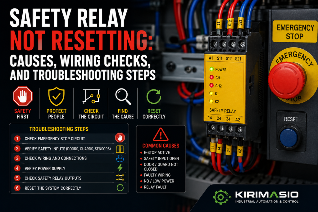
But most of the time, the safety relay is doing its job. It is not resetting because one required condition is missing. One E-stop channel is open. A guard switch is misaligned. The reset button is wired wrong. The feedback loop is open. A contactor auxiliary contact is stuck. The 24V supply is missing. Or the relay is set for manual reset but nobody wired the reset circuit properly.
Safety relays are strict. Annoyingly strict sometimes.
But that is the point.
They are designed to prevent dangerous restart when the safety circuit is not proven healthy.
So don’t bypass it. Don’t guess. Follow the safety circuit step by step.
What Does a Safety Relay Actually Do?
A safety relay monitors safety devices and switches safety outputs only when conditions are correct.
It may monitor:
- Emergency stop buttons
- Guard door switches
- Safety gate locks
- Light curtains
- Safety scanners
- Two-hand controls
- Safety mats
- Rope pull switches
- Safety contactors
- External device feedback
When everything is healthy, the safety relay closes its safety outputs. Those outputs may enable contactors, drives, solenoids, PLC safety inputs, or drive STO inputs.
When something unsafe happens, the safety relay opens its outputs.
Simple idea.
But inside the circuit, it checks more than just “is the button released?”
It may also check:
- Both safety channels
- Timing between channels
- Reset input
- Feedback loop
- Cross-faults
- External contactor state
- Correct wiring
- Internal fault condition
That is why a safety relay may refuse to reset even when the machine looks safe from the outside.
The relay needs proof.
Not vibes.
Common Symptoms When a Safety Relay Will Not Reset
A non-resetting safety relay can show up in several ways:
- Safety relay output LED stays off
- Reset button does nothing
- One input channel LED is off
- Safety relay clicks, then drops out
- Safety relay power LED is off
- Fault LED is on
- Machine reset button works sometimes
- Safety relay resets only when one guard is pushed hard
- HMI shows “safety circuit not ready”
- Safety relay resets, but PLC still does not see safety OK
- Drive STO remains active
- Contactor feedback fault blocks reset
- Safety relay resets after power cycle, then fails again
Do not treat all of these as the same fault.
If the relay has no power, start with 24V supply.
If one channel is missing, trace the E-stop or guard circuit.
If both channels are healthy but reset does nothing, check reset wiring and reset mode.
If it resets then drops, check feedback/EDM, contactors, unstable inputs, or 24V dips.
The LEDs usually tell you where to start.
They are not always friendly, but they are useful.
Safety Warning: Do Not Bypass the Relay
This part matters.
A safety relay is part of the machine safety system. Do not bridge safety outputs, bypass E-stops, tape guard switches, or force contactors just to “test quickly.”
That quick test can put someone in danger.
Before troubleshooting:
- Follow lockout/tagout rules
- Use the electrical schematic
- Understand the machine movement risk
- Use a proper multimeter
- Keep people clear of moving parts
- Do not bypass safety devices
- Do not change safety wiring without proper approval
- Verify the safety function after repair
A machine that runs with a bypassed safety relay is not repaired.
It is unsafe.
And unsafe machines do not care how busy production is.
1. Check Safety Relay Power Supply
Start with power.
A safety relay cannot reset if it is not powered.
Many safety relays use 24V DC on terminals often marked something like A1 and A2, but terminal names vary by manufacturer. Always check the relay diagram.
Check:
- 24V DC at relay supply terminals
- 0V/common connection
- Control fuse or electronic breaker
- Loose terminals
- Power LED
- Power supply load
- Voltage drop when reset is pressed
- Correct relay supply voltage
Good signs:
- Power LED is on
- Correct voltage at supply terminals
- Voltage remains stable
- No flickering LEDs
Bad signs:
- No power LED
- 0V or low voltage
- Power LED flickers
- Relay clicks repeatedly
- Fuse blown
- 24V supply drops when outputs energize
- Wrong supply voltage
Measure between the relay supply terminals, not just from +24V to cabinet ground.
The relay needs proper voltage across its own supply.
If the safety relay power is unstable, fix that first. No safety logic works properly with a dying 24V supply.
2. Check the Emergency Stop Circuit
Emergency stops are one of the first things to check.
Not just the obvious front-panel button. All of them.
Machines may have E-stops on:
- Main operator panel
- Rear side of machine
- Conveyor section
- Robot cell
- Maintenance station
- Pendant
- Remote HMI
- Feeder section
- Palletizer
- Safety rope switch
One pressed E-stop anywhere can block reset.
Check each E-stop physically:
- Is it fully released?
- Does it twist or pull back correctly?
- Is the contact block attached?
- Are both channels closed when released?
- Are wires tight?
- Is the button damaged?
Good signs:
- All E-stops released
- Both safety channels closed
- Safety relay input LEDs healthy
- HMI no longer shows E-stop active
Bad signs:
- One E-stop still pressed
- Button released but contact still open
- Broken contact block
- Loose wire
- One channel missing
- E-stop feels jammed or damaged
A button can look released from the front while the contact block behind it stays open.
The panel face tells one story.
The wiring tells another.
Trust the wiring.
3. Check Both Safety Channels
Most safety relay circuits use two channels.
For example, an emergency stop may have two normally closed contacts. The safety relay monitors both.
If one channel is healthy and the other is open, the relay will not reset.
Check:
- Channel 1 input
- Channel 2 input
- Dual-channel wiring
- E-stop contacts
- Guard switch contacts
- Terminal numbers
- Cross-wiring
- Shorts between channels
- Correct NC contacts used
Good signs:
- Both channels open when safety device is activated
- Both channels close when safety device is released
- Safety relay shows both inputs healthy
- No fault LED
Bad signs:
- Only one channel LED on
- One channel permanently open
- One channel permanently closed
- Channel mismatch fault
- Wrong contact type used
- Broken wire on one channel
- Channels shorted together
This is a common mistake after replacing an E-stop or guard switch.
Someone wires one channel correctly and the other one wrong.
From a distance, everything looks fine.
The relay disagrees.
And the relay wins.
4. Check Guard Door Safety Switches
A safety relay may not reset because a guard door is not detected as closed.
Check:
- Mechanical tongue switches
- Magnetic safety switches
- RFID coded switches
- Door interlocks
- Guard locks
- Hinged safety switches
- Access panel switches
- Loose brackets
- Bent actuators
- Cable connectors
A guard can look closed but still not make the switch.
Common causes:
- Door not fully closed
- Switch misaligned
- Actuator bent
- Mounting screws loose
- Door hinge dropped
- Guard lock not engaged
- Wrong actuator after replacement
- Connector loose
- Safety switch damaged
Good signs:
- Switch LED indicates closed/locked
- Safety relay channels become healthy
- HMI shows guard closed
- No flicker when door is moved gently
Bad signs:
- Door closed but input missing
- Switch LED red/flashing
- Guard must be pushed hard to reset
- Signal flickers when machine vibrates
- Door lock does not engage
- Actuator not entering switch properly
A guard switch can be 2 mm out of position and stop the whole machine.
Tiny misalignment.
Huge downtime.
Very industrial.
5. Check Light Curtains and Safety Scanners
If the safety relay monitors light curtains or scanners, make sure the protected area is clear.
Check:
- Light curtain transmitter power
- Receiver power
- Alignment
- Dirty lens
- Blocked beam
- Reflective surfaces
- Safety scanner zone
- Scanner lens
- Muting sensors
- OSSD outputs
- Cable connectors
- Fault LEDs
Light curtains often use OSSD outputs. These outputs must be connected correctly to the safety relay input or safety controller.
Good signs:
- Light curtain shows green/clear
- OSSD outputs active
- Scanner field clear
- No fault LED
- Safety relay input channels healthy
Bad signs:
- Beam blocked
- Lens dirty
- Receiver misaligned
- OSSD fault
- Muting fault
- Scanner zone blocked
- One OSSD channel missing
- Fault appears after cleaning or adjustment
Do not assume the light curtain is clear because nobody is standing in it.
A bracket, cable tie, tool, product piece, pallet edge, or dust buildup can block it.
Machines are very good at finding stupid ways to stop.
6. Check the Reset Button
A safety relay may require a manual reset signal.
The reset button is usually a normally open pushbutton. When pressed, it sends a reset pulse to the relay.
Check:
- Reset button contact
- Voltage before reset button
- Voltage after reset button when pressed
- Reset input terminal on relay
- Loose wires
- Wrong contact block
- Stuck button
- Broken wire
- HMI reset command, if reset is through PLC/HMI
Good signs:
- Reset input changes only when button is pressed
- Relay sees reset signal
- Button springs back correctly
- Wiring matches manual
Bad signs:
- Reset input never changes
- Reset signal permanently on
- Wrong contact type used
- Button mechanically stuck
- Loose terminal
- Contact block fallen off
- No voltage feeding reset circuit
A reset button can click mechanically and still fail electrically.
The click is not a measurement.
Use the meter.
Also, a reset signal that is permanently ON can be a problem. Some safety relays require the reset button to be pressed after the safety inputs are healthy. If reset is already active too early, the relay may refuse to reset.
Safety relays are picky about sequence.
Annoying, yes. Intentional, also yes.
7. Check Manual Reset vs Automatic Reset Wiring
Safety relays can often be wired for different reset modes.
Common modes:
- Manual reset
- Monitored manual reset
- Automatic reset
Manual reset requires a button press.
Monitored manual reset may check that the reset button is released and then pressed properly.
Automatic reset enables outputs as soon as safety inputs are healthy, if the circuit is designed that way.
Check:
- Relay manual
- Reset terminal wiring
- DIP switch settings
- Jumper links
- Configuration software, if programmable
- Machine safety design
- Replacement relay settings
Good signs:
- Reset mode matches the machine design
- Wiring matches relay manual
- Reset works only when safety inputs are healthy
- Replacement relay configured like the old one
Bad signs:
- Wrong reset mode selected
- Missing jumper
- Reset wired to wrong terminal
- DIP switches set differently
- Replacement relay behaves differently
- Relay expects monitored reset but receives permanent signal
Do not change automatic/manual reset just to make the machine run.
Reset behavior is part of the safety design.
Changing it casually is not troubleshooting. It is modifying a safety function.
Different thing.
8. Check the Feedback Loop / EDM Circuit
This is one of the most common reasons a safety relay will not reset.
Many safety relays monitor external devices through a feedback loop. This is often called:
- EDM
- External Device Monitoring
- Feedback loop
- K1/K2 feedback
- Contactor monitoring
- Safety output feedback
The safety relay checks whether the controlled contactors are actually off before it allows reset.
Usually this is done through normally closed auxiliary contacts from contactors K1 and K2.
If a contactor is stuck, welded, or the feedback contact is wired wrong, the safety relay will not reset.
Check:
- K1 auxiliary NC contact
- K2 auxiliary NC contact
- Feedback loop continuity
- EDM terminal wiring
- Contactor mechanical state
- Loose auxiliary contact block
- Wrong NO/NC contact used
- Safety relay EDM LED
- Feedback wire broken
Good signs:
- Feedback loop closed when contactors are off
- Feedback opens when contactors energize
- Safety relay accepts reset
- No EDM fault
Bad signs:
- Feedback loop open before reset
- One contactor stuck closed
- Wrong auxiliary contact installed
- Auxiliary block loose
- Feedback wire broken
- EDM fault LED on
- Safety relay resets then drops
This can confuse people because all E-stops and guards may be healthy.
But the relay still says no.
Why?
Because it cannot prove that the output contactors are in the safe state.
That is exactly what EDM is for.
9. Check Safety Contactors
If the relay controls safety contactors, inspect them.
Check:
- Coil voltage
- Contactor mechanical movement
- Welded main contacts
- Auxiliary feedback contact
- Burn marks
- Overheating
- Loose terminals
- Contactor stuck closed
- Contactors K1 and K2 drop out properly
Good signs:
- Contactors are off before reset
- Auxiliary NC feedback contacts are closed
- Contactors pull in cleanly after reset
- Contactors drop out when safety circuit opens
Bad signs:
- Contactor stuck
- Auxiliary feedback wrong
- Coil damaged
- Contactor welded
- Feedback contact not changing
- Contactors chatter
- Burnt smell
- Discolored terminals
A welded contactor is not a small nuisance.
It is exactly the kind of dangerous fault a safety relay is meant to detect.
If the feedback loop shows a contactor problem, take it seriously.
10. Check Safety Relay Output Wiring
Sometimes the safety relay actually resets, but the machine still says “safety not reset.”
That can happen if the safety relay output is not reaching the PLC, contactor, drive, or STO input.
Check:
- Safety output terminals
- Output LEDs
- Output contact voltage
- Fuses after safety relay
- Expansion relay
- Contactor coil supply
- PLC safety OK input
- Drive STO terminals
- Broken wire after relay
- Terminal jumpers
Good signs:
- Relay output LED turns on
- Safety output contact closes
- Voltage reaches downstream device
- PLC sees safety OK
- Drives show STO satisfied
Bad signs:
- Output LED on but no voltage downstream
- Bad output contact
- Blown fuse after relay
- Broken wire
- Expansion module not switching
- PLC safety input missing
- Drive STO still active
Do not stop at “the safety relay LED is on.”
Follow the output.
The relay may be healthy, but the signal may disappear after it.
11. Check Drive STO Inputs
Modern VFDs and servo drives often use STO, or Safe Torque Off.
A machine may not become ready if a drive STO input is still open, even if the main safety relay has reset.
Check:
- STO channel 1
- STO channel 2
- Safety relay output to STO
- Drive display
- Drive ready signal
- STO fault code
- Wiring to drive terminals
- Reset requirement
- PLC feedback from drive
Good signs:
- Both STO channels active
- Drive shows ready
- No STO fault
- PLC receives drive ready/safety OK
Bad signs:
- One STO channel missing
- Drive shows STO active
- STO fault remains
- Safety relay output reaches one channel but not the other
- Drive ready signal missing
If one drive still shows STO active, the machine may refuse to start even though the safety relay reset looks successful.
The safety chain does not always end at the relay.
Sometimes it continues into every drive.
12. Check for Channel Mismatch or Discrepancy Fault
Safety relays often monitor whether both safety channels change state correctly.
If one channel opens and the other does not, or one closes too late, the relay may detect a discrepancy fault.
Possible causes:
- Worn E-stop contact
- Sticky guard switch
- Loose wire
- Broken contact block
- Mechanical door misalignment
- Wrong switch contact type
- One channel bypassed in the past
- Slow or bouncing contact
- Damaged cable
Good signs:
- Both channels change together
- No discrepancy fault
- Reset accepted
Bad signs:
- One channel LED lags
- One channel flickers
- Relay fault after E-stop cycle
- Reset works sometimes
- Reset works only after cycling power
- One input stays closed when safety device is operated
Watch the input LEDs while operating the safety device.
If one channel changes and the other does not, follow the missing channel.
This is not a mystery. It is the relay pointing at the bad side.
Not politely, but still.
13. Check Cross-Fault Detection Wiring
Some safety relays detect shorts between channels or shorts to supply.
Depending on the relay design, channels may use test pulses or different internal paths to detect wiring faults.
A short between channels can prevent reset.
Check:
- Damaged cable between channels
- Wires crushed together
- Moisture in connector
- Wrong terminal jumpers
- Incorrect wiring after repair
- Safety relay manual wiring diagram
- Cross-fault LED or diagnostic code
Good signs:
- Channels isolated as required
- No shorts between input channels
- Wiring matches relay diagram
- No moisture or damaged insulation
Bad signs:
- Channels shorted together
- Wrong jumper installed
- Cable crushed
- Water inside safety connector
- Relay shows input fault
- Fault appeared after cable repair
Do not randomly jumper safety channels.
Some relays will detect it. More importantly, it may defeat the safety function.
Safety wiring is not normal control wiring.
Treat it with more respect.
14. Check Wiring and Terminals
Loose wiring causes many reset faults.
Check:
- Safety relay terminals
- E-stop terminals
- Guard switch connectors
- Reset button terminals
- Feedback loop terminals
- Contactor auxiliary terminals
- 24V and 0V terminals
- Cabinet door wiring
- Junction boxes
- Cable glands
- M12 connectors
Look for:
- Loose screws
- Broken ferrules
- Pulled wires
- Moisture
- Corrosion
- Oil contamination
- Bent connector pins
- Crushed cable
- Wrong terminal numbers
- Recent wiring changes
Good signs:
- Terminals tight
- Wires match drawing
- Connectors dry and secure
- No damaged insulation
Bad signs:
- Wire pulls out
- Connector loose
- Corroded pins
- Water in junction box
- Cabinet door wire broken
- Cable damaged near hinge or moving part
- Recently replaced device wired differently
Cabinet door wiring is a sneaky one.
Reset buttons and E-stops are often on the door. Years of opening and closing the panel can break conductors inside the insulation.
The fault looks random.
The wire is just tired.
15. Check Recent Changes
Always ask what changed before the fault started.
Safety relay reset problems often appear after:
- E-stop replacement
- Guard switch replacement
- Safety relay replacement
- Contactor replacement
- VFD replacement
- Door adjustment
- Panel rewiring
- Machine cleaning
- Cable repair
- PLC/safety PLC program update
- Light curtain alignment
- New actuator installed
- Maintenance work near guards
A replacement safety relay may have different terminal layout, reset settings, or feedback wiring.
A replacement contactor may have the wrong auxiliary contact.
A replacement guard switch may need alignment or coding.
A replacement light curtain may have different OSSD wiring.
“Same-looking part” does not always mean “same wiring.”
That sentence could save a shift.
Quick Checklist: Safety Relay Not Resetting
Use this order when troubleshooting.
- Check power
- Safety relay supply voltage
- Power LED
- Fuse/electronic breaker
- Stable 24V DC
- Check E-stops
- All released
- Both NC contacts healthy
- No loose contact block
- Check safety channels
- Channel 1 healthy
- Channel 2 healthy
- No mismatch fault
- Check guard switches
- Doors closed
- Switches aligned
- Locks engaged
- Connectors secure
- Check light curtains/scanners
- Beam clear
- OSSD outputs active
- No fault LED
- Check reset button
- Reset signal reaches relay
- Button not stuck
- Correct contact used
- Check reset mode
- Manual/automatic reset wiring correct
- DIP switches or configuration correct
- Check EDM feedback
- Feedback loop closed before reset
- K1/K2 auxiliary contacts correct
- No stuck contactor
- Check safety outputs
- Output LEDs turn on
- Output contacts close
- Voltage reaches downstream devices
- Check drives
- STO channels satisfied
- Drive ready signal active
- No STO fault
- Check wiring
- Loose terminals
- Broken wires
- Wet connectors
- Wrong jumpers
- Check recent changes
- Replaced parts
- Rewired devices
- Adjusted guards
- Changed configuration
Good vs Bad Signs
| Check Area | Good Sign | Bad Sign |
|---|---|---|
| Relay power | Power LED on, stable 24V | No power, low voltage, flickering |
| E-stop circuit | All E-stops released | One button pressed or contact open |
| Safety channels | Both channels healthy | One channel missing, mismatch fault |
| Guard switch | Door closed and detected | Door closed but input missing |
| Light curtain | Clear, OSSD active | Blocked, misaligned, OSSD fault |
| Reset button | Reset input changes when pressed | No reset signal or stuck reset |
| Reset mode | Wiring/config matches design | Wrong jumper, wrong DIP setting |
| EDM feedback | Feedback closed before reset | Open feedback loop, stuck contactor |
| Safety outputs | Outputs close after reset | Output stays off or voltage missing |
| Drive STO | Both channels satisfied | STO active, one channel missing |
| Wiring | Tight, dry, correct | Loose, wet, broken, miswired |
| Replacement parts | Same type/configured correctly | Wrong contact type, wrong settings |
Example 1: One Safety Channel Is Missing
A machine will not reset after an E-stop.
The safety relay power LED is on.
Channel 1 LED is on.
Channel 2 LED is off.
You check the E-stop circuit and find one contact block on the rear emergency stop is not closing after release.
Cause: faulty E-stop contact on channel 2.
The relay is not bad.
It is refusing reset because only half the safety circuit is healthy.
And half a safety circuit is not enough.
Example 2: Reset Button Does Nothing
All guards are closed. Both safety channels are healthy.
You press reset, but the relay output stays off.
You measure the reset input terminal while pressing the button. No voltage change.
Then you check the reset button. The contact block is loose behind the panel.
Cause: reset signal never reaches the safety relay.
The button clicked.
The circuit did not care.
Example 3: Safety Relay Shows EDM Fault
E-stops are released. Guard switches are healthy. Reset button works.
Still no reset.
The relay indicates an EDM or feedback fault.
You check the feedback loop through contactors K1 and K2. One auxiliary NC contact is open even though the contactor is supposed to be off.
Cause: contactor feedback loop open.
Possible reasons: stuck contactor, wrong auxiliary contact, broken feedback wire, or loose auxiliary block.
The safety relay is protecting the machine from restarting because it cannot prove the contactor state.
That is not annoying behavior.
That is correct behavior.
Example 4: Safety Relay Resets Then Drops Immediately
The relay resets, outputs turn on for a moment, then drop.
You watch the guard switch LEDs and see one door switch flicker when contactors pull in and the machine vibrates.
The door actuator is slightly loose.
Cause: unstable guard switch signal during vibration.
The circuit is healthy while idle, but not stable during movement.
Fix the mechanical alignment and verify both channels remain stable.
Example 5: Relay Output On, Machine Still Not Ready
The safety relay output LED is on.
But the HMI still says “Safety not ready.”
You check the PLC safety OK input. It is off.
Then you measure after the safety relay output fuse. No voltage.
The fuse after the relay output is blown.
Cause: safety relay reset is OK, but downstream safety OK signal is not reaching the PLC.
This is why you follow the output all the way.
LEDs help.
Measurements prove.
Common Mistakes When Troubleshooting Safety Relays
The first mistake is replacing the safety relay too early.
Most reset faults are wiring, input, feedback, or safety device problems.
The second mistake is checking only one safety channel.
Dual-channel safety circuits need both channels healthy.
The third mistake is ignoring the reset button wiring.
A mechanical click is not proof of electrical reset.
The fourth mistake is forgetting EDM feedback.
A safety relay may not reset because it cannot prove the contactors are off.
The fifth mistake is confusing “safety relay reset” with “machine ready.”
The relay may be reset, but the PLC or drive may still block operation.
The sixth mistake is changing reset mode without understanding the safety design.
Do not do that casually.
The seventh mistake is bypassing safety devices.
No production target is worth making a dangerous machine.
Tools for Safety Relay Troubleshooting
Useful tools:
- Electrical schematic
- Multimeter
- Safety relay manual
- PLC or safety PLC diagnostics
- Insulated screwdrivers
- Terminal markers
- HMI safety status page
- Drive display for STO status
- Continuity tester
- Spare reset contact block
- Cable tester
- Known-good safety switch connector, if available
The best tool is still a clear method.
Follow the chain:
Safety device → safety relay input channels → reset input → feedback loop → safety outputs → PLC/contactors/drives.
Somewhere in that chain, the condition is missing.
Find that point.
Final Thoughts
When a safety relay is not resetting, do not start by blaming the relay.
Start with the basics.
Check power. Check all emergency stops. Check both safety channels. Check guard switches and light curtains. Check the reset button. Check manual reset wiring. Check EDM feedback. Check contactor auxiliary contacts. Check safety outputs. Check drive STO inputs. Then check recent changes and wiring mistakes.
A safety relay usually refuses to reset for a reason.
Maybe the reason is simple: a pressed E-stop on the back of the machine.
Maybe it is sneaky: one feedback contact stuck open.
Maybe it is mechanical: a guard switch slightly misaligned.
But the troubleshooting method is the same.
Follow the safety chain.
Measure each condition.
And never bypass the protection just to make the machine run.
A safety relay that will not reset is frustrating.
A machine that resets when it should not is much worse.