A PLC looks like it reacts instantly.
You press a button, a light turns on. A sensor sees a part, a cylinder moves. A limit switch changes, the machine stops.
From the outside, it feels immediate.
But inside the PLC, things happen in a very specific rhythm. Over and over. Thousands of times per minute.
That rhythm is called the PLC scan cycle.
And once you understand it, a lot of PLC behavior starts making more sense. Why an input may be missed. Why an output does not turn on until the next scan. Why a timer seems slightly delayed. Why fast encoder signals need special inputs. Why the HMI value may not update at the exact same moment as the PLC logic.
Small topic?
Not really.
The scan cycle is one of those boring-looking PLC basics that quietly affects everything.
What Is a PLC Scan Cycle?
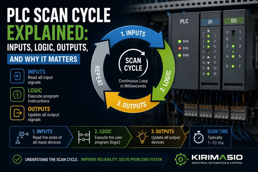
A PLC scan cycle is the repeated process a PLC uses to read inputs, execute the program, update outputs, and handle communication or diagnostics.
In simple form, the scan cycle looks like this:
1. Read inputs
2. Execute program logic
3. Update outputs
4. Handle communication and diagnostics
5. Repeat
Then it starts again.
And again.
And again.
A PLC does not usually “watch everything continuously” in the way beginners imagine. It checks the machine in repeated snapshots.
Very fast snapshots, yes.
But still snapshots.
That detail matters.
Simple Example: Start Button and Motor Output
Imagine a basic motor start circuit in PLC logic.
You have:
- Start button input
- Stop button input
- Motor output
- Motor run latch
The PLC scan may work like this:
Input scan:
PLC reads start button = ON
PLC reads stop button = OK

Logic scan:
PLC sees start command
PLC turns motor run bit ON

Output update:
PLC energizes motor contactor output
Then the next scan begins.
To the operator, it feels instant.
But internally, the PLC first reads the input, then solves the logic, then updates the output.
That order is important.
The Main Parts of a PLC Scan Cycle
Most PLCs follow a similar basic pattern, although exact details depend on the brand and CPU.
The main parts are:
- Input scan
- Program execution
- Output update
- Communication
- Diagnostics and system tasks
Let’s go through each one.
1. Input Scan
During the input scan, the PLC reads the status of its input terminals or input modules.
Inputs may include:
- Pushbuttons
- Selector switches
- Emergency stop status
- Safety relay feedback
- Proximity sensors
- Photoelectric sensors
- Limit switches
- Pressure switches
- Level switches
- Encoder signals, if using high-speed inputs
- Analog signals
- Drive ready signals
- Contactor feedback contacts
The PLC stores the input states in memory.
This memory is sometimes called an input image table, process image input, or simply input memory.
So if input I0.0 is ON during the input scan, the PLC stores it as ON.
Then the program uses that stored value while executing logic.
That means the logic is usually not reading the physical terminal every microsecond. It is reading the input state that was captured at the beginning of the scan.
That sounds like a tiny difference.
Sometimes it is.
Sometimes it explains the whole fault.
2. Program Execution
After reading inputs, the PLC executes the user program.
This may include:
- Ladder logic
- Function block diagram
- Structured text
- Sequential function chart
- Timers
- Counters
- Comparisons
- Math
- Scaling
- Alarms
- Interlocks
- Sequence steps
- Motor control logic
- Safety status logic, if standard PLC monitoring safety status
- Communication handling blocks
In ladder logic, the PLC usually solves rungs from top to bottom.
Example:
Rung 1: Read start/stop logic
Rung 2: Set motor run bit
Rung 3: Start conveyor output
Rung 4: Check feedback
Rung 5: Trigger alarm if feedback missing
Order matters.
If a bit is turned ON in rung 2, later rungs in the same scan may already use that new state.
If a rung below changes the bit again, the final result may be different from what you expected.
This is why messy ladder logic can be painful to troubleshoot.
The PLC does exactly what the program says.
Not what the programmer meant.
Cruel, but fair.
3. Output Update
After the program logic is executed, the PLC updates the physical outputs.
Outputs may control:
- Motor contactors
- Relays
- Solenoid valves
- Stack lights
- Buzzers
- VFD run commands
- Servo enables
- Brake release coils
- Pneumatic valve islands
- Hydraulic valves
- Heater contactors
- PLC analog outputs
During the logic scan, the PLC decides which outputs should be ON or OFF.
But the actual output module may update after the logic has been solved, depending on PLC architecture and configuration.
This output memory is sometimes called the output image table or process image output.
Simple idea:
Logic decides output state.
Then PLC writes that state to the real output module.
So an output may not physically change until the output update part of the scan.
Again, this delay is usually tiny.
But it exists.
4. Communication Tasks
PLCs also communicate with other devices.
For example:
- HMI
- SCADA
- Remote I/O
- VFDs
- Servo drives
- Other PLCs
- Industrial Ethernet switches
- Modbus devices
- Profinet devices
- EtherNet/IP devices
- Data loggers
- Barcode scanners
- Vision systems
Communication may happen during the main scan, in background tasks, or through separate communication cycles depending on the PLC.
This is why HMI values may not always update at the exact same speed as PLC logic.
The PLC logic may scan every few milliseconds, while the HMI may refresh values every 250 ms, 500 ms, or 1 second.
So when troubleshooting, remember:
The PLC may already know the value changed.
The HMI may show it slightly later.
Not a fault. Just different update timing.
5. Diagnostics and System Tasks
The PLC also handles system work.
This may include:
- Hardware diagnostics
- Module status checks
- Communication health
- Watchdog monitoring
- Memory checks
- Time-of-day functions
- Error handling
- Background services
- Online monitoring
- Data logging
- Firmware-level tasks
You normally don’t think about these tasks when writing a simple ladder program.
But they exist.
And if the PLC scan gets too long or a watchdog limit is exceeded, the PLC may fault or stop, depending on the system.
That is one reason scan time matters.
What Is PLC Scan Time?
PLC scan time is the time it takes for the PLC to complete one full scan cycle.
A scan time might be:
- 1 ms
- 5 ms
- 10 ms
- 20 ms
- 50 ms
- Longer, on large or poorly optimized programs
The actual scan time depends on:
- PLC CPU speed
- Program size
- Program complexity
- Number of I/O modules
- Communication load
- Math and data processing
- Function blocks
- Motion control
- Analog processing
- HMI/SCADA communication
- Remote I/O update time
- Interrupt tasks
- Background diagnostics
A small machine with simple logic may scan very quickly.
A large production line with motion, communication, recipes, alarms, and many function blocks may take longer.
Fast is usually good.
But predictable is even more important.
A scan time jumping from 5 ms to 60 ms can cause problems in time-sensitive logic.
Why Scan Cycle Matters in Troubleshooting
The scan cycle is not just theory.
It affects real machine faults.
Understanding scan cycle helps explain:
- Why fast pulses are missed
- Why an output turns on one scan later
- Why a short input flicker causes a fault
- Why a timer starts slightly later than expected
- Why HMI values lag behind real PLC values
- Why latch logic behaves strangely
- Why rung order matters
- Why forcing an output may not prove the logic is correct
- Why normal inputs are not good for high-speed encoder counting
- Why a machine stops immediately after start when one permissive drops for one scan
A PLC scan is fast, but not magical.
If something happens between scans and disappears before the next input scan, the PLC may never see it.
Or, if it sees a bad signal for only one scan, that may still be enough to trigger a fault latch.
Both can happen.
Very fun.
By fun, I mean “maintenance headache.”
Example: Short Sensor Pulse Missed by PLC
Imagine a photoelectric sensor detects a fast-moving part.
The sensor turns ON for only 2 ms.
But the PLC scan time is 10 ms.
What happens?
Maybe the PLC sees it.
Maybe it doesn’t.
If the sensor pulse occurs between input scans, the PLC may completely miss it.
That is why fast signals often need:
- High-speed inputs
- Interrupt inputs
- Pulse catch function
- Hardware counters
- Longer sensor trigger time
- Mechanical adjustment
- Encoder input modules
- Faster PLC task
Do not use a normal slow input for a fast pulse and then blame the sensor when the count is wrong.
The sensor shouted.
The PLC blinked at the wrong moment.
Example: Input Flicker Stops the Machine
Now the opposite problem.
A guard switch input flickers OFF for one PLC scan.
Only one scan.
Maybe 10 ms.
Human eyes never notice it. The HMI may not even show it.
But the PLC logic sees:
Safety OK = OFFSo it drops the machine run latch.
The machine stops.
The operator says, “It just stopped for no reason.”
There was a reason.
A very short one.
Possible causes:
- Loose terminal
- Bad sensor cable
- Guard switch vibration
- Weak 24V supply
- Input module problem
- Contact bounce
- Noise
- Bad 0V/common connection
This is why one-scan faults are tricky.
The PLC saw them, but you might not.
Alarm history, diagnostic buffers, and latch bits help catch them.
Input Image vs Real Input
One important PLC concept is the difference between the physical input and the stored input value used by the program.
The physical input is the real electrical signal at the terminal.
The input image is the PLC’s stored copy of that signal for the current scan.
Usually:
Physical input → input scan → input memory → program logicSo if an input changes after the input scan, the program may not see that new state until the next scan.
This is normal.
Example:
- Input scan reads sensor OFF
- Sensor turns ON immediately after input scan
- Program executes with sensor still seen as OFF
- Output update happens
- Next scan reads sensor ON
- Program now sees sensor ON
This delay may only be a few milliseconds.
For normal machine logic, that is fine.
For high-speed counting, registration marks, or fast measurement, it may not be fine.
Output Image vs Real Output
The same idea applies to outputs.
The PLC program writes output states into output memory.
Then the output module is updated.
Example:
Program sets Q0.0 = ON
Output update writes ON to physical output
Contactor coil energizes
If the program turns an output ON and then OFF again in the same scan, the final physical output may only see the last state.
That can create confusing logic.
Example:
Rung 5 turns motor output ON
Rung 20 turns motor output OFF
End of scan updates output OFF
Online monitoring may show the logic doing something briefly, but the real output never energizes.
This is why duplicate coils in ladder logic can create nightmares.
One part of the program says ON.
Another part says OFF.
The PLC follows the final result.
No emotion.
Rung Order Matters
In ladder logic, rung order can change behavior.
Example:
Rung 1: If start pressed, set Run_Bit
Rung 2: If fault active, reset Run_Bit
Rung 3: If Run_Bit, turn motor output ON
Now compare this:
Rung 1: If Run_Bit, turn motor output ON
Rung 2: If start pressed, set Run_Bit
Rung 3: If fault active, reset Run_Bit
The same bits are used, but the scan behavior may differ slightly depending on when each rung is solved.
Usually good PLC programming avoids relying on confusing rung order.
But in old machines? You may see anything.
And when troubleshooting, you need to know that a bit can be changed earlier or later in the scan.
This is especially important with:
- Set/reset bits
- Latches
- Fault logic
- Step sequences
- One-shot pulses
- Output coils
- Duplicate coil usage
- Timers and counters
Rung order is not decoration.
It is execution order.
Timers and the Scan Cycle
PLC timers also depend on scan execution.
A timer does not literally run independently in a magical corner of the PLC. It is updated as the PLC scans the program.
In most PLCs, when the timer instruction is executed and its condition is true, the timer accumulates time according to the PLC time base.
For normal delays, this is fine.
But scan time can still affect accuracy and response.
Example:
If a PLC scan is 20 ms, do not expect perfect 1 ms timing from normal ladder logic.
For accurate high-speed timing, you may need:
- High-speed counters
- Hardware timers
- Interrupt tasks
- Motion modules
- Dedicated measurement modules
A normal timer is great for:
- Delay before alarm
- Cylinder timeout
- Conveyor delay
- Start delay
- Debounce
- Pump run delay
- Light flashing
It is not always great for very fast pulse measurement.
Use the right tool.
One-Shots and Scan Cycle
A one-shot creates a pulse for one PLC scan when a condition changes.
For example:
- Button changes from OFF to ON
- One-shot bit turns ON for one scan
- Next scan it turns OFF again, even if the button is still pressed
One-shots are useful for:
- Counting button presses
- Triggering sequence steps
- Loading values once
- Resetting counters
- Starting a command pulse
- Preventing repeated actions
But remember:
A one-shot may only last one scan.
If another part of the program, HMI, or external device needs to see that bit, it may miss it if it updates slower.
This is why one-shot bits should be used carefully for communication with HMIs or other PLCs.
The PLC scan may be 5 ms.
The HMI refresh may be 500 ms.
That one-shot is gone long before the HMI notices.
Like a ghost bit.
PLC Scan vs HMI Refresh
This one confuses beginners a lot.
The PLC scan time and HMI refresh time are not the same.
Example:
- PLC scan time: 5 ms
- HMI tag refresh: 500 ms
The PLC may update a value 100 times before the HMI refreshes once.
So if a bit turns ON for 20 ms, the PLC sees it.
The HMI probably does not.
That is why troubleshooting only from the HMI can be misleading.
For fast events, use:
- PLC online monitoring
- Alarm history
- Latched diagnostic bits
- Trend logs
- High-speed trace tools
- Diagnostic buffers
- Event counters
The HMI is useful.
But it is not always fast enough to show short PLC events.
The HMI is a window.
Not the whole house.
Scan Cycle and Analog Inputs
Analog inputs are also affected by update timing.
Analog values may be updated:
- Every PLC scan
- On a module update cycle
- Through process image
- With filtering
- Through remote I/O communication cycles
Analog signals may also be filtered in hardware or software.
That means a pressure signal may change physically, but the value in PLC logic updates slightly later or smoother.
Usually this is good.
It prevents noisy values from jumping around.
But too much filtering can make the reading feel slow.
Common symptoms:
- HMI pressure value lags behind real pressure
- Analog value updates slowly
- Control loop response is sluggish
- Fast pressure spike is not captured
- Alarm triggers late
Check:
- Analog module update time
- Input filter setting
- PLC task cycle
- HMI refresh time
- Scaling block execution
- Remote I/O update rate
Analog troubleshooting is not only voltage/current.
Timing matters too.
Scan Cycle and High-Speed Inputs
Fast signals should not rely on normal scan logic.
Examples:
- Encoder pulses
- Flow meter pulses
- Registration marks
- High-speed part counting
- RPM measurement
- Short sensor pulses
- Fast cam signals
- Length measurement
For these, use:
- High-speed counter modules
- Hardware interrupt inputs
- Pulse catch inputs
- Encoder modules
- Motion control modules
- Fast cyclic tasks, if appropriate
Why?
Because the signal may change faster than the main PLC scan.
A normal input may miss pulses.
Or it may count inconsistently depending on scan timing.
This is not a programming opinion.
It is physics and timing.
Well, mostly timing.
Scan Cycle and Safety Circuits
Safety circuits are often handled outside the standard PLC scan if they use safety relays or safety PLCs.
A normal PLC may only receive a “Safety OK” input.
Example:
Safety relay output → PLC safety OK inputIf the safety relay drops out, the PLC sees safety OK go OFF during its next scan.
Then the PLC stops the machine logic.
On safety PLCs, safety programs may have their own task cycle, diagnostics, and safety-rated timing.
Important point:
Do not assume standard PLC scan logic can replace safety-rated hardware or safety-rated programming.
Safety systems have their own rules.
For troubleshooting, though, the scan idea still matters.
A safety OK input flickering OFF for one scan may stop the machine and latch a fault.
Scan Cycle and Remote I/O
Remote I/O adds another timing layer.
A sensor connected to local PLC input may update differently than a sensor connected through remote I/O over Profinet, EtherNet/IP, Modbus, or another network.
Remote I/O timing depends on:
- Network update time
- Remote module cycle
- PLC scan time
- Communication load
- Network errors
- Device configuration
- Watchdog settings
So the chain becomes:
Sensor → remote I/O module → network update → PLC input image → program logicThis is still fast in modern systems, but it is not zero.
For normal machine control, it is usually fine.
For very fast signals, use local high-speed modules or proper technology modules.
Do not put a high-speed encoder on a slow remote input and expect miracles.
Miracles are not a control strategy.
What Is Watchdog Time?
Many PLCs have a watchdog timer.
The watchdog checks that the PLC scan does not take too long.
If the program gets stuck or scan time exceeds the allowed limit, the PLC may fault or stop to prevent unpredictable behavior.
Causes of watchdog problems can include:
- Infinite loops in structured text
- Too much processing in one scan
- Communication blocks waiting too long
- Large data operations
- Bad programming structure
- Hardware faults
- Excessive interrupt load
Good programming avoids long blocking operations in the main scan.
A PLC is supposed to scan predictably.
If one scan takes 5 ms and the next one takes 500 ms, machine behavior can become ugly very quickly.
Why Scan Time Can Change
Scan time is not always perfectly fixed.
It may change because of:
- More logic enabled in some machine modes
- Communication load
- HMI connected online
- Data logging active
- Large calculations
- Recipe handling
- Alarm processing
- Motion blocks
- Remote I/O issues
- Conditional program sections
- Diagnostics
- Online monitoring
Some PLCs show:
- Current scan time
- Minimum scan time
- Maximum scan time
- Average scan time
These values are useful.
If a machine has random delays or missed signals, check scan time.
Not always the cause.
But worth knowing.
Good vs Bad Scan Cycle Signs
| Area | Good Sign | Bad Sign |
|---|---|---|
| Scan time | Stable and within expected range | Large jumps or very long scan |
| Inputs | Inputs stable and captured correctly | Short pulses missed |
| Outputs | Outputs update predictably | Output turns on/off unexpectedly |
| HMI values | HMI updates reasonably | HMI misses short events |
| Timers | Timers behave consistently | Timing inaccurate for fast events |
| Encoders | Handled by high-speed counter | Wired to normal slow input |
| Program logic | Clear rung order, no duplicate coils | Same output controlled in many places |
| Remote I/O | Update time suitable for process | Fast signals connected through slow network |
| Diagnostics | Faults latched for troubleshooting | One-scan faults disappear with no clue |
| Watchdog | No watchdog errors | PLC stops due to long scan |
Example 1: Sensor Pulse Is Too Fast
A machine counts parts using a photoeye.
At slow speed, the count is correct.
At full speed, the count is too low.
The sensor is working. The PLC input LED flickers. But the PLC misses some parts.
Why?
The sensor pulse is too short compared with scan time or input filtering.
Possible fixes:
- Use high-speed input
- Enable pulse catch
- Increase sensor pulse duration mechanically
- Use a faster task
- Reduce input filter time
- Use dedicated counter module
The PLC was not broken.
It was just not seeing every short pulse.
Example 2: Output Never Turns On Physically
Online monitoring shows a motor output turning ON in one rung.
But the real output never energizes.
After checking the program, you find the same output coil is used again later in the program and turned OFF.
During the scan:
Earlier rung: output ON
Later rung: output OFF
Output update: physical output OFF
Cause: duplicate output logic.
The PLC did exactly what the final output image told it.
This is why duplicate coils are trouble.
They create “it looks ON there” confusion.
Example 3: HMI Does Not Show a Fault Bit
A PLC fault bit turns ON for one scan and resets automatically.
The machine reacts to it.
But the HMI never shows it.
Why?
The fault bit exists for maybe 10 ms.
The HMI refreshes every 500 ms.
The HMI missed it.
Fix:
- Latch the fault bit
- Store first fault
- Add alarm history
- Use diagnostic buffer
- Use event counter
- Use PLC trace
If a fault matters, latch it.
Do not expect the HMI to catch tiny scan pulses.
Example 4: Machine Stops From One Input Flicker
A machine randomly stops during operation.
The HMI shows no clear alarm.
PLC monitoring eventually shows the “Air Pressure OK” input dropping OFF for one scan.
Cause:
- Loose pressure switch wire
- Bad 24V common
- Faulty pressure switch
- Vibration problem
- Input noise
The PLC sees the missing permissive and drops the run latch.
The input was OFF for only one scan.
That was enough.
To troubleshoot, latch the first missing permissive. Then the machine can tell you what disappeared.
Practical Troubleshooting Tips Related to Scan Cycle
Use these when diagnosing PLC-controlled machines:
- Check raw input status
- Do not trust only HMI values.
- Look for one-scan drops
- Latch first-fault bits where possible.
- Check scan time
- Especially if signals are fast or program is large.
- Avoid duplicate coils
- One output should have one clear control structure.
- Use high-speed inputs for fast pulses
- Normal inputs are not for encoders or fast counting.
- Check input filters
- Long filters can hide short signals.
- Remember HMI refresh is slower
- Short PLC events may never appear on screen.
- Use diagnostics
- Trace, trend, counters, alarm history, and latched bits.
- Check program order
- Rung order can affect results.
- Separate logic from physical wiring
- PLC output ON in software does not always mean voltage at device.
Common Mistakes When Learning the PLC Scan Cycle
The first mistake is thinking the PLC reacts continuously to every signal at every instant.
It scans quickly, but it still scans.
The second mistake is using normal inputs for fast encoder pulses.
Use high-speed counters.
The third mistake is troubleshooting only from the HMI.
The HMI is slower than the PLC.
The fourth mistake is ignoring rung order.
Logic execution order matters.
The fifth mistake is using the same output coil in several places.
That creates confusing final output behavior.
The sixth mistake is not latching important faults.
A one-scan fault can stop a machine and then disappear before anyone sees it.
The seventh mistake is assuming analog values update instantly.
Analog modules and filters have timing too.
Simple PLC Scan Cycle Diagram
Here is the basic idea:
┌───────────────────────┐
│ 1. Read Inputs         │
│ Sensors, buttons, etc. │
└───────────┬───────────┘
            ↓
┌───────────────────────┐
│ 2. Execute Logic       │
│ Ladder, timers, math   │
└───────────┬───────────┘
            ↓
┌───────────────────────┐
│ 3. Update Outputs      │
│ Relays, valves, motors │
└───────────┬───────────┘
            ↓
┌───────────────────────┐
│ 4. Communication       │
│ HMI, drives, remote I/O│
└───────────┬───────────┘
            ↓
┌───────────────────────┐
│ 5. Diagnostics         │
│ Errors, watchdog, etc. │
└───────────┬───────────┘
            ↓
        Repeat again
Not glamorous.
Very important.
Final Thoughts
The PLC scan cycle is the heartbeat of a PLC-controlled machine.
During each scan, the PLC reads inputs, executes logic, updates outputs, handles communication, performs diagnostics, and repeats the process again and again.
Understanding that rhythm helps explain real-world problems:
- Missed fast pulses
- One-scan input flickers
- Outputs that appear ON in logic but never energize
- HMI values that lag behind
- Timer and counter behavior
- Rung-order surprises
- Scan-time problems
- Remote I/O delays
For basic machines, the scan cycle is so fast you barely think about it.
But when troubleshooting difficult faults, timing matters.
A PLC does not just “do everything instantly.”
It scans.
And once you understand the scan, you understand the machine a little better too.