At first glance, an industrial AC motor doesn’t appear particularly complicated. It’s a heavy metal cylinder with a shaft sticking out of one end, a terminal box on the side, and usually a cooling fan hidden at the back.
Inside, though, quite a lot is happening.
Three-phase AC induction motors are everywhere in industry. They drive pumps, fans, conveyors, compressors, machine tools, and countless other pieces of equipment that most people never think about until one of them stops working. Then, suddenly, everyone notices.
This article focuses mainly on a typical three-phase, 460 VAC asynchronous induction motor. Although motor sizes and designs vary, the same three fundamental parts appear again and again:
- The stator
- The rotor
- The enclosure
Those three pieces work together to convert electrical energy into mechanical rotation.
Why Is It Called an Asynchronous Motor?
The word asynchronous sounds more complicated than it really is.
When three-phase AC power is supplied to the motor, the stator produces a rotating magnetic field. That magnetic field rotates at a speed determined by the supply frequency and the number of magnetic poles in the motor.
The rotor follows this magnetic field, but it never quite catches up.
Its speed remains slightly lower than the speed of the rotating magnetic field. This difference in speed is called slip, and it is essential for producing rotor current and torque.
If the rotor somehow reached exactly the same speed as the magnetic field, there would be no relative movement between them. Without that relative movement, no useful current would be induced in the rotor, and the motor would stop producing torque.
So, yes, the rotor is technically always falling behind. Just a little. In this case, being slightly late is part of the job.
The Stator: The Stationary Half of the Motor
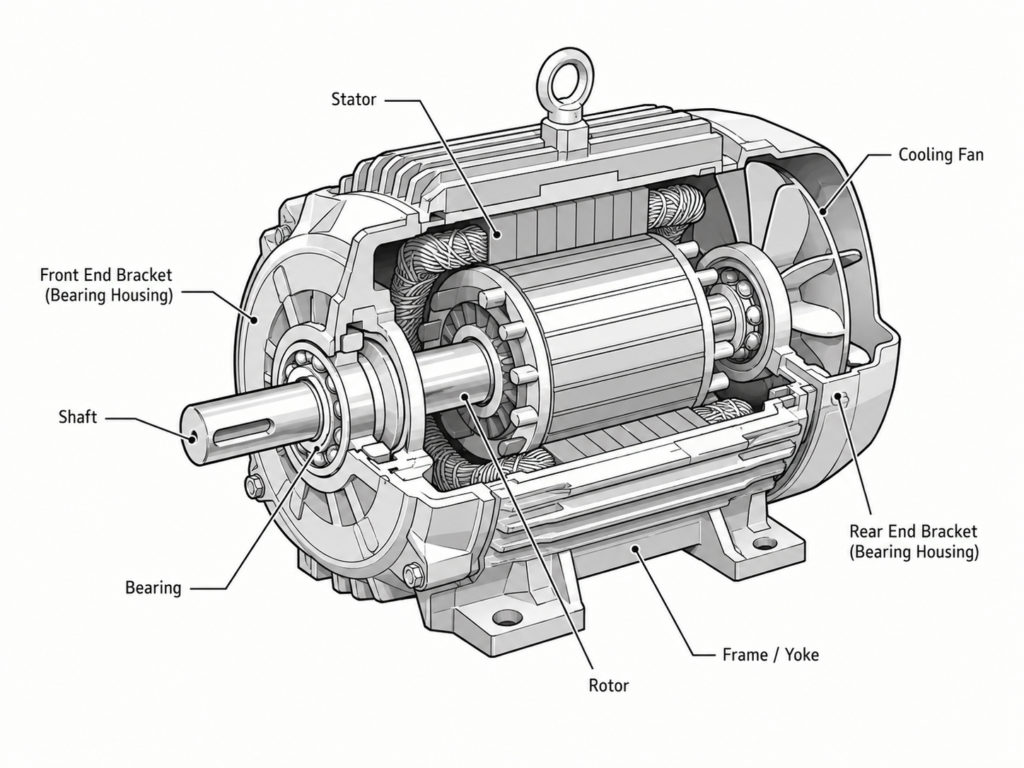
The stator is the stationary electrical portion of the motor. It is mounted securely inside the motor frame and does not rotate with the shaft.
Both the stator and rotor behave as electromagnetic circuits, but the stator receives electrical power directly from the supply.
A typical NEMA motor stator core is not manufactured from one solid chunk of steel. Instead, it is built from several hundred thin steel sheets known as laminations.
These laminations are stacked tightly together to form a hollow cylindrical core.
Why use hundreds of thin layers instead of one solid piece?
A solid steel core would allow larger circulating currents, known as eddy currents, to develop inside the metal. Those unwanted currents generate heat and waste energy. Dividing the core into insulated laminations restricts the current paths and helps reduce these losses.
It may look like someone sliced the motor core into an unreasonable number of metal pancakes, but there is a good electrical reason for it.
Stator Windings
Slots are formed around the inner surface of the laminated stator core. Coils made from insulated copper wire are carefully inserted into these slots.
The insulation is important. Without it, adjacent conductors could short together, the winding could connect electrically to the stator core, and the motor’s working life would likely become very short indeed.
Each group of coils, together with the steel section surrounding it, forms an electromagnet.
When three-phase voltage is applied to the windings, the current in each phase rises and falls at a different point in time. Because the phases are electrically separated by 120 degrees, their magnetic fields combine to create one smoothly rotating magnetic field inside the stator.
This rotating field is the heart of induction motor operation.
The stator windings are connected directly to the incoming electrical supply, either through a motor starter, contactor, variable-frequency drive, or another suitable motor control device.
Depending on the motor design and application, the windings may be connected in a star or delta configuration. Regardless of the exact connection, their purpose remains the same: create the magnetic field that pulls the rotor into motion.
The Rotor: Where Rotation Actually Happens
The rotor is the rotating part of the motor’s electromagnetic circuit. It sits inside the stator and is attached to the motor shaft.
Several rotor designs exist, but the most common construction used in standard industrial induction motors is the squirrel-cage rotor.
The name comes from its appearance. Early rotor designs resembled the spinning exercise wheels found inside cages for pet hamsters and other small rodents. Electrical engineering naming can be surprisingly literal sometimes.
A squirrel-cage rotor begins with a stack of thin steel laminations. Much like the stator laminations, these layers form a magnetic core while helping reduce eddy-current losses.
Slots are positioned evenly around the rotor’s outer circumference. Conductive bars, usually made from aluminum, are formed inside these slots.
In many motors, molten aluminum is die-cast directly into the rotor core. During the same casting process, conductive end rings are created at both ends of the rotor.
These end rings mechanically and electrically join all the conductor bars together.
The completed structure forms a closed conductive cage. There are no brushes, commutators, or direct electrical wires connected to the squirrel-cage rotor. Current appears in the rotor because it is induced by the stator’s rotating magnetic field.
That is where the name induction motor comes from.
How the Rotor Begins to Turn
When the stator’s magnetic field rotates past the rotor conductors, it cuts across the conductor bars and induces voltage in them.
Because the bars are connected through the end rings, current begins to flow around the rotor cage. That current produces its own magnetic field.
The magnetic interaction between the stator field and rotor field creates torque. The rotor then accelerates in the same direction as the rotating stator field.
As the rotor speeds up, the difference between rotor speed and magnetic-field speed becomes smaller. However, a small difference must always remain while the motor is producing torque.
Under a heavier mechanical load, the rotor slows slightly. Slip increases, more rotor current is induced, and the motor develops additional torque. It is a beautifully self-adjusting process, at least within the motor’s designed operating limits.
The Rotor Shaft and Rotor Assembly
The laminated rotor core is mounted onto a strong steel shaft. Together, the shaft, rotor core, conductor bars, and end rings form the complete rotor assembly.
The shaft transfers the motor’s mechanical output to the driven equipment.
Depending on the application, the shaft may connect to:
- A coupling
- A pulley
- A gearbox
- A pump impeller
- A fan
- A conveyor drive
The shaft must remain accurately aligned and properly supported. Even a small alignment problem can eventually cause vibration, excessive bearing wear, noise, or damage to connected machinery.
The Enclosure: More Than an Outer Shell
The enclosure is often treated as though it is merely the motor’s protective cover. It does provide protection, of course, but it also supports and aligns several important mechanical components.
A typical motor enclosure consists of:
- The main frame, sometimes called the yoke
- Two end brackets or bearing housings
- Bearings
- A cooling fan and fan cover
- A terminal box
The stator is fixed inside the main frame. The rotor sits inside the stator, separated from it by a very small air gap.
There is no direct physical contact between the stator and rotor.
That air gap must be maintained accurately around the entire circumference. If the rotor becomes misaligned because of bearing damage, a bent shaft, or mechanical wear, it may rub against the stator. This is sometimes called a rotor-to-stator rub, and it can cause serious damage surprisingly quickly.
Bearings and Rotor Support
Bearings are installed in the motor’s end brackets and fitted around the shaft. Their job is to support the rotor, maintain the correct air gap, and allow the shaft to turn with minimal friction.
Although bearings are relatively small compared with the rest of the motor, they have an outsized influence on motor reliability.
Poor lubrication, contamination, excessive belt tension, shaft misalignment, and electrical bearing currents can all shorten bearing life. A motor with damaged bearings may still run for a while, but it will often announce the problem through increased vibration, unusual noise, or rising temperature.
Ignoring those signs is rarely a money-saving strategy.
Cooling and Environmental Protection
The enclosure also protects the motor’s internal electrical and mechanical parts from the surrounding environment.
Depending on the enclosure type, the motor may be designed to resist:
- Dust
- Moisture
- Dirt
- Oil
- Accidental physical contact
- Other industrial contaminants
Many standard industrial motors use a shaft-mounted fan to move air across the outside of the motor frame. Cooling fins formed into the frame increase the available surface area, allowing heat to escape more effectively.
Motor temperature matters because excessive heat gradually damages winding insulation. The motor may continue operating, perhaps for months, but repeated overheating quietly shortens its service life.
For that reason, blocked ventilation openings, damaged fans, heavy dirt buildup, and frequent overloading should not be brushed aside.
The Three Main Parts Working Together
The construction of an AC induction motor can be reduced to three basic sections, but each section has a very specific role.
The stator receives three-phase electrical power and creates the rotating magnetic field.
The rotor responds to that field, develops torque, and turns the shaft.
The enclosure holds everything in alignment, supports the bearings, assists with cooling, and protects the internal components from the operating environment.
There is no electrical cable running to the squirrel-cage rotor and no direct contact between the rotating and stationary magnetic circuits. Energy crosses the air gap through electromagnetic induction.
Simple in principle. Clever in practice.
That combination of straightforward construction, relatively low maintenance, and reliable operation is one reason three-phase induction motors remain such a common sight in factories and industrial installations around the world.