The electricity arriving at a household socket may be around 120 or 230 volts, depending on the country.
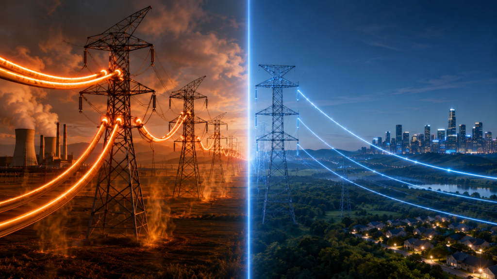
Look at a major transmission line, however, and the numbers become rather more intimidating: 110,000 volts, 220,000 volts, 400,000 volts, sometimes considerably higher.
Why send electricity across the country at voltages capable of producing enormous arcs, requiring giant insulators and keeping conductors high above the ground?
Because sending large amounts of power at low voltage would waste a ridiculous amount of energy.
For a given amount of transmitted power, increasing the voltage reduces the current. Lower current means less heating in the conductors, lower voltage drop, and more manageable cable sizes.
The entire high-voltage transmission system is built around that relationship.
Generate electricity at a practical voltage, step it up for efficient long-distance travel, then step it back down before customers use it.
Electrical Power Depends on Voltage and Current
In a simple electrical circuit, power can be expressed as:
Power = voltage × current
Or:
P = V × I
This means the same amount of power can be delivered using different combinations of voltage and current.
For example, 1,000 watts could theoretically be transmitted as:
- 100 volts at 10 amperes
- 1,000 volts at 1 ampere
- 10,000 volts at 0.1 ampere
Each combination represents the same electrical power.
The voltage changes. The current changes in the opposite direction.
If the required power remains constant, increasing the voltage allows the current to fall:
Current = power ÷ voltage
Or:
I = P ÷ V
That lower current is the reason high-voltage transmission works so well.
Power Lines Have Resistance
Transmission conductors are commonly made from aluminium, often reinforced with steel or another supporting structure.
Aluminium is a good conductor, but it is not perfect. Neither is copper. Every practical conductor has some electrical resistance.
Resistance depends on:
- The conductor material
- Its length
- Its cross-sectional area
- Its temperature
A long transmission line may stretch for tens or hundreds of kilometres. Even a low resistance per kilometre adds up over that distance.
When current flows through resistance, electrical energy is converted into heat.
The power lost in the conductor is:
Power loss = current² × resistance
Or:
P loss = I²R
The current is squared.
That one detail changes everything.
Why the Current-Squared Effect Matters
Suppose the current in a transmission line is reduced by half.
The losses do not merely fall by half.
Because current is squared:
(½)² = ¼
The line losses fall to one-quarter of their previous value.
Reduce the current to one-tenth and the losses become:
(1/10)² = 1/100
Only one-hundredth as large.
This is why raising transmission voltage produces such dramatic improvements. If voltage increases by a factor of ten while transmitted power remains unchanged, current falls by a factor of ten.
The resistive loss then falls by a factor of 100, assuming the same conductor resistance.
Higher voltage does not eliminate resistance. It makes far less current pass through that resistance.
A Simple Transmission Example
Imagine that we need to transmit 100 megawatts of electrical power.
For simplicity, we will first ignore three-phase details, power factor, and reactive effects.
At 10,000 volts:
I = 100,000,000 W ÷ 10,000 V
I = 10,000 A
That is an enormous current.
Now raise the transmission voltage to 400,000 volts:
I = 100,000,000 W ÷ 400,000 V
I = 250 A
The transmitted power remains 100 megawatts, but the current drops from 10,000 amperes to 250 amperes.
That is 40 times less current.
Because conductor loss depends on current squared, the theoretical resistive loss for the same line resistance becomes:
40² = 1,600 times lower
That is not a small improvement hidden in a spreadsheet. It is the difference between a practical transmission system and a very long outdoor heater.
Putting Line Resistance Into the Example
Suppose the total resistance of the transmission path is one ohm.
At 10,000 amperes, the conductor loss would be:
P loss = 10,000² × 1
P loss = 100,000,000 W
The line would waste 100 megawatts—the same amount of power we were trying to deliver.
Rather awkward.
At 250 amperes:
P loss = 250² × 1
P loss = 62,500 W
The loss becomes 62.5 kilowatts.
This is a deliberately simplified example, and real transmission systems involve three phases, multiple conductors, reactance, power factor, corona, and carefully calculated resistance values.
Still, it exposes the key principle beautifully:
High current is extremely expensive in terms of heat loss.
Three-Phase Transmission Power
Most large AC transmission systems use three-phase power.
For a balanced three-phase system, real power can be approximated by:
P = √3 × V × I × power factor
Here:
- P is real power
- V is line-to-line voltage
- I is line current
- Power factor describes how effectively current is converted into real power
Rearranging the formula:
I = P ÷ (√3 × V × power factor)
Once again, raising the line voltage reduces the current required to transmit a given amount of real power.
Three-phase systems also transfer power more smoothly and make efficient use of conductor material, which is why they dominate large electrical grids.
Lower Current Means Less Heat
When a conductor carries current, it warms up.
A small amount of heating is normal. Too much becomes a serious problem.
Excessive conductor temperature can cause:
- Greater line sag
- Faster material ageing
- Reduced mechanical strength
- Damage to insulation on cables
- Reduced transmission capacity
- Greater risk of faults
Overhead conductors expand as they heat. This causes them to sag lower between towers.
Transmission-line clearances are carefully designed so the conductors remain a safe distance from the ground, trees, buildings, vehicles, and other objects.
If current rises too high, the line may become hotter and sag farther than intended.
Reducing current therefore improves both efficiency and physical safety.
Resistance Increases With Temperature
There is another unpleasant detail.
The electrical resistance of common conductor metals increases as temperature rises.
More current creates more heat. More heat increases resistance. Higher resistance then creates even more heat for the same current.
Under normal operating conditions, the system reaches a manageable thermal balance. Under overload conditions, however, temperature can climb rapidly.
High-voltage transmission reduces the required current and helps keep this heating under control.
It breaks the cycle before the conductor begins behaving like a drooping electric radiator.
Lower Current Reduces Voltage Drop
Resistance does not only waste power. It also creates voltage drop.
The voltage dropped across a resistive conductor can be estimated using Ohm’s law:
Voltage drop = current × resistance
Or:
V drop = IR
Lower current means a smaller voltage drop across the same line resistance.
This helps maintain the receiving-end voltage closer to its intended value.
Voltage regulation becomes particularly important over long distances. If electricity were transmitted at low voltage and very high current, a substantial portion of the source voltage could disappear across the line before reaching the customer.
Increasing transmission voltage allows the system to deliver power over much greater distances with acceptable losses and voltage variation.
Could We Just Use Much Thicker Wires?
Yes, thicker conductors have lower resistance.
The resistance of a uniform conductor can be expressed as:
R = ρL ÷ A
Where:
- R is resistance
- ρ is the material’s resistivity
- L is conductor length
- A is cross-sectional area
Increasing the conductor area reduces resistance.
In theory, electricity could be transmitted at a lower voltage using enormous conductors.
In practice, this quickly becomes uneconomical.
Thicker conductors require:
- More aluminium or copper
- Stronger towers
- Larger supports
- More difficult installation
- Larger connectors
- Heavier switching equipment
- Greater transport and construction costs
A very large low-voltage conductor could also require many parallel cables, producing a rather absurd installation.
Raising voltage is generally a far more effective way to reduce current and losses than endlessly adding metal.
Lower Current Allows More Practical Conductors
A transmission conductor must satisfy several requirements at once.
It needs sufficient:
- Electrical conductivity
- Mechanical strength
- Thermal capacity
- Resistance to wind and ice loading
- Reliability over long distances
Using high voltage reduces the current requirement, allowing the line to transmit vast amounts of power without needing impossibly thick conductors.
The cables used on major lines are still substantial, of course. High-voltage transmission does not make them thin like telephone wires.
It simply keeps their size within realistic engineering and economic limits.
For very high currents, utilities may use multiple conductors per phase. These are called bundled conductors.
Bundling helps increase current capacity and also reduces certain high-voltage effects, including corona discharge.
Transformers Make High-Voltage AC Transmission Practical
The ability to change voltage efficiently is one of the great advantages of alternating current.
A transformer can step AC voltage up or down using electromagnetic induction.
At a generating station, electricity may be produced at a voltage in the range of several kilovolts to a few tens of kilovolts.
That voltage is practical for the generator itself, but it is too low for efficient transmission over long distances.
A step-up transformer raises it to transmission level.
The electricity may then travel through the grid at tens or hundreds of kilovolts.
Near cities and industrial areas, substations use transformers to reduce the voltage in stages.
The journey may look roughly like this:
- Electricity is generated at a moderate voltage.
- A transformer raises it to transmission voltage.
- High-voltage lines carry it across long distances.
- Grid substations reduce it to subtransmission levels.
- Distribution substations reduce it again.
- Local transformers provide the final customer voltage.
The exact voltage stages vary from one network to another.
The basic strategy is nearly universal: high voltage for transport, lower voltage for use.
Why Not Generate Electricity Directly at 400,000 Volts?
Generating electricity directly at extremely high voltage would create major design difficulties.
A generator winding operating at hundreds of kilovolts would require enormous insulation distances and extremely complex internal construction.
The machine would become larger, more expensive, and harder to cool and maintain.
It is more practical to generate at a moderate voltage and use a transformer to step the voltage up.
Transformers have no rotating parts and can change voltage with high efficiency.
They allow engineers to optimise the generator and transmission system separately rather than forcing one machine to do everything.
Why Is the Voltage Stepped Down Again?
A 400 kV transmission line is efficient, but it is not suitable for connecting directly to a refrigerator.
Extremely high voltage requires:
- Large insulation clearances
- Long air gaps
- Special switchgear
- Large bushings
- Careful electric-field control
- Strict access restrictions
- Specialised maintenance procedures
Household appliances, building wiring, switches, and sockets are not designed for those conditions.
Lower distribution voltages are easier and safer to insulate, control, and use.
Even 230 volts can be deadly. Hundreds of thousands of volts would be wildly unsuitable inside ordinary buildings.
So the grid uses the highest economically sensible voltage where efficiency matters most—during bulk transport—and progressively lowers it as power approaches the user.
Why Not Transmit at Infinite Voltage?
If higher voltage reduces current and resistive loss, why not keep increasing the voltage forever?
Because high voltage creates its own set of problems.
The higher the voltage, the more difficult and expensive the insulation becomes.
Greater voltage requires:
- Larger distances between conductors
- Longer insulator strings
- Taller and wider towers
- More expensive transformers
- Larger switchgear
- Greater substation clearances
- Better control of electric fields
- Increased protection against lightning and switching surges
At some point, the money saved through lower transmission losses is outweighed by the cost of building and maintaining the higher-voltage system.
Grid designers therefore choose voltage levels by balancing efficiency, distance, transmitted power, equipment cost, reliability, land use, and environmental effects.
The best voltage is not “as high as physically possible.”
It is the voltage that makes economic and technical sense for that particular route.
High Voltage Can Ionise Air
Air normally acts as an electrical insulator.
Under a sufficiently strong electric field, however, air molecules become ionised and begin conducting.
This can produce:
- Corona discharge
- Audible crackling or buzzing
- Radio interference
- Ozone formation
- Power loss
- Visible glow in dark conditions
Corona commonly forms around conductors where the electric field is strongest, especially near sharp points, damaged strands, connectors, and fittings.
Higher transmission voltage increases the risk.
Utilities reduce corona using smooth conductor surfaces, carefully shaped hardware, suitable conductor spacing, and bundled conductors.
The goal is not simply to keep electricity inside the wire. At very high voltages, the surrounding electric field becomes an engineering problem of its own.
Insulators Must Become Larger
Overhead conductors are supported by insulators made from materials such as porcelain, glass, or polymers.
The insulator must prevent current from flowing from the conductor into the grounded tower.
As voltage increases, the required insulation distance generally increases too.
Designers must account for:
- Normal operating voltage
- Lightning impulses
- Switching surges
- Rain
- Ice
- Salt contamination
- Industrial pollution
- Dust
- Altitude
A dirty or wet insulator surface can allow leakage current to flow. In severe conditions, an arc may travel across the surface in an event called flashover.
This is why high-voltage insulators have long, ribbed shapes. The ribs increase the surface path, known as the creepage distance, and help maintain insulation under contaminated conditions.
They are not decorative, although they do have a rather distinctive industrial style.
Transmission Towers Need Large Clearances
High voltage can arc through air before a conductor physically touches another object.
Transmission towers must therefore maintain sufficient distance between:
- Individual phases
- Conductors and the tower
- Conductors and the ground
- Conductors and nearby buildings
- Conductors and vegetation
The required distances become greater as voltage rises.
This is one reason high-voltage towers are so large. Their size is not determined only by the weight of the conductors.
They are also giant spacing devices, keeping energised parts far enough apart that the air remains an effective insulator.
AC Transmission Has Reactive Effects
Real transmission lines are not purely resistive.
They also have:
- Inductance
- Capacitance
- Reactive power flow
- Electric and magnetic fields
- Frequency-dependent behaviour
At high voltages and over long distances, these effects become significant.
Line inductance contributes to voltage drop and reactive power demand. Line capacitance can generate reactive power, especially on lightly loaded long lines and underground cables.
Utilities use equipment such as:
- Shunt reactors
- Capacitor banks
- Synchronous compensators
- Static VAR compensators
- STATCOM systems
- Series compensation
These devices help control voltage, improve power transfer, and manage reactive power.
So although higher voltage reduces resistive losses, it does not make long-distance AC transmission electrically simple.
It merely makes it possible.
Why Underground High-Voltage Cables Are Different
Underground cables have conductors placed relatively close to grounded screens, with solid insulation between them.
This construction creates much greater capacitance than an overhead line.
The cable draws charging current even when the connected load is small. On long AC cable routes, that charging current can consume a substantial part of the cable’s current-carrying capacity.
Heat is also harder to remove underground than from a bare conductor suspended in open air.
For these reasons, long underground or subsea connections may use high-voltage direct current rather than AC.
HVDC avoids continuous AC cable-charging current and can be more efficient for certain long-distance projects.
High-Voltage Direct Current
High-voltage direct current, usually called HVDC, is used for some long-distance transmission links.
In an HVDC system, converter stations change AC into DC for transmission and then convert it back to AC at the receiving end.
HVDC can offer several advantages:
- Lower losses over very long routes
- No AC reactive power flow along the line
- No continuous cable-charging current
- Controlled power transfer
- Connection between unsynchronised AC grids
- Efficient long submarine cable links
The converter stations are expensive and complex, so HVDC is not automatically best for every project.
For shorter distances and ordinary interconnected networks, AC transmission remains extremely practical because transformers make voltage conversion straightforward.
For long point-to-point routes, subsea cables, and certain grid connections, HVDC may win.
Different problem, different tool.
Does High Voltage Save Energy by Itself?
Not quite.
Simply raising voltage without changing anything else does not magically create efficiency.
The important change is that, for the same transmitted power, increasing voltage allows current to decrease.
It is the reduced current that lowers resistive losses.
This distinction matters.
An energised high-voltage line carrying little or no useful power can still experience corona, dielectric losses, leakage, and reactive effects.
The efficiency benefit appears when high voltage is used to transmit a given amount of power at lower current.
A Useful Comparison With Water
Imagine transporting a fixed amount of hydraulic power through a pipe.
One option uses low pressure and an enormous flow rate. The pipe must be huge, and frictional losses become severe.
The other uses much higher pressure and a lower flow rate. The system can transfer the same power with a more manageable volume of moving fluid.
Voltage is somewhat like pressure.
Current is somewhat like flow rate.
The comparison is not perfect—electricity is not water hiding inside copper pipes—but it captures the central idea.
For bulk power transmission, engineers raise the electrical pressure so they do not need an overwhelming electrical flow.
Why Transmission Losses Can Never Be Zero
Even at very high voltage, some energy is lost.
Losses occur in:
- Transmission conductors
- Transformers
- Switchgear
- Cable insulation
- Corona discharge
- Reactive current
- Converter stations
- Connections and busbars
Grid operators can reduce these losses, but eliminating them completely would require zero resistance and perfect equipment.
Superconductors can carry current with extremely low electrical resistance under specialised conditions, but they require cooling and remain impractical for most ordinary power-grid routes.
Real electrical systems always involve compromise.
The aim is not zero loss. The aim is an economically reasonable level of loss while maintaining reliability, safety, and acceptable power quality.
The Main Point
Electricity is transmitted at extremely high voltage because high voltage allows the same amount of power to be carried with much lower current.
For constant power:
Higher voltage = lower current
Lower current then produces:
- Much lower resistive heating
- Lower transmission losses
- Reduced voltage drop
- More practical conductor sizes
- Greater power-transfer capacity
The benefit is especially powerful because conductor losses depend on the square of current.
Double the transmission voltage and current is cut roughly in half. Resistive losses fall to about one-quarter, assuming the same transmitted power and conductor resistance.
Increase voltage tenfold and the current falls to one-tenth. The losses fall to approximately one-hundredth.
That is why power leaves generating stations, passes through step-up transformers, and travels across the grid at tens or hundreds of thousands of volts.
Once it reaches the areas where people and machines will use it, transformers step the voltage down again.
High voltage makes the journey efficient.
Lower voltage makes the destination practical.