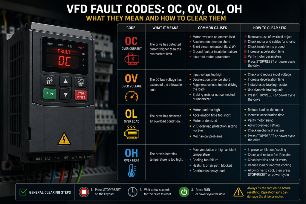
Four letters can stop an entire machine.
OC. OV. OL. OH.
The motor stops, the VFD display begins flashing, and production suddenly becomes very interested in whoever is standing closest to the control cabinet.
These fault codes commonly refer to:
- OC: Overcurrent
- OV: Overvoltage
- OL: Overload
- OH: Overheat or overtemperature
Simple enough—until you try to find the actual cause.
An OC fault could come from a jammed conveyor, an acceleration ramp that is too short, damaged motor wiring or an incorrectly configured motor. OV may have nothing to do with the VFD’s incoming voltage and everything to do with a heavy load regenerating energy during deceleration. OL can describe motor thermal overload, inverter overload or a calculated electronic thermal condition. OH may refer to the drive heatsink, motor, power stage or control board.
Manufacturers do not use these abbreviations in exactly the same way. One drive may display OC1, OC2 and OC3 for overcurrent during acceleration, deceleration and constant-speed operation. Another may use a numbered alarm instead of letters. Siemens, ABB, Danfoss, Schneider Electric, Delta, Mitsubishi, Yaskawa and Invertek all organise faults differently.
So treat the four abbreviations as categories, not universal diagnoses.
The display gives you a direction. The full fault record and manufacturer’s manual tell you where to look.
Before Resetting Any VFD Fault
A fault reset is not a repair.
Pressing RESET may clear the display, but it does not remove a jammed load, repair damaged insulation or clean a blocked cooling fan. Repeatedly resetting a drive into the same fault can place additional stress on the motor, VFD power stage and connected machinery.
Before attempting a reset:
- Put the machine in a safe condition.
- Record the complete fault code and any subcode.
- Note whether it happened during starting, acceleration, steady running, deceleration or stopping.
- Record motor current, speed and load if available.
- Check the VFD’s fault history.
- Identify any recent mechanical, electrical or parameter changes.
- Correct the likely cause before restarting.
Do not disconnect motor wiring or open the VFD immediately after removing incoming power. Its internal DC-link capacitors can retain a dangerous voltage. Follow the manufacturer’s isolation procedure, wait the specified discharge time and verify the absence of voltage using suitable test equipment.
The dark display is not proof that the DC bus is safe.
VFD Fault Codes Are Not Fully Standardised
The four common abbreviations provide a useful starting point, but their exact meanings vary.
For example:
OLmay mean motor overload on one drive and inverter overload on another.OHmay refer to heatsink temperature, internal power-stage temperature or motor temperature.OVmay appear as DC-bus overvoltage rather than input-supply overvoltage.OCmay be separated into acceleration, deceleration and constant-speed faults.- A warning may allow continued operation, while a trip disables the output.
- A trip-lock may require a power cycle or another manufacturer-specific reset procedure.
Danfoss documentation, for example, distinguishes warnings, trips and trip-lock conditions, while Siemens and Schneider drives provide detailed numbered faults rather than relying only on two-letter abbreviations. rite down the entire display message.
“VFD shows OL” is useful.
“VFD shows OL2 after 18 seconds at 43 Hz while the conveyor is loaded” is much better.
OC Fault: Overcurrent
An OC fault means the VFD detected current above an allowed limit.
This usually happens quickly. The current rises sharply, the drive’s protection responds and the output is switched off before the power transistors, motor or cables suffer serious damage.
Overcurrent is not the same as overload.
An overcurrent trip is often an immediate response to a large current spike. Overload protection normally reacts to excessive current accumulated over time through a thermal model. Schneider’s documentation makes this distinction explicitly: overcurrent reacts when a current threshold is exceeded, while power-stage overload considers thermal loading over a period. n Causes of an OC Fault
Acceleration is too fast
A motor needs torque to accelerate its load.
Torque requires current. If the VFD tries to bring a heavy conveyor, fan, mixer or flywheel to full speed too quickly, the requested current may exceed the drive’s limit.
This is especially common with:
- high-inertia loads;
- loaded conveyors;
- centrifuges;
- crushers;
- mixers;
- large fans;
- positive-displacement pumps;
- machines starting under mechanical pressure.
The machine is jammed
A blocked pump, seized bearing, trapped product or mechanically locked conveyor can prevent the motor from accelerating.
The drive continues trying to create torque, motor current rises and an OC trip follows.
Motor wiring has a short circuit
Damaged insulation can create:
- phase-to-phase short circuits;
- phase-to-earth faults;
- intermittent faults that appear only during vibration;
- terminal-box flashover;
- cable faults caused by crushing or sharp bends.
Power-stage overcurrent can be caused by short circuits or incorrect control settings, and related manufacturer diagnostics may separately identify ground faults or output-stage short circuits. motor cable is damaged or incorrectly connected
Loose motor terminals, incorrect star-delta links, damaged cables and poor connections can create unbalanced or excessive current.
A motor intended for one connection may draw abnormal current if connected incorrectly for the available drive output voltage.
Motor data is wrong
Vector-control drives rely on motor nameplate information and, in many cases, an identification or autotune procedure.
Incorrect values for rated current, voltage, frequency, speed or power factor can cause poor flux control and excessive current.
Siemens fault guidance for drive-current problems includes checking motor data, commissioning and star-delta circuit configuration, as well as increasing the acceleration ramp where appropriate. age boost is too high
Manual low-speed voltage boost can improve starting torque, but too much boost may over-magnetise the motor.
The result can be:
- excessive current;
- motor heating;
- magnetic saturation;
- rough operation;
- an OC trip at low speed.
The motor is switched on the VFD output
Opening or closing a contactor between a running VFD and motor can create severe current transients.
Unless the manufacturer and control design explicitly permit output switching, the motor should normally be connected before the VFD is enabled and remain connected while the drive produces output.
The VFD is undersized
A small drive may run a lightly loaded motor successfully but trip when the machine reaches its real process load.
The drive must be selected for:
- motor rated current;
- overload requirement;
- duty cycle;
- ambient temperature;
- switching frequency;
- application type.
Matching only the motor’s kilowatt rating is not always enough.
How to Clear an OC Fault
Start by removing the run command and placing the machine in a safe state.
Then:
- Check for a mechanical jam or seized load.
- Confirm that the motor rotates freely when safely disconnected from the process where appropriate.
- Inspect the motor cable and terminal box.
- Check for phase-to-phase and phase-to-earth insulation faults using suitable test methods.
- Verify motor star-delta links.
- Confirm all motor nameplate parameters.
- Perform the manufacturer’s autotune procedure if required.
- Increase acceleration time.
- Reduce excessive torque boost.
- Check current-limit and vector-control settings.
- Confirm the drive is correctly sized.
- Reset only after the cause has been corrected.
If OC appears immediately when the drive is enabled, suspect the motor cable, motor windings, power stage or severe configuration error.
If it appears during acceleration, investigate ramp time, load inertia and starting torque.
If it appears only at one speed, check for mechanical resonance, binding or a process load that increases sharply at that operating point.
If it appears even with the motor cable safely disconnected, the VFD’s output stage may be defective. Follow the manufacturer’s test procedure rather than assuming that result alone proves internal failure.
OV Fault: Overvoltage
An OV fault usually means the voltage inside the VFD’s DC link has risen above its permitted limit.
People often assume this means the incoming mains supply is too high.
Sometimes it is.
Very often, though, OV occurs while the motor is slowing down.
Why Deceleration Can Create Overvoltage
A spinning motor and its connected load contain mechanical energy.
When the VFD commands rapid deceleration, the motor can operate as a generator. Energy flows from the rotating load back into the drive’s DC bus.
If the VFD cannot use, store or dissipate that energy quickly enough, the DC-link voltage rises until the overvoltage protection trips.
Siemens identifies excessive regenerated motor energy and high device-supply voltage as causes of DC-link overvoltage. quently happens with:
- high-inertia fans;
- centrifuges;
- large rollers;
- downhill conveyors;
- hoists;
- suspended loads;
- flywheels;
- rapidly stopping machinery.
The VFD is not objecting to the motor running.
It is objecting to being used as an energy-storage device without anywhere for that energy to go.
Common Causes of an OV Fault
Deceleration ramp is too short
A short ramp asks the motor to return energy rapidly.
Extending the deceleration time reduces the regenerative power flowing into the DC bus.
Incoming voltage is too high
Supply voltage may exceed the drive’s permitted range because of:
- incorrect transformer tapping;
- light loading on the distribution system;
- utility voltage variation;
- incorrect drive voltage class;
- poor generator regulation;
- regenerative equipment on the same bus.
Measure all input phases and compare the results with the VFD rating.
Braking resistor is missing or incorrectly sized
Applications requiring fast stops may need a braking resistor and, where applicable, a braking chopper.
The resistor converts regenerated energy into heat.
A resistor with the wrong resistance or insufficient power rating may not absorb the required energy safely. Braking resistor selection must follow the manufacturer’s permitted resistance, power and duty-cycle limits.
Braking circuit has failed
Possible problems include:
- open resistor;
- damaged wiring;
- tripped thermal switch;
- failed braking transistor;
- incorrect braking parameters;
- resistor disconnected during maintenance.
Load drives the motor
A downhill conveyor, overhauling hoist or externally driven process may continuously regenerate energy.
Increasing the deceleration ramp will not solve continuous regeneration. The system may require a regenerative drive, braking unit or another application-specific solution.
Supply disturbances
Switching events, capacitor banks and other equipment can produce temporary voltage rises.
The VFD’s fault history may show whether the condition occurs randomly or at the same stage of every machine cycle.
How to Clear an OV Fault
After the DC-bus voltage returns to a normal level:
- Increase the deceleration time.
- Check the incoming voltage on all phases.
- Confirm the VFD voltage rating.
- Inspect the braking resistor and wiring.
- Check braking-resistor resistance only after safe isolation and discharge.
- Verify braking-chopper parameters.
- Review the load’s regenerative behaviour.
- Enable overvoltage control where supported and appropriate.
- Consider a braking resistor, braking unit or regenerative drive.
- Reset after the cause has been addressed.
Danfoss documentation notes that overvoltage control can help prevent trips by extending or modifying the deceleration behaviour, but this can lengthen stopping time. de-off matters.
A longer stop may prevent an electrical trip but may not be acceptable for the process or machine-safety design. Do not change stopping behaviour without considering the risk assessment and required stop time.
OL Fault: Overload
An OL fault generally means the motor or VFD has been carrying excessive load for too long.
Unlike an OC trip, overload protection usually follows a thermal model. The drive estimates heating based on current, time, operating speed and configured motor information.
A motor may briefly draw more than rated current during acceleration without tripping. Continue drawing that current, and the calculated temperature rises until the drive issues an OL fault.
OL Can Refer to Different Things
Depending on the manufacturer, OL may mean:
- motor overload;
- inverter overload;
- electronic thermal overload;
- torque overload;
- braking resistor overload;
- process overload.
Some drives distinguish these with codes such as:
OL1for motor overload;OL2for drive overload;OL3for excessive torque.
Others use completely different fault numbers.
Read the full description before changing settings.
Common Causes of an OL Fault
The machine is mechanically overloaded
Possible examples include:
- too much product on a conveyor;
- blocked material flow;
- excessive pump pressure;
- closed valve;
- damaged gearbox;
- overtightened belt;
- worn or seized bearings;
- mixer filled beyond its design;
- cutting tool pushed too aggressively.
The motor is undersized
A motor can run below rated speed and still be overloaded.
Compare the actual process torque and current with the motor’s continuous rating. A motor that repeatedly operates near or above rated current may simply be too small for the job.
The VFD is undersized
A drive’s normal-duty rating may differ from its heavy-duty rating.
An application requiring high starting torque or frequent overload may need a larger drive even when the motor’s nominal kilowatt rating appears to match.
Acceleration occurs too frequently
Repeated starts can build thermal load even when each individual acceleration completes successfully.
The drive’s electronic thermal model remembers the accumulated heating.
Motor parameters are incorrect
If the configured motor current is lower than the actual nameplate current, the drive may calculate overload too early.
If the setting is raised above the correct value merely to stop nuisance trips, the motor may lose protection.
Enter the real nameplate values.
Do not turn the overload setting into a optimism dial.
The motor runs too slowly without enough cooling
A standard shaft-mounted motor fan moves less air at low speed.
The VFD may deliver rated torque, and therefore substantial current, while the motor’s cooling fan barely turns. Continuous low-speed operation can overheat the motor even when current is not dramatically above its nameplate rating.
Possible solutions include:
- an independently powered motor fan;
- reduced low-speed torque;
- a larger motor;
- inverter-duty motor selection;
- direct temperature monitoring.
Supply or output phase problem
A loose connection, damaged winding or phase imbalance may increase current in the remaining phases.
Check individual phase currents rather than relying only on one overall display value.
Excessive voltage drop
Long or undersized motor cables can reduce available motor voltage and increase current under load.
Poor terminals can produce a similar effect while also creating local heating.
How to Clear an OL Fault
An overload fault may not reset immediately because the drive’s thermal model needs time to cool.
Use this sequence:
- Remove or reduce the mechanical load.
- Allow the motor and VFD to cool.
- Check actual motor current on all phases.
- Compare operating current with motor and drive ratings.
- Inspect bearings, belts, gearbox and driven equipment.
- Verify motor nameplate parameters.
- Check motor cooling at low speed.
- Review acceleration frequency and duty cycle.
- Confirm the VFD’s normal-duty or heavy-duty rating.
- Reset only after the thermal condition has fallen below the restart threshold.
Siemens guidance for overload and overtemperature conditions includes reducing continuous load, adapting the duty cycle and checking whether motor and power-unit current ratings suit the application. ncrease the electronic overload threshold beyond the motor’s safe rating simply because production wants the machine running.
The original trip may be inconvenient.
A burnt motor at the end of the shift is generally more inconvenient.
OH Fault: Overheat or Overtemperature
An OH fault means a monitored temperature has exceeded its allowed limit.
The monitored location may be:
- VFD heatsink;
- power module;
- control card;
- internal air;
- motor winding;
- braking resistor;
- external temperature sensor.
The exact code description matters.
A drive-heatsink overtemperature fault and a motor-thermistor fault require different troubleshooting.
Common Causes of an OH Fault
Cooling fan has stopped
VFD cooling fans wear out.
Bearings deteriorate, blades become blocked and fan connectors loosen. Some fans operate only when temperature or load reaches a threshold, so a stationary fan on a cold idle drive is not automatically faulty.
Check whether it starts when commanded and whether the drive reports fan status.
Heatsink or air filter is blocked
Dust, fibres, oil mist and production debris reduce airflow.
A drive may run normally for months before the gradual buildup pushes it beyond its thermal limit on a warm day.
Cabinet temperature is too high
The VFD can only transfer heat into its surroundings when the surrounding air is cooler than the drive.
Common cabinet problems include:
- failed extraction fan;
- blocked intake filter;
- undersized air conditioner;
- closed ventilation openings;
- several drives mounted too closely;
- sunlight heating an outdoor cabinet;
- hot braking resistor mounted nearby;
- incorrect enclosure design.
Drive is overloaded
More current produces greater semiconductor and conductor losses.
A drive operating continuously near its limit will run hotter than one with comfortable spare capacity.
Carrier frequency is too high
Higher PWM switching frequency can reduce audible motor noise, but it increases switching losses in the VFD.
Danfoss documentation notes that drive power losses rise significantly at higher switching frequencies. r-frequency change made to silence a whistling motor can therefore contribute to an OH trip, particularly in a warm cabinet or heavily loaded application.
Installation clearances are inadequate
Drives need specified free space for ventilation.
Placing cable ducts, contactors or another VFD directly against an air inlet can restrict cooling even when the cabinet fan works correctly.
Ambient temperature exceeds the rating
VFD output current may require derating at high ambient temperature.
A drive capable of full current at 40°C may not provide the same continuous output at a higher cabinet temperature.
Motor temperature sensor has tripped
If the OH code refers to the motor, inspect:
- actual motor temperature;
- load;
- cooling;
- thermistor or RTD wiring;
- configured sensor type;
- alarm threshold;
- low-speed operation;
- motor fan.
Siemens’ motor-overtemperature remedies include reducing the load, checking ambient temperature and ventilation, and inspecting the temperature-sensor wiring. erature sensor or wiring is faulty
A broken thermistor cable, wrong sensor configuration or loose terminal can create a false temperature trip.
Do not bypass the sensor without determining why it operated.
How to Clear an OH Fault
- Stop the drive and allow it to cool.
- Check the exact monitored temperature channel.
- Confirm that cooling fans operate.
- Clean filters and heatsinks safely.
- Verify cabinet temperature and airflow.
- Restore required mounting clearances.
- Reduce motor or drive load.
- Check switching-frequency derating.
- Inspect motor ventilation.
- Test temperature-sensor wiring.
- Confirm temperature-sensor parameters.
- Reset only after the temperature falls below the restart level.
Siemens drive guidance for power-stage thermal faults includes checking the load-duty cycle and verifying that fans and fan components operate properly. turns quickly from a cold start, suspect:
- failed temperature sensor;
- incorrect sensor configuration;
- blocked or non-running fan;
- internal drive defect;
- a load producing extreme current immediately.
How to Reset a VFD Safely
Once the cause has been removed, a VFD may be reset through one of several methods:
- keypad RESET or STOP/RESET button;
- digital input assigned to fault reset;
- PLC command;
- fieldbus control word;
- remote operator panel;
- power cycle.
The permitted method depends on the drive and fault category.
Some faults clear automatically when the condition disappears. Others remain latched until a reset command is received. Serious faults may create a trip-lock requiring incoming power to be removed after safe shutdown and inspection.
Never assume every fault should be automatically reset.
Automatic restart can be dangerous if the machine begins moving when:
- a jam clears;
- the drive cools;
- supply voltage returns;
- communication is restored;
- an operator is still working near the machine.
The reset strategy must match the machine’s safety design.
A General Reset Sequence
- Remove the run command.
- Place the machine in a safe condition.
- Record the fault and operating circumstances.
- Correct the cause.
- Ensure personnel are clear of hazardous areas.
- Reset the VFD.
- Confirm that the fault display clears.
- Start at low load where practical.
- Monitor current, DC-bus voltage and temperature.
- Confirm normal operation through the full machine cycle.
If the code returns, stop resetting it and continue diagnosing.
The drive has already voted twice.
Quick Diagnostic Guide
OC during acceleration
Likely areas:
- acceleration ramp too short;
- high-inertia load;
- mechanical jam;
- excessive torque boost;
- incorrect motor data;
- undersized VFD.
Try:
- checking the load;
- increasing acceleration time;
- confirming motor parameters;
- performing autotune;
- checking motor current.
OC immediately at start
Likely areas:
- motor cable short circuit;
- earth fault;
- damaged motor winding;
- incorrect motor connection;
- defective output stage.
Try:
- isolating and testing the motor circuit;
- checking star-delta links;
- following the manufacturer’s output-stage test.
OV during deceleration
Likely areas:
- deceleration ramp too short;
- high-inertia load;
- missing braking resistor;
- failed braking circuit;
- regenerative load.
Try:
- increasing deceleration time;
- checking the braking resistor;
- enabling approved overvoltage control;
- evaluating regenerative braking requirements.
OV while idle or running steadily
Likely areas:
- incoming voltage too high;
- supply transients;
- incorrect voltage-class drive;
- unstable generator supply.
Try:
- measuring input voltage;
- checking transformer taps;
- monitoring supply disturbances.
OL after several minutes
Likely areas:
- excessive process load;
- motor or drive undersized;
- poor motor cooling;
- incorrect overload setting;
- bearing or gearbox problem.
Try:
- measuring running current;
- reducing load;
- checking mechanical resistance;
- reviewing duty cycle;
- confirming drive sizing.
OH on hot days
Likely areas:
- cabinet temperature too high;
- blocked filters;
- failed ventilation fan;
- insufficient derating;
- high switching frequency.
Try:
- cleaning cooling paths;
- measuring cabinet temperature;
- checking fans;
- reviewing installation clearances and derating.
OH immediately from cold
Likely areas:
- faulty temperature sensor;
- broken sensor cable;
- incorrect sensor type;
- internal drive fault.
Try:
- checking live temperature readings;
- inspecting sensor wiring;
- verifying parameters;
- contacting the manufacturer if the reading is implausible.
Parameters Worth Checking
The exact parameter numbers vary, but these functions are commonly relevant:
- motor rated voltage;
- motor rated current;
- motor rated frequency;
- motor rated speed;
- motor rated power;
- acceleration time;
- deceleration time;
- current limit;
- torque limit;
- electronic thermal protection;
- motor thermal model;
- voltage boost;
- carrier frequency;
- overvoltage control;
- braking resistor settings;
- motor temperature-sensor type;
- automatic restart;
- fault-reset input;
- autotune or motor identification.
Change one parameter at a time and record the original value.
Changing six settings together may make the fault disappear, but it also ensures that nobody knows why.
When the VFD May Be Defective
Internal VFD failure becomes more likely when:
- OC appears with the motor disconnected according to the manufacturer’s test procedure;
- OH appears from a cold start with impossible temperature readings;
- cooling fans and sensors are confirmed healthy;
- the DC-bus reading is clearly incorrect;
- faults occur without any output command;
- there is visible damage or a burnt smell;
- the power stage repeatedly trips with a known-good motor and cable;
- the fault cannot be reset using the documented procedure.
Before replacing the drive, verify:
- incoming voltage;
- motor insulation;
- cable condition;
- grounding;
- parameter backup;
- load condition;
- braking circuit;
- cabinet cooling.
A new VFD connected to the same damaged motor cable may last only long enough to make the diagnosis considerably more expensive.
Do Not Clear the Code—Clear the Cause
The four common VFD faults describe different kinds of electrical or thermal stress:
- OC means current became too high, usually very quickly.
- OV means the DC-bus voltage exceeded its limit, often because of regenerated braking energy.
- OL means excessive load accumulated over time.
- OH means a monitored temperature became too high.
They are related, too.
A jammed machine can create OC during starting or OL after prolonged operation. Excessive load can heat the drive until OH appears. An aggressive deceleration ramp can turn a perfectly healthy motor into a generator and produce OV.
That is why timing matters.
Record exactly when the trip occurs, inspect the fault history and compare the event with the machine sequence. Then check the mechanical load, motor circuit, power supply, cooling system and relevant parameters.
Resetting the VFD is usually easy.
Making sure the fault does not return is the actual job.