A contactor should normally pull in with one firm click and remain engaged until its coil is de-energised.
A faint hum from an AC contactor can be normal. Loud buzzing, rapid clicking or repeated opening and closing is not.
Contactor chattering happens when the magnetic system cannot hold the armature firmly closed or when the coil command repeatedly switches on and off. The contactor may pull in, drop out and immediately pull in again—sometimes several times per second.
This is more than an irritating noise.
Chattering can cause:
- burned or welded main contacts;
- damaged auxiliary contacts;
- overheated coils;
- motor voltage interruptions;
- nuisance overload trips;
- PLC input instability;
- mechanical wear;
- complete contactor failure.
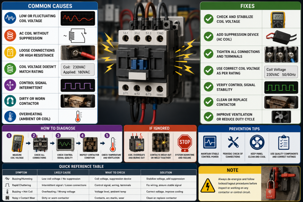
The most common causes are low coil voltage, the wrong coil rating, loose control wiring, a dirty or damaged armature and an unstable PLC output.
The sound provides a clue, but the real diagnosis begins by measuring the voltage directly across the coil while the fault is happening.
Buzzing and Chattering Are Not Exactly the Same
The two terms are often used together, but they can describe different behaviour.
Normal AC hum
A small amount of humming may be normal in an energised AC contactor. Its coil creates an alternating magnetic field, and the magnetic components can vibrate slightly.
The sound should be quiet and steady.
Loud buzzing
A contactor that remains closed but produces a loud buzz may have:
- dirt between the magnetic faces;
- a damaged shading ring;
- a loose or misaligned armature;
- low coil voltage;
- an incorrect supply frequency;
- damaged laminations;
- a worn contactor mechanism.
Chattering
A chattering contactor repeatedly pulls in and drops out.
The sound is usually a rapid series of clicks or clacks rather than one continuous hum.
This normally indicates:
- unstable coil voltage;
- a broken or loose control connection;
- rapidly changing PLC logic;
- a bouncing sensor or switch;
- an incorrect coil supply;
- insufficient magnetic holding force.
One click followed by immediate release
If the contactor pulls in once and then releases, the coil voltage may be collapsing when the main load starts.
This can happen when:
- the control transformer is undersized;
- the supply voltage drops;
- the control cable is too long;
- another large coil energises at the same time;
- a seal-in auxiliary contact is not closing;
- the control circuit is wired incorrectly.
The exact sound matters because it helps separate a mechanical buzz from an electrical command that is repeatedly disappearing.
How an AC Contactor Stays Closed
When voltage is applied to the coil, current creates a magnetic field.
That field pulls the movable armature toward the fixed magnetic core. The movement closes the main contacts and usually changes the state of one or more auxiliary contacts.
Once the armature is fully closed, the magnetic circuit becomes much more efficient. The coil generally needs less current to hold the contactor closed than it needed during initial pull-in.
An AC magnetic field passes through zero twice during every electrical cycle. Without special construction, the armature could attempt to release at every zero crossing.
AC contactors therefore commonly use a shading ring—a conductive ring embedded in part of the magnetic pole face. It creates a slightly delayed magnetic flux that helps maintain holding force while the main flux passes through zero.
If the shading ring is cracked, loose or missing, the contactor may buzz loudly even when the supply voltage is correct.
Why Chattering Damages the Contactor
Main contacts are designed to close quickly and firmly.
During chattering, they repeatedly touch and separate while current may be flowing. Each interruption can produce an electrical arc.
Repeated arcing causes:
- contact erosion;
- pitting;
- carbon deposits;
- overheating;
- contact welding;
- phase imbalance.
If the contactor controls a three-phase motor, the three poles may not make and break identically. The motor can briefly receive an unbalanced supply or lose one phase.
That may lead to:
- motor humming;
- reduced torque;
- high phase current;
- overload trips;
- winding overheating.
The coil also suffers. Every time the contactor drops out, it must attempt another high-current pull-in. Continuous pull-in attempts can overheat and eventually burn the coil.
A chattering contactor should not be left operating while someone waits to see whether it settles down.
It usually does not improve with practice.
Quick Troubleshooting Table
| Symptom | Most likely causes |
|---|---|
| Quiet, steady hum | Often normal for an AC contactor |
| Loud buzz while staying closed | Dirty pole faces, damaged shading ring, low voltage, misalignment or loose magnetic parts |
| Rapid repeated clicking | Low or unstable coil voltage, loose wiring, bouncing command or rapidly switching PLC output |
| Pulls in and immediately drops out | Voltage collapse, failed seal-in circuit, wrong coil rating or open auxiliary holding contact |
| Chatters only when the motor starts | Control-voltage sag, undersized transformer, shared supply problem or long-cable voltage drop |
| Chatters randomly | Loose terminal, intermittent sensor, damaged wire, vibration or unstable PLC logic |
| Coil becomes extremely hot | Incorrect voltage, AC coil supplied with DC, excessive switching or damaged coil |
| Buzzes even at correct voltage | Dirty armature, damaged shading ring, warped mechanism or worn contactor |
1. Low Coil Voltage
Low coil voltage is one of the most common causes of contactor chattering.
The coil may receive enough voltage to begin pulling the armature in but not enough to close it firmly.
The sequence can become self-repeating:
- Voltage reaches the coil.
- The armature starts moving.
- The contactor closes partially.
- Supply voltage drops or magnetic force remains insufficient.
- The armature releases.
- Voltage recovers.
- The contactor pulls in again.
That creates the familiar rapid clicking.
Common reasons for low coil voltage
- weak control transformer;
- overloaded control-power supply;
- low mains voltage;
- excessive cable voltage drop;
- loose terminal;
- high-resistance contact;
- undersized control wiring;
- several coils energising simultaneously;
- wrong transformer tap;
- partially failed rectifier;
- damaged control relay contact.
Measure voltage at the coil—not only at the source
The most useful measurement is taken directly across coil terminals A1 and A2 while the contactor is attempting to operate.
A control transformer may show its correct rated voltage with no load. The voltage can collapse when the coil is energised.
Measure:
- voltage before the Start command;
- voltage during pull-in;
- voltage while the contactor is held;
- voltage while other machine loads operate.
Compare the result with the voltage and frequency printed on the coil or contactor nameplate.
The manufacturer’s datasheet should specify the permitted pickup and holding-voltage ranges.
Do not assume that a 230V coil will behave correctly at any voltage vaguely close to 230V.
2. Incorrect Coil Rating
Contactors can be ordered with many different coil ratings even when the main contactor body looks identical.
Common AC coil ratings include:
- 24V AC;
- 48V AC;
- 110V AC;
- 120V AC;
- 230V AC;
- 240V AC;
- 400V AC.
DC coils may be available in ratings such as:
- 12V DC;
- 24V DC;
- 48V DC;
- 110V DC;
- 220V DC.
A replacement contactor can fit perfectly on the DIN rail and still contain the wrong coil.
Voltage too low for the coil
A 230V coil supplied with 120V may:
- fail to pull in;
- pull in weakly;
- chatter;
- buzz loudly;
- overheat from repeated unsuccessful operation.
Voltage too high for the coil
A 120V coil supplied with 230V may:
- draw excessive current;
- overheat quickly;
- burn out;
- damage nearby components;
- create a short circuit.
Wrong frequency
An AC coil may be rated for:
- 50 Hz;
- 60 Hz;
- 50/60 Hz;
- another specific frequency.
Using a coil outside its specified frequency can change its current and magnetic behaviour.
Always check the complete marking:
- AC or DC;
- rated voltage;
- rated frequency;
- coil code;
- manufacturer part number.
“24 volts” is not a complete coil specification.
3. Loose Control Wiring
A loose control-wire connection can repeatedly interrupt coil current.
This may happen at:
- A1 or A2 coil terminals;
- Start or Stop buttons;
- emergency-stop contacts;
- overload-relay auxiliary contacts;
- PLC output terminals;
- interposing relays;
- terminal blocks;
- field connectors;
- control-transformer terminals.
Vibration may make the fault appear random. The contactor works while the machine is stationary, then chatters when a motor, pump or conveyor begins moving.
Signs of a loose connection
- random chatter;
- heat-discoloured terminal;
- melted insulation;
- voltage that changes when the wire is moved;
- intermittent PLC input state;
- arcing marks;
- burned smell;
- fault appears during vibration.
How to check it
After safe isolation:
- Inspect the complete control circuit.
- Look for loose strands and poorly crimped ferrules.
- Check terminal tightness to the manufacturer’s torque requirement.
- Inspect plug-in connectors.
- Look for oxidation, heat and damaged insulation.
- Perform continuity testing where appropriate.
- gently check for broken conductors near cable entries and moving sections.
Do not tighten terminals indiscriminately while the circuit is energised.
Overtightening can also damage terminals, crush conductors and create future failures.
4. Dirty or Damaged Armature
The magnetic faces of a contactor must close almost completely.
Dust, rust, metal particles or mechanical damage can leave a small air gap between the armature and fixed core.
That gap significantly reduces magnetic holding force.
The coil then draws more current and the contactor may:
- buzz loudly;
- run hot;
- chatter;
- fail to close fully;
- wear rapidly.
Possible contamination
- dust;
- oil mist;
- corrosion;
- insects;
- plastic fragments;
- metal filings;
- carbon from contact damage;
- broken mechanical components.
Mechanical damage
The armature can also be affected by:
- worn guides;
- bent mechanism;
- weakened or displaced springs;
- damaged laminations;
- warped plastic housing;
- impact damage;
- repeated overheating.
What to do
Isolate the contactor and inspect it according to the manufacturer’s instructions.
Small contactors are often replaced rather than dismantled and repaired. Opening a sealed contactor, filing magnetic surfaces or modifying springs can create unreliable operation.
If the mechanism is contaminated, badly worn or damaged, replacement is normally safer than attempting to restore it with improvised workshop surgery.
5. Damaged Shading Ring
A shading ring helps an AC contactor remain magnetically closed as the alternating field passes through zero.
If the ring is cracked, loose or damaged, the contactor may produce a strong 50 or 60 Hz buzz.
The contactor may remain engaged, but vibration and heat can increase.
Typical symptoms
- loud, steady buzzing;
- correct coil voltage;
- armature apparently fully closed;
- noise persists after external wiring checks;
- vibration is concentrated around the magnetic core.
The shading ring is part of the magnetic assembly. On many modern contactors, repairing it is not practical or manufacturer-approved.
Replacing the contactor is usually the sensible fix.
6. PLC Output Switching Rapidly
Sometimes the contactor is mechanically healthy and receives the correct voltage—just not continuously.
A PLC output may be turning on and off rapidly because of:
- unstable program logic;
- sensor bounce;
- rapidly changing interlock;
- incorrectly programmed timer;
- communication dropout;
- watchdog or sequence reset;
- noisy digital input;
- output mapped in more than one program location;
- PWM or pulse output used accidentally;
- safety circuit repeatedly resetting.
Watch the PLC output indicator
If the PLC output LED flashes in time with the contactor, the problem is probably upstream of the coil.
Monitor:
- the physical input conditions;
- the output command bit;
- all interlocks;
- safety-status signals;
- timers;
- communication states;
- diagnostic events.
Look for multiple output assignments
The same physical PLC output may be written in several parts of the program.
One network turns it on.
Another network, executed later in the scan, turns it off.
The result may be unstable output behaviour or a command that changes according to scan timing.
Use the PLC cross-reference function to identify every instruction writing to that output.
Check sensor and switch bounce
Mechanical contacts do not always change state cleanly. They may open and close several times during one physical operation.
A PLC input filter or software debounce may be required, depending on the application.
However, do not hide a failing safety contact or loose wire with a long software delay.
First determine why the signal is unstable.
7. AC Coil Supplied With DC
An AC coil and a DC coil are not interchangeable.
An AC coil is designed with its impedance, magnetic circuit and shading ring based on alternating current.
When AC is applied, the coil’s inductive reactance helps limit current.
If the same AC coil is connected to a DC supply of the same nominal voltage, the steady-state current is limited mainly by the winding resistance. Current may be much higher than intended.
Possible results include:
- rapid overheating;
- burned coil insulation;
- excessive magnetic force;
- damaged contactor;
- blown fuse;
- shortened coil life.
The contactor may initially pull in strongly, making the mistake appear successful.
Then the coil becomes hot.
Very hot.
Some contactor coil assemblies include internal electronics or rectifiers and are designed for a specific AC/DC range. These must be identified from the actual coil marking and documentation.
Never assume that a coil labelled 24V AC will work safely from 24V DC.
What if a DC coil is supplied with AC?
A DC coil supplied directly with AC may:
- chatter;
- fail to hold;
- overheat;
- produce weak magnetic force;
- burn out.
Use the supply type specified by the manufacturer.
8. Voltage Drop in Long Control Cables
Long control cables have resistance.
When current flows through the coil circuit, some voltage is lost in the outgoing and return conductors.
The approximate voltage drop is:
[
V_{drop}=I \times R
]
The resistance includes the complete loop:
- conductor from the source to the coil;
- return conductor from the coil to the source;
- terminal resistance;
- switch and relay-contact resistance.
Example
Suppose a contactor coil requires 0.8 A during pull-in and the complete control-cable loop has 8 Ω of resistance.
The voltage drop is:
[
V_{drop}=0.8\times8=6.4\text{ V}
]
On a 24V system, only approximately 17.6V may reach the coil during pull-in.
That may be too low for reliable operation.
Once the contactor closes, coil current may fall and the cable voltage drop may decrease. This creates a borderline condition where the contactor sometimes closes successfully and sometimes chatters.
Long-cable voltage-drop solutions
Depending on the application:
- use larger conductors;
- shorten the cable;
- install a local control supply;
- use an interposing relay near the contactor;
- use a higher control voltage where permitted;
- replace high-resistance terminals;
- use an electronic interface with lower control current;
- verify the coil’s pickup-voltage requirement.
Do not simply increase the power-supply output voltage without confirming the maximum voltage permitted by every connected control device.
9. Undersized Control Transformer or Power Supply
An AC control transformer or DC power supply must support the coil’s pickup demand.
A contactor coil often requires considerably more apparent power during pull-in than while held closed.
If several contactors energise at the same moment, the supply voltage may sag.
This can create a cycle:
- Contactors attempt to pull in.
- Coil current rises.
- Supply voltage collapses.
- Contactors release.
- Voltage recovers.
- Contactors try again.
The result is loud, repeated chattering across several contactors.
Check the supply under real conditions
Measure the control voltage while:
- one contactor energises;
- several contactors energise together;
- the main motor starts;
- solenoid valves switch;
- the machine reaches its highest control load.
A transformer that appears healthy with no load may be incorrectly sized for simultaneous coil inrush.
10. Faulty Seal-In or Holding Circuit
In a traditional three-wire motor-control circuit, pressing the Start button energises the contactor coil.
A normally open auxiliary contact on the contactor then closes and provides a parallel path around the Start button. This is called a seal-in or holding circuit.
If the auxiliary contact does not close reliably, the contactor may drop out as soon as the Start button is released.
Possible causes include:
- wrong auxiliary contact used;
- burned auxiliary contact;
- loose auxiliary wiring;
- mechanical misalignment;
- incorrect control-circuit wiring;
- failed contact block.
If the contactor stays energised only while the Start button is held, inspect the seal-in circuit.
This is not always true chattering, but it is often described that way by operators.
11. Overload Relay or Safety Contact Opening Intermittently
The coil circuit often passes through normally closed contacts belonging to:
- overload relay;
- emergency-stop circuit;
- safety relay;
- guard switch;
- pressure switch;
- thermostat;
- phase-monitoring relay.
If one of these contacts opens intermittently, the contactor drops out.
The cause may be:
- genuine overload;
- unstable safety input;
- loose terminal;
- damaged contact;
- relay chatter;
- vibration;
- control-voltage loss.
Do not bypass the protective contact to “prove” the machine can run.
Monitor or test the circuit safely and determine which device is opening.
A contactor that chatters because the overload relay is repeatedly operating is showing a symptom, not causing the original fault.
12. Incorrect Suppression Device
Coil-suppression components reduce voltage spikes when a contactor coil is switched off.
Common devices include:
- flyback diodes;
- varistors;
- RC suppressors;
- transient-voltage suppressors;
- diode and Zener combinations.
The suppressor must match the coil type.
Flyback diode on a DC coil
A diode is commonly connected across a DC coil.
If installed with reversed polarity, it can create a short circuit when the output energises.
A standard flyback diode also slows coil-current decay, which may delay contactor release.
Incorrect suppressor on an AC coil
A simple flyback diode should not be connected directly across an AC coil.
AC coils normally use an RC network, varistor or manufacturer-approved suppression module.
An incorrect or failed suppression device may:
- blow a fuse;
- load the control output;
- reduce coil voltage;
- interfere with release;
- damage the PLC output.
Check the suppressor type, polarity and part number.
Why Chattering May Occur Only When the Main Contacts Close
A contactor may pull in normally at first, then begin chattering as soon as its main contacts energise the motor or load.
This often points toward voltage sag.
Possible reasons include:
- supply transformer voltage drop;
- control power taken from the same weak source as the motor;
- loose incoming phase;
- undersized generator;
- incorrect control-transformer connection;
- high-resistance fuse or breaker;
- large motor inrush affecting control voltage.
Measure the coil voltage at the exact moment the main contacts close.
A slow multimeter may miss the shortest dips. A recording meter, oscilloscope or power-quality instrument may be required.
Why a Contactor Buzzes More After Replacement
A newly installed contactor may buzz because:
- the replacement coil voltage is wrong;
- the frequency rating differs;
- the contactor was damaged during installation;
- mounting pressure distorts the housing;
- debris entered the mechanism;
- the control voltage was already marginal;
- the replacement has a different pickup requirement;
- the noise is normal for that design but amplified by the panel.
Check the complete coil code against the original documentation.
Do not compare only the contactor’s current rating.
Two contactors can both be rated for a 15 kW motor while using completely different coils.
A Step-by-Step Diagnostic Procedure
Step 1: Identify the sound
Determine whether the contactor:
- hums steadily;
- buzzes loudly;
- chatters rapidly;
- pulls in once and releases;
- operates only while Start is held.
Step 2: Record when it happens
Does the problem occur:
- immediately after the command;
- when the motor starts;
- when another contactor energises;
- only after warming up;
- during vibration;
- randomly?
Step 3: Read the coil label
Record:
- coil voltage;
- AC or DC;
- frequency;
- coil code;
- manufacturer;
- contactor model.
Step 4: Measure directly across A1 and A2
Measure while the contactor is:
- attempting to pull in;
- held closed;
- chattering;
- operating under full machine load.
Do not measure only from A1 to earth. The coil operates from the voltage between A1 and A2.
Step 5: Monitor the control command
Check whether the command itself is stable.
For PLC control, monitor:
- output LED;
- program output bit;
- interlocks;
- sensors;
- safety status;
- output voltage.
Step 6: Inspect the control wiring
After isolation, check every series device and terminal in the coil circuit.
Step 7: Inspect the contactor mechanically
Look for contamination, obstruction, heat damage and wear.
Step 8: Check the control supply
Measure voltage under maximum coil demand.
Step 9: Calculate long-cable voltage drop
Include both outgoing and return conductors.
Step 10: Test with the correct replacement
When replacement is justified, use a contactor or coil with the exact required voltage, supply type and frequency.
Step 11: Confirm normal operation
Operate the machine through its complete cycle and monitor coil voltage, contactor temperature and motor current.
What Not to Do
Avoid these common mistakes:
- Do not wedge the contactor closed.
- Do not bypass overload or safety contacts.
- Do not raise coil voltage blindly.
- Do not install an AC coil on DC because the voltage number matches.
- Do not repeatedly energise a loudly chattering contactor.
- Do not file or modify magnetic surfaces without manufacturer approval.
- Do not assume every hum means failure.
- Do not replace the contactor before checking coil voltage.
- Do not ignore the PLC command state.
- Do not test only while the machine is unloaded.
A new contactor connected to the same unstable control circuit will usually learn to chatter just as well as the old one.
When the Contactor Should Be Replaced
Replacement is sensible when:
- the armature or magnetic core is damaged;
- the shading ring is broken;
- the mechanism is badly worn;
- the coil is burned or discoloured;
- the main contacts are severely pitted;
- the contactor has welded contacts;
- the housing is heat-damaged;
- buzzing remains after correct voltage and wiring are confirmed;
- the device no longer moves freely.
Before installing the new unit, fix any external cause.
A contactor damaged by low voltage, excessive switching or the wrong coil supply can fail again quickly.
Is Contactor Chattering Dangerous?
Yes, it can be.
Contactor chattering may produce:
- unstable motor power;
- phase loss;
- arcing;
- overheated terminals;
- welded contacts;
- motor overload;
- coil failure;
- unexpected machine stopping and restarting.
If the contactor controls hazardous machinery, place the equipment in a safe state and investigate before further operation.
Do not treat the sound as merely a maintenance annoyance.
It is evidence that the switching device may not be controlling power reliably.
Why the Contactor Is Chattering
A contactor chatters when its magnetic system cannot maintain firm engagement or when its coil command repeatedly disappears.
The main causes are:
- low coil voltage;
- incorrect coil rating;
- loose control wiring;
- dirty or damaged armature;
- damaged shading ring;
- rapidly switching PLC output;
- AC coil supplied with DC;
- voltage drop in long control cables;
- undersized control supply;
- unstable interlocks or holding circuit.
The fastest useful test is usually to measure the voltage directly across A1 and A2 while the contactor is chattering.
If the voltage is low or unstable, work backward through the control circuit.
If the voltage is correct and steady, inspect the contactor’s magnetic and mechanical condition.
Do not keep resetting, tapping or replacing parts at random.
A contactor should pull in once and stay there.
When it starts performing percussion inside the control cabinet, something is wrong.
Related Article Opportunity
A separate supporting article can target:
Relay Chattering: Causes, Low Control Voltage and Troubleshooting
That article can focus on smaller control relays, unstable power supplies, PLC relay outputs, flyback suppression, contact bounce and voltage collapse. It would make a strong internal link from this guide without duplicating the contactor-specific sections.