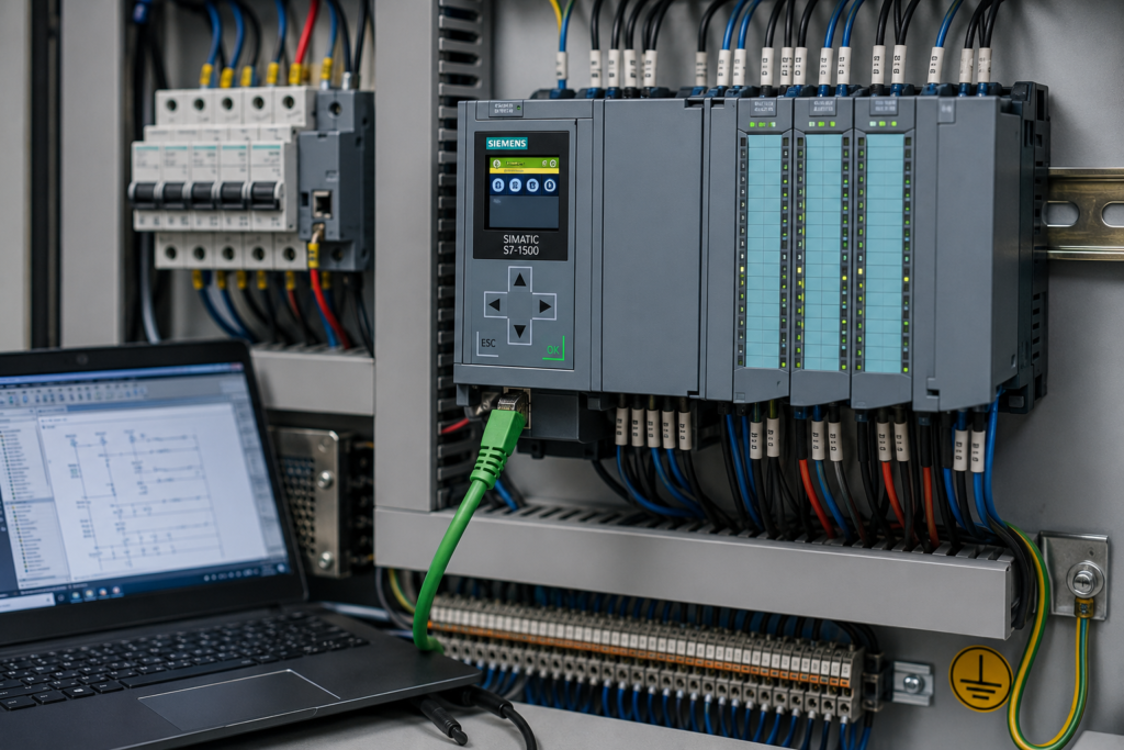
You send a RUN command from TIA Portal, but the Siemens PLC remains in STOP.
Sometimes nothing seems to happen. In other cases, the CPU enters STARTUP briefly, flashes its LEDs, and then returns to STOP. You may also see a red ERROR or SF indicator, a yellow STOP/RUN LED, or a message saying that the operating-mode transition was rejected.
The important point is this:
STOP mode is the symptom, not the diagnosis.
A Siemens CPU may refuse RUN because of:
- an incomplete or inconsistent download;
- incorrect startup settings;
- a hardware-configuration mismatch;
- a missing or defective module;
- a programming error;
- excessive cycle time;
- incompatible firmware;
- a memory-card problem;
- an unfinished safety-program download;
- unstable power;
- internal CPU failure.
Do not repeatedly press RUN or reset the CPU before reading its diagnostics. The diagnostic buffer records mode changes, CPU errors, module faults and many program-related events. Siemens specifically recommends examining the events immediately before the transition to STOP to determine why the CPU stopped.
First Determine Which RUN Problem You Have
There are two common situations, and they point in different directions.
The RUN command is rejected
The CPU stays in STOP and never begins startup.
Possible reasons include:
- physical mode selector remains in STOP;
- user does not have permission to change operating mode;
- no valid program is loaded;
- loading is incomplete;
- safety-program requirements are not satisfied;
- CPU is in a defective state.
The CPU enters STARTUP and returns to STOP
The transition begins, but the CPU discovers a problem while checking hardware or executing startup logic.
Possible reasons include:
- configured module is unavailable;
- hardware does not match the project;
- startup OB contains an error;
- cycle-time limit is exceeded;
- program fault occurs;
- CPU configuration is incompatible;
- a fault requires an error-handling OB that is missing on an older S7-300 or S7-400 system.
Watch the LEDs closely and record whether the CPU:
- remains permanently in STOP;
- briefly enters STARTUP;
- reaches RUN for a moment and then stops;
- shows a red ERROR or SF LED;
- displays a diagnostic message.
That sequence can be more useful than the final STOP indication.
Quick Troubleshooting Table
| What happens | Most likely causes |
|---|---|
| RUN command is unavailable or rejected | Mode selector in STOP, insufficient access rights, CPU protection, incomplete loading or defective CPU |
| CPU enters STARTUP and immediately returns to STOP | Hardware mismatch, missing module, startup-code error or cycle-time fault |
| CPU goes to RUN and later returns to STOP | Runtime programming error, I/O access error, excessive scan time or module failure |
| Problem started after downloading changes | Compile inconsistency, incomplete download, wrong hardware configuration or safety-program mismatch |
| Problem started after replacing the CPU | Wrong CPU order number, firmware mismatch, incompatible memory card or project-device version |
| Red ERROR or SF LED is active | Read the diagnostic buffer; module, configuration, program or hardware fault is present |
| All major CPU LEDs flash continuously | Possible fatal or defective CPU state |
| F-CPU refuses normal operation | Safety program not downloaded consistently, safety signature issue or safety configuration fault |
| CPU starts only after modules are disconnected | Faulty, missing or incorrectly configured local module |
| CPU returns to STOP during machine operation | Runtime error, power interruption, cycle-time overrun or field hardware fault |
Do Not Start With a Factory Reset
A factory reset can erase the program, hardware configuration, retained data and useful evidence without repairing the underlying problem.
Before changing anything:
- Record all CPU and module LEDs.
- Save or photograph messages on the CPU display.
- Go online with the PLC.
- Export or record the diagnostic buffer.
- Compare the online and offline configuration.
- Back up the project and current data where possible.
- Identify what changed immediately before the fault began.
A reset should be a deliberate recovery step—not the opening move.
If the CPU contains the only current copy of a production program, careless resetting can turn one fault into a much larger problem.
Step 1: Read the Diagnostic Buffer
For S7-1200 and S7-1500 systems in TIA Portal, open:
CPU → Online & Diagnostics → Diagnostics → Diagnostic buffer
The buffer records events such as:
- CPU power-up;
- transition to STARTUP;
- transition to RUN;
- transition to STOP;
- CPU errors;
- module errors;
- program errors;
- hardware changes;
- security-related events.
The newest event is displayed first, but the newest event is not necessarily the original cause. Siemens recommends examining the entries immediately before the STOP transition and using the detailed event information or Help on event function to identify the fault.
How to read the sequence
Imagine the buffer contains:
- CPU changed to STOP.
- Peripheral access error.
- PROFINET station failure.
- Remote I/O power loss.
The first event chronologically may be the remote station losing power. The access error and STOP transition are consequences.
Work from the first meaningful incoming error toward the STOP event—not only from the top line downward.
Save the buffer before cycling power
Part of the diagnostics history may survive power interruption, depending on the CPU family, but you should still save the entries before resetting or downloading. Recent S7-1500 diagnostic-buffer entries can be retained through power failure or memory reset.
Step 2: Check the Physical Mode Selector
Before opening the program, look at the CPU itself.
Some Siemens CPUs have a physical operating-mode selector or key switch. Depending on the family, its positions may include:
- RUN;
- STOP;
- RUN-P;
- MRES;
- another model-specific operating position.
This is especially relevant to S7-300, S7-400 and certain S7-1500 CPUs.
If the selector is physically in STOP, a software RUN command may be rejected or unavailable.
Check that:
- the switch is not in STOP;
- it is not between positions;
- a removable key is not restricting operation;
- the front-panel controls are functioning;
- the CPU is not in a memory-reset position.
Do not move a production PLC into RUN until the machine has been made safe. Outputs may energise as soon as program execution begins.
Step 3: Check the CPU Startup Setting
The CPU may be configured to remain in STOP after power-up.
For S7-1200 systems, the startup behaviour can be configured in the CPU properties. Options may include remaining in STOP, starting in RUN or returning to the operating mode that existed before power was removed. If the CPU was previously in STOP and “mode prior to power off” is selected, it can correctly return to STOP after power-up.
In TIA Portal, check the CPU’s startup properties.
Look for settings such as:
- no restart or remain in STOP;
- warm restart to RUN;
- warm restart to previous operating mode;
- permitted comparison between expected and actual hardware;
- startup time limits.
Typical misunderstanding
A technician expects the PLC to restart automatically after an outage, but the project was deliberately configured to remain in STOP.
Nothing is defective.
The CPU is following its configuration.
Before changing this behaviour, consider whether automatic machine restart is safe and permitted. A PLC entering RUN automatically does not necessarily mean motors should start automatically; the control program and safety system must prevent unexpected movement.
Step 4: Compile the Complete Project
A partial or inconsistent project can prevent a correct download and leave the CPU without a usable configuration.
In TIA Portal:
- Select the PLC.
- Choose Compile → Hardware and software.
- Use a full or consistent compile where appropriate.
- Open the compile results.
- Correct every error.
- Review warnings that may affect the hardware or safety program.
- Download the required hardware and software consistently.
TIA Portal disables a consistent download when unresolved compile errors prevent the selected objects from being loaded correctly.
Common compile-related problems
- deleted block still referenced elsewhere;
- changed data type not compiled consistently;
- invalid hardware address;
- technology object with missing configuration;
- safety block changed but not safety-compiled;
- library version mismatch;
- duplicate addresses;
- incorrect device version;
- program block unavailable in the target CPU.
Do not compile only the block you recently edited if hardware, data types or interface definitions also changed.
A clean block can still depend on an inconsistent project.
Step 5: Confirm That the Download Completed
The CPU may remain in STOP because only part of the intended project was loaded.
Possible examples include:
- program blocks downloaded without hardware configuration;
- hardware downloaded without all dependent software;
- download cancelled midway;
- network connection lost during loading;
- safety program omitted;
- wrong CPU selected during download;
- changes downloaded to a spare or simulated device instead of the real PLC.
After loading:
- read the download result carefully;
- confirm there were no failed objects;
- compare online and offline blocks;
- compare device configuration;
- check whether another download is still required;
- verify the correct CPU IP address and identity.
Siemens warns that loading hardware configuration can change machine behaviour and, for some operations, requires the CPU to be placed in STOP.
Do not press RUN immediately after a warning-filled download dialog without understanding what was skipped.
Step 6: Compare Online and Offline Hardware
During startup, the CPU checks its hardware and verifies whether configured modules and parameter sets are available. A missing or mismatched module can therefore prevent normal startup or generate diagnostics.
Possible mismatches include:
- wrong CPU order number;
- wrong CPU firmware version;
- signal module installed in the wrong position;
- missing signal board;
- incorrect ET 200 station;
- different analogue-module variant;
- technology module absent;
- wrong communication processor;
- replacement module with incompatible version.
Check exact order numbers
Two Siemens modules can have nearly identical front labels while differing in:
- channel count;
- input type;
- output type;
- firmware support;
- electrical rating;
- diagnostic capability.
Compare the complete order number—not only the product-family name.
Use hardware detection carefully
TIA Portal can detect installed hardware and help create or compare a configuration. However, do not automatically overwrite a known project with detected hardware without checking the consequences. Siemens provides a hardware-detection function for reading the CPU and installed configuration.
Local modules are especially important
On some CPU families, removing or inserting a configured local module can force the CPU into STOP regardless of whether a pull/plug OB has been programmed.
Inspect the physical rack for:
- poorly seated modules;
- bent connectors;
- missing bus connectors;
- damaged backplane connections;
- incorrect module sequence;
- failed local expansion modules.
Step 7: Check Firmware Compatibility
The CPU configured in the project must be compatible with the actual CPU firmware.
Problems frequently appear after:
- CPU replacement;
- firmware upgrade;
- firmware downgrade;
- project migration;
- importing an old machine backup;
- changing TIA Portal versions.
Check:
- CPU order number;
- online firmware version;
- configured device version;
- TIA Portal support for that firmware;
- module firmware requirements.
For S7-1200 systems, Siemens documents important compatibility limits between early CPU generations and V4 devices. Memory cards and configurations for V1–V3 CPUs are not simply interchangeable with V4 configurations.
Typical replacement mistake
The original machine used an older CPU firmware version.
A new replacement CPU arrives with newer firmware. The old project is downloaded without first replacing or updating the configured device version.
The hardware looks correct, but the CPU configuration is not compatible.
Use TIA Portal’s device-replacement function and follow the supported migration path.
Step 8: Inspect the SIMATIC Memory Card
A memory-card problem can prevent the CPU from loading the intended program or configuration.
Possible causes include:
- card created for an incompatible CPU generation;
- corrupted card contents;
- interrupted firmware update;
- incorrect transfer-card preparation;
- unsupported card;
- card still configured for another function;
- damaged memory card;
- card inserted or removed during an unsuitable operation.
The S7-1200 diagnostic buffer may report an unknown or incompatible CPU configuration when a transfer card or configuration does not match the CPU. Siemens’ documented recovery can include removing the transfer card and repeating the STOP-to-RUN transition after correcting the cause.
What to do
- Read the diagnostic buffer before removing the card.
- Identify whether it is being used as a program card, transfer card or firmware-update card.
- Confirm compatibility with the exact CPU.
- Preserve the existing card contents.
- Use only the manufacturer-supported preparation method.
- Test with a known-good supported card if required.
Do not format or modify the only available card until its contents have been backed up.
Step 9: Check for Startup-Block Errors
During STARTUP, the CPU executes startup organization blocks before entering normal cyclic execution.
A problem in startup logic can prevent successful transition to RUN.
Examples include:
- explicit STOP instruction;
- invalid data access;
- excessive loop;
- unavailable hardware reference;
- communication instruction waiting incorrectly;
- startup code exceeding permitted time;
- poorly initialised data;
- block relying on a device that is not ready.
S7-1200 startup OBs execute during STARTUP before normal time-based program execution begins.
Look for an explicit STP instruction
A programmer may deliberately place an STP or equivalent STOP instruction in:
- startup logic;
- diagnostic OB;
- commissioning code;
- fault-handling routine.
Siemens documents that an STP instruction can be used inside a diagnostic error interrupt OB to intentionally put the CPU into STOP when a diagnostic event occurs.
Search the complete project for:
STP;- stop-control instructions;
- startup fault flags;
- commissioning conditions;
- program branches that deliberately request STOP.
The CPU may not be failing unexpectedly. The user program may be instructing it to stop.
Step 10: Check Maximum Cycle Time
A PLC can return to STOP if its program takes too long to execute.
Possible causes include:
- endless loop;
- very large loop count;
- communication function waiting incorrectly;
- recursive logic;
- excessive block execution;
- program added without reviewing scan time;
- startup routine processing a huge data set;
- interrupt overload.
Siemens CPUs monitor scan-cycle time. When the configured maximum is exceeded, a time-error event is generated and entered in the diagnostic buffer. The CPU’s response depends on the family, configuration and availability of the time-error OB.
Common programming example
WHILE Condition = TRUE DO
    // Condition is never changed
END_WHILE;
The CPU remains trapped inside the loop until its monitoring detects excessive execution time.
How to fix it
- read the exact time-error entry;
- identify the active OB or block;
- monitor scan time;
- check recent loop changes;
- divide large calculations across multiple cycles;
- correct the exit condition;
- review interrupt execution;
- do not simply increase the maximum cycle time without understanding the cause.
Increasing the limit may hide an inefficient or locked program while delaying fault detection.
Step 11: Look for Programming and I/O Access Errors
The CPU may go to STOP because the user program accesses invalid or unavailable data or I/O.
Possible examples include:
- direct peripheral access to a missing module;
- array index outside the allowed range;
- invalid pointer or indirect address;
- inconsistent data block;
- removed remote I/O device;
- wrong logical address;
- failed technology object;
- program-sequence error.
The diagnostic buffer can contain user-program errors, system errors and operating-mode transitions.
If the CPU reaches RUN briefly
Monitor whether STOP occurs when:
- a particular sequence step begins;
- an HMI writes a command;
- a remote station communicates;
- a motion block is executed;
- a specific output or input address is accessed;
- a cyclic interrupt runs for the first time.
A PLC that always stops at the same machine step usually has a repeatable trigger.
Use:
- diagnostic-buffer timestamps;
- block call stack where available;
- online monitoring;
- traces;
- cross-references;
- program-status information.
Step 12: Understand Error OBs on S7-300 and S7-400
Older S7-300 and S7-400 CPUs can enter STOP when certain errors occur and the corresponding organization block is not loaded or cannot be executed.
Siemens lists STOP events caused by:
- programming errors;
- I/O access errors;
- time errors;
- module removal or insertion;
- rack failure;
- communication errors;
- program-sequence errors;
- hardware interrupts.
The diagnostic event may explicitly state that the required OB was not loaded or was not possible.
A classic example is diagnostic interrupt OB82. On applicable S7-300 and S7-400 CPUs, Siemens states that the CPU changes to STOP if OB82 is required but has not been programmed.
Other commonly relevant error OBs may include:
- OB80 — time error;
- OB82 — diagnostic interrupt;
- OB83 — module pull/plug;
- OB85 — program-execution error;
- OB86 — rack or station failure;
- OB121 — programming error;
- OB122 — I/O access error.
Do not add empty error OBs merely to keep the CPU running.
An error OB can prevent a STOP transition, but the program must still handle the failed hardware or invalid data safely. Keeping the CPU in RUN while using unavailable process values can be more dangerous than allowing it to stop.
Step 13: Check Distributed I/O and PROFINET Devices
A missing remote station does not always force every Siemens CPU into STOP, but the program’s reaction to the missing device can.
Possible causes include:
- ET 200 station has no power;
- PROFINET cable disconnected;
- wrong device name;
- duplicate IP address;
- network switch failure;
- replacement device not assigned correctly;
- remote module arrangement differs from the project;
- program directly accesses unavailable I/O.
Check:
- PROFINET link LEDs;
- remote-station power;
- device name;
- accessible devices;
- network diagnostics;
- module status;
- hardware identifiers;
- related entries in the diagnostic buffer.
The CPU may first report a station failure, then a peripheral-access error, and finally STOP because the program lacks suitable error handling.
Repair the first fault in the sequence.
Step 14: Check the 24V Power Supply
An unstable supply can cause repeated startup attempts, module failures or unexpected STOP transitions.
Possible problems include:
- undersized power supply;
- failing power supply;
- loose +24V terminal;
- loose 0V connection;
- voltage drop during output startup;
- shorted field circuit;
- overloaded sensor supply;
- high-resistance fuse or electronic protection channel;
- poor terminal jumper.
Measure voltage:
- at the power-supply output;
- at the CPU terminals;
- during power-up;
- while modules and field loads energise;
- during the exact moment the CPU returns to STOP.
A normal reading while the machine is idle does not rule out a short voltage dip.
Use a recording meter or oscilloscope if the interruption is too brief for an ordinary multimeter.
Also check whether expansion modules have separate load-voltage supplies. The CPU may be powered while one required module is not ready for operation.
Step 15: Check CPU Access Protection
The person attempting to change the operating mode may not have the required access rights.
Modern Siemens projects can use:
- access levels;
- passwords;
- user management;
- protected PLC configuration;
- communication restrictions;
- security policies.
Symptoms can include:
- RUN/STOP command unavailable;
- operation rejected;
- online functions restricted;
- download refused;
- password prompt;
- insufficient-access message.
Confirm that:
- you are connected to the intended CPU;
- the correct user account is active;
- required credentials are available;
- the project protection settings match the online device;
- another engineering session is not controlling access.
Do not circumvent protection on an operational machine. Determine who is authorised to change the CPU state.
Step 16: Check Fail-Safe CPU Requirements
An F-CPU adds a safety program and safety-related configuration to the standard PLC project.
A failed or incomplete safety download can leave the CPU or safety program in an unexpected state.
Check:
- safety program compiled consistently;
- collective F-signature;
- F-runtime groups;
- safety password;
- F-I/O addresses;
- safety administration status;
- whether a normal and safety download both completed;
- passivation or configuration errors.
For S7-1200 and S7-1500 F-CPUs, Siemens documents cases where an interrupted or unsuitable RUN-mode safety download must be recovered by switching the F-CPU to STOP and downloading a consistently compiled safety program.
Do not clear, bypass or modify safety logic merely to force the PLC into operation.
The machine’s safety validation may need to be repeated after safety-program changes.
Step 17: Check for Defective Hardware
Hardware failure becomes more likely when:
- the CPU cannot be reached online;
- all power supplies are correct;
- the correct project and firmware are confirmed;
- the CPU shows a permanent defective indication;
- several LEDs flash continuously;
- fault remains with expansion modules removed according to the manual;
- known-good memory and power supplies do not help;
- the diagnostic buffer reports internal or fatal errors.
For S7-1200 CPUs, Siemens documents a defective mode in which the STOP/RUN, ERROR and MAINT LEDs flash continuously after a fatal firmware-detected error. In that condition, the normal user program and hardware configuration are not loaded.
For S7-1500 CPUs that do not complete startup after diagnostics have been collected, Siemens guidance may lead to CPU replacement or support analysis.
Before replacing the CPU
Confirm:
- correct supply voltage;
- correct polarity;
- no overvoltage or surge damage;
- no conductive contamination;
- no damaged backplane;
- no faulty module pulling down the rack;
- correct firmware;
- supported memory card;
- compatible project.
A replacement CPU connected to the same defective supply or backplane may fail as well.
Symptom-Based Diagnosis
CPU stays in STOP after power-up
Check:
- Startup-after-power-on setting.
- Physical mode selector.
- Diagnostic buffer.
- Memory card.
- Hardware mismatch.
- Power supply.
- Firmware compatibility.
CPU enters STARTUP and goes back to STOP
Check:
- First diagnostic event during STARTUP.
- Startup OBs.
- Missing local modules.
- Hardware configuration.
- Maximum startup or cycle time.
- Explicit STP instruction.
- Safety-program consistency.
CPU goes into RUN and stops after a few seconds
Check:
- Runtime program error.
- Peripheral I/O access.
- cyclic interrupt.
- communication block.
- remote I/O station.
- scan-cycle time.
- first active machine-sequence step.
CPU stopped after replacing a module
Check:
- Complete order number.
- Module slot.
- Firmware version.
- configured module variant.
- bus connector.
- load voltage.
- hardware download.
CPU stopped after replacing the CPU
Check:
- CPU order number.
- Firmware.
- TIA Portal device version.
- memory-card compatibility.
- project protection.
- IP address and PROFINET name.
- complete hardware-and-software download.
CPU stopped after program changes
Check:
- Compile errors.
- incomplete download.
- changed DB interfaces.
- invalid addresses.
- loops and scan time.
- startup logic.
- safety signature.
- online/offline differences.
A Reliable Step-by-Step Recovery Procedure
Step 1: Make the machine safe
Do not place the CPU in RUN while personnel are inside hazardous areas or while actuators could move unexpectedly.
Step 2: Record all indications
Photograph:
- CPU LEDs;
- module LEDs;
- CPU display;
- HMI alarms.
Step 3: Go online without downloading
Read the real CPU first.
Step 4: Export the diagnostic buffer
Preserve the evidence before power cycling or resetting.
Step 5: Find the STOP transition
Read the events immediately before it.
Step 6: Check the operating-mode selector
Confirm the hardware control permits RUN.
Step 7: Compare online and offline hardware
Check CPU, modules, slots and firmware.
Step 8: Compile the complete project
Correct all errors.
Step 9: Check startup settings and startup OBs
Look for deliberate STOP commands, invalid access and excessive processing.
Step 10: Verify power and module readiness
Measure the supply under load.
Step 11: Download consistently
Load the correct hardware, software and safety program.
Step 12: Issue RUN with the process controlled
Monitor the diagnostic buffer during the transition.
Step 13: If it returns to STOP, record the new event
Do not repeat the same action without changing or learning anything.
Step 14: Test the complete machine sequence
A CPU remaining in RUN while idle does not prove that the program is healthy under real process conditions.
What Not to Do
Avoid these common mistakes:
- Do not factory-reset the CPU first.
- Do not repeatedly command RUN without reading diagnostics.
- Do not download an old project blindly.
- Do not ignore the exact CPU firmware.
- Do not replace modules based only on a red LED.
- Do not add empty error OBs without analysing the fault.
- Do not increase maximum cycle time blindly.
- Do not bypass safety-program requirements.
- Do not assume the CPU is defective before checking power and configuration.
- Do not place a machine into RUN without controlling hazardous outputs.
- Do not remove the memory card before recording its role and contents.
- Do not use online/offline equality as the only proof that hardware is healthy.
A green RUN LED is not the objective by itself.
The objective is a correctly configured PLC executing a safe and valid program.
Why a Siemens PLC Will Not Go Into RUN Mode
A Siemens PLC remains in STOP because the CPU cannot—or is not permitted to—complete the transition into normal program execution.
The most common causes are:
- startup configured to remain in STOP;
- physical selector in STOP;
- unresolved compile errors;
- incomplete download;
- hardware mismatch;
- missing or defective module;
- firmware incompatibility;
- startup-program error;
- excessive cycle time;
- invalid I/O access;
- missing error OB on an S7-300 or S7-400;
- memory-card problem;
- inconsistent safety program;
- unstable 24V supply;
- defective CPU hardware.
Begin with the diagnostic buffer.
Find the first meaningful event before the STOP transition, confirm the actual hardware and firmware, and then correct the specific problem before trying RUN again.
The RUN button is easy to find.
The reason the PLC refuses it is almost always written somewhere in the diagnostics.