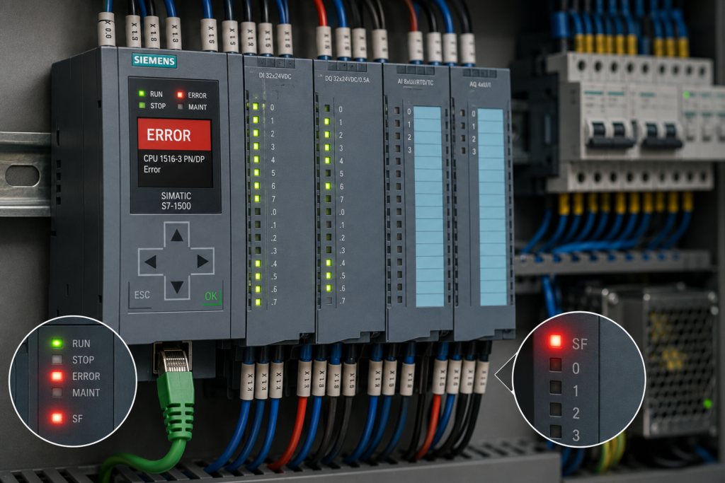
A red light on a Siemens PLC does not automatically mean the CPU has failed.
It means the control system has detected a fault that needs to be identified.
Depending on the Siemens PLC family, the red indication may be labelled:
- ERROR on many S7-1200 and S7-1500 CPUs;
- SF for System Fault or group fault on many S7-300, S7-400 and distributed-I/O devices;
- DIAG on individual signal and interface modules;
- BF or BUSF when the problem is specifically related to a communication network.
The red CPU LED is usually a summary indication. The actual problem may be several metres away in a remote I/O cabinet, field sensor, output cable or missing PROFINET device.
The most common causes include:
- faulty I/O module;
- incorrect hardware configuration;
- missing PROFINET device;
- channel-level short circuit;
- missing or unstable power supply.
The correct troubleshooting method is therefore:
- Identify which LED is red.
- Determine whether it is flashing or continuously lit.
- Open the Siemens diagnostics.
- Locate the exact device, module and channel reporting the fault.
- Correct the physical or configuration problem.
- Confirm that the diagnostic event changes from incoming to outgoing.
Do not replace the CPU simply because it is the component displaying the red light.
The CPU may only be the messenger.
ERROR LED vs SF LED
The terminology depends on the PLC generation.
S7-1200 and S7-1500
Modern Siemens CPUs commonly use a red ERROR LED.
On an S7-1200, a flashing red ERROR LED can indicate:
- internal CPU error;
- SIMATIC memory-card problem;
- hardware-configuration error;
- mismatch between configured and installed modules.
A solid red ERROR indication on an S7-1200 can indicate defective hardware, while all major LEDs flashing can indicate that the firmware has detected a defective state.
S7-1500 CPUs also use a red ERROR LED together with RUN/STOP and MAINT indications. Siemens advises using the CPU diagnostic buffer for the detailed explanation when the CPU detects an error state.
S7-300 and S7-400
Older systems frequently use an SF LED.
SF is a group-fault indication rather than one specific diagnosis. Siemens identifies SF as the group-error LED, while some CPUs or modules also provide separate indications such as INTF for internal fault, EXTF for external fault and BUSF for bus faults.
I/O and communication modules
Individual modules may use:
- DIAG;
- ERROR;
- SF;
- BF;
- channel-error LEDs;
- power-status LEDs.
A red CPU ERROR LED and a red channel LED do not have the same meaning.
The CPU LED says that a diagnostic exists somewhere in the system.
The module and channel LEDs help show where.
Quick Troubleshooting Table
| LED condition | Most likely meaning |
|---|---|
| CPU ERROR flashing red | Active diagnostic, configuration mismatch, memory-card problem, module fault or communication problem |
| CPU ERROR solid red | Possible defective CPU hardware on supported S7-1200 models |
| SF LED red | Group fault caused by an internal or external module/system error |
| Module DIAG flashing red | Module or channel diagnostic is active |
| One channel LED red | Fault associated with that specific input, output or sensor-supply channel |
| BF or BUSF red/flashing | PROFIBUS or PROFINET communication problem |
| Remote station ERROR red and LINK off | No physical Ethernet connection or missing network link |
| Module DIAG red with power LED off | Missing or insufficient module or load voltage |
| ERROR and MAINT show a coded flashing pattern | Configuration or station error requiring model-specific LED interpretation |
| CPU RUN green but ERROR red | CPU may still be executing the program while a hardware, communication or channel diagnostic remains active |
Can the PLC Stay in RUN With a Red ERROR LED?
Yes.
A red ERROR or SF LED does not always mean the CPU is in STOP.
The PLC may remain in RUN while reporting:
- failed remote I/O;
- missing sensor supply;
- wire break;
- channel short circuit;
- incorrect module configuration;
- unavailable PROFINET device.
Whether the CPU continues running depends on:
- CPU family;
- fault type;
- configured reaction;
- available error-handling OBs;
- how the user program accesses the failed hardware.
Always check the RUN/STOP LED separately.
A green RUN LED means the processor is executing the program. It does not mean every configured device and I/O channel is healthy.
Start With the Diagnostic Buffer
For S7-1200 and S7-1500 systems, connect with TIA Portal and open:
Online & Diagnostics → Diagnostics → Diagnostic buffer
The buffer provides the most useful starting information:
- event description;
- affected module;
- rack and slot;
- hardware identifier;
- whether the event is incoming or outgoing;
- date and time;
- recommended diagnostic help.
Siemens recommends evaluating the events immediately before a CPU transition to STOP and using the detailed event information to narrow the cause. The same approach is useful even when the CPU remains in RUN with the ERROR LED active.
Incoming and outgoing events
An incoming event means the fault appeared.
An outgoing event means the system no longer detects it.
For example:
- Incoming: load voltage missing.
- Incoming: output module unavailable.
- Outgoing: load voltage missing.
- Outgoing: output module unavailable.
If the physical problem has been repaired but no outgoing event appears, the fault may still be present, the module may need reparameterisation, or the diagnostic may require acknowledgment.
Read the first cause, not only the last result
A fault sequence might show:
- Remote ET 200 station lost power.
- PROFINET station unavailable.
- Peripheral access error.
- CPU ERROR LED activated.
The remote power loss is the original cause.
The later events are consequences.
Use the Online Device View
Open the PLC’s online device configuration in TIA Portal.
The hardware view can show:
- green check mark for a healthy module;
- red fault symbol;
- grey or unavailable device;
- configuration mismatch;
- missing module;
- channel diagnostic;
- maintenance request.
Expand the hardware tree until you reach the lowest level that contains the red diagnostic icon.
Do not stop at the CPU if the diagnostic tree identifies:
- rack;
- interface module;
- signal module;
- submodule;
- individual channel.
The closer you get to the field level, the less guesswork remains.
1. Faulty I/O Module
A defective or non-operational I/O module can activate the CPU ERROR or SF indication.
The module may have failed completely, or it may be unavailable because of:
- internal electronics failure;
- backplane-bus problem;
- missing supply;
- incorrect seating;
- damaged connector;
- incompatible firmware;
- severe channel fault.
On S7-1200 signal modules, Siemens states that a red DIAG indication means the module is defective or non-operational. Individual analogue channels may also show red when that specific input or output has an error.
Signs of a faulty module
- Red DIAG or SF LED remains active.
- Module is shown as unavailable online.
- All channels on the module stop updating.
- Fault remains after field wiring is disconnected correctly.
- Module is unusually hot.
- Module has visible or burnt damage.
- Fault follows the module when exchanged with an identical known-good unit.
- Diagnostics report internal module error.
Before replacing the module
Check the simpler external causes first:
- Verify module supply voltage.
- Inspect the backplane or bus connector.
- Confirm the module is fully seated.
- Check the front connector.
- Disconnect faulty field circuits safely.
- Confirm the module order number.
- Check the configured firmware or hardware version.
- Read the module’s own diagnostic details.
A signal module may appear defective when its load voltage is simply missing.
Check the exact order number
Do not compare only the description printed in large letters.
Two modules may both be described as “16-channel digital input” while differing in:
- input voltage;
- high-speed capability;
- source or sink wiring;
- diagnostics;
- firmware;
- channel arrangement;
- hardware revision.
Compare the complete Siemens order number in the project with the number on the installed module.
Replace only after configuration is verified
If an incorrect module is installed, replacing it with another identical incorrect module will not clear the diagnostic.
The installed device must match the project—or the project must be deliberately updated to match the approved hardware.
2. Incorrect Hardware Configuration
A hardware mismatch is a common reason for a flashing red ERROR LED after:
- downloading a project;
- replacing a CPU;
- replacing an I/O module;
- adding expansion hardware;
- migrating to another TIA Portal version;
- upgrading firmware.
Siemens specifically lists mismatched modules as one reason the S7-1200 ERROR LED flashes red.
Typical configuration mismatches
- Wrong CPU order number.
- Wrong CPU firmware version.
- Incorrect signal-module variant.
- Module installed in the wrong slot.
- Module missing from the physical rack.
- Extra module installed but not configured.
- Incorrect ET 200 module sequence.
- Signal board configured but not installed.
- Wrong submodule selected.
- Device replacement completed physically but not in TIA Portal.
Example
The project expects:
SM 1231 AI 4-channel analogue input
The installed module is:
SM 1231 RTD temperature module
The housings may look similar, but they are not interchangeable.
The CPU compares the configured hardware with the detected hardware and reports the difference.
Step-by-step configuration check
Step 1: Go online
Open the device configuration and compare online and offline states.
Step 2: Read the diagnostic text
Look for messages such as:
- configured module not found;
- module type mismatch;
- wrong module;
- configuration differs;
- submodule unavailable;
- invalid configuration.
Step 3: Check every slot
Compare:
- rack number;
- slot number;
- module order number;
- firmware version;
- submodule selection.
Step 4: Inspect the physical rack
Confirm the module has not been inserted one position away from its configured slot.
Step 5: Compile hardware and software
Perform a consistent compile and review all errors.
Step 6: Download the correct hardware configuration
Make sure the machine is in a safe condition before loading hardware changes.
Step 7: Verify the outgoing diagnostic
The red LED may not clear until the CPU has accepted the corrected configuration and the module has restarted successfully.
Invalid distributed-I/O configuration
ET 200 interface modules can indicate configuration problems through ERROR and MAINT LEDs. Siemens lists examples such as multiple removed I/O modules, a missing server module and a backplane-bus interruption or short circuit.
This means a red light on an ET 200 station may be caused by the station structure rather than the PROFINET cable itself.
Inspect the complete station from the interface module to the final server or terminating module.
3. Missing PROFINET Device
A missing PROFINET device is another common reason for a red ERROR, SF or bus-fault indication.
Typical affected devices include:
- ET 200 remote I/O;
- VFD;
- servo drive;
- HMI;
- valve manifold;
- vision system;
- robot controller;
- another PLC operating as an I-device.
The CPU expects cyclic communication with the configured device. When communication fails, system diagnostics report that the device or submodule is unavailable.
Common reasons a PROFINET device is missing
- Device has no power.
- Ethernet cable is disconnected.
- Cable or connector is damaged.
- Network switch has failed.
- Device name is missing or incorrect.
- IP configuration is wrong.
- Duplicate IP address exists.
- Wrong replacement device was installed.
- Device is configured on the wrong PLC interface.
- Device is disabled or not commissioned.
- PROFINET interface has no physical link.
An interface-module LINK LED that is off indicates that there is no Ethernet connection to a communication partner. Siemens recommends checking the cable to the switch or IO controller.
Physical link vs PROFINET communication
A green LINK LED proves that an Ethernet link exists.
It does not prove that PROFINET data exchange is working.
A device may have a physical link but still be unavailable because of:
- wrong PROFINET device name;
- incorrect configuration;
- incompatible module layout;
- controller assignment error;
- device startup failure.
LINK off
Check:
- cable;
- switch port;
- connector;
- device power;
- correct Ethernet port.
LINK on but device missing
Check:
- PROFINET name;
- IP address;
- device assignment;
- online accessible devices;
- hardware configuration;
- station diagnostics.
Check the device name
PROFINET IO commonly identifies a configured device using its assigned device name.
A replacement ET 200 interface or drive may have the correct IP address yet remain unavailable because the required PROFINET name has not been assigned.
In TIA Portal:
- Open Online access or Accessible devices.
- Identify the device by MAC address.
- Compare its device name with the project.
- Assign the correct name where authorised.
- Confirm that cyclic communication begins.
PLC configured as an I-device
An S7-1500 CPU configured as an I-device can show an ERROR indication if its higher-level IO controller cannot be reached. Siemens documents that the I-device function can be disabled programmatically in applications where the higher-level controller is intentionally absent.
Do not disable a required I-device connection simply to remove the red LED.
First determine whether the missing controller is a valid operating condition or a real communication fault.
4. Channel-Level Short Circuit
A single field-wiring fault can activate the module DIAG LED and, through system diagnostics, cause the PLC’s red summary indication.
This is especially common with:
- digital-output channels;
- protected sensor supplies;
- fail-safe channels;
- analogue transmitter supplies;
- shorted field cables.
Not every Siemens module detects every type of short circuit. Channel diagnostics must be supported by the hardware and, in many cases, enabled in the module parameters.
Typical short-circuit locations
- Output conductor shorted to 0V.
- Output conductor shorted to L+.
- Sensor-supply wire shorted to ground.
- Crushed field cable.
- Damaged solenoid coil.
- Incorrectly wired valve plug.
- Water inside a junction box.
- Loose conductor strand touching an adjacent terminal.
- Excessive load current on an output channel.
Some Siemens modules generate a diagnostic alarm and flash their DIAG LED when a supported short-circuit condition is detected. One documented S7-1500 input module, for example, reports a short circuit on the 24V sensor-supply line and identifies correcting the process wiring as the remedy.
Use the channel LED
If the module has individual fault LEDs, identify:
- which channel is red;
- whether all channels are affected;
- whether the DIAG LED is red;
- whether the power LED is present.
On supported S7-1200 modules, the red DIAG LED acts as a summary indication for module and enabled channel diagnostics, while the affected channel may also flash red.
Step-by-step short-circuit isolation
Step 1: Record the channel
Write down the exact module and channel before disconnecting anything.
Step 2: Place the process in a safe condition
A shorted output may control a valve, brake, contactor or actuator.
Step 3: Isolate power correctly
Follow the site’s lockout procedure.
Step 4: Disconnect the field load
Remove the field circuit from the affected output or sensor supply according to the wiring diagram.
Step 5: Restore power for an approved test
If the diagnostic clears with the field circuit removed, the fault is probably in:
- field cable;
- connected device;
- junction box;
- plug;
- load.
If the diagnostic remains with the field wiring correctly removed, suspect:
- damaged channel;
- wrong configuration;
- internal module fault.
Step 6: Divide the circuit
Disconnect branches systematically rather than replacing every connected component.
Step 7: Measure the load
Check coil resistance, cable insulation and conductor continuity using equipment suitable for the circuit.
Do not perform insulation-resistance testing through connected PLC electronics.
Short circuit vs overload
An output may report:
- short circuit;
- overload;
- overtemperature;
- actuator supply fault.
The external symptom can be similar: the output switches off and the channel LED turns red.
Read the complete event text before deciding whether the problem is a direct short or simply a load exceeding the channel rating.
5. Power-Supply Problem
A Siemens system can contain several different power supplies:
- CPU electronics supply;
- I/O bus supply;
- sensor supply;
- output load voltage;
- remote-station supply;
- isolated analogue supply;
- network-device supply.
The CPU may be powered and running while one field-side supply is missing.
That missing supply can create a red module or CPU diagnostic.
CPU supply missing
If the CPU itself has no or insufficient supply, its LEDs may all be off rather than showing an ordinary red fault. Siemens describes all CPU status LEDs off as a possible missing or insufficient CPU supply condition on supported S7-1500 hardware.
Check:
- +24V at the CPU terminals;
- 0V return;
- fuse or electronic protection;
- polarity;
- loose connector;
- power-supply output.
Module load voltage missing
An I/O module may receive backplane communication power while its field-side L+ supply is absent.
In that situation:
- the module remains visible to the PLC;
- its DIAG LED may flash red;
- outputs may not operate;
- inputs or sensor supply may be unavailable;
- the CPU may report a system diagnostic.
Siemens documents a “load voltage missing” diagnostic when the L+ supply to a module or channel is absent.
On supported S7-1200 digital modules, a field-side power fault with diagnostics enabled can make the module DIAG LED flash red while the channel LEDs remain off.
Remote I/O power missing
An ET 200 station without electronic supply may disappear from PROFINET entirely.
The CPU may then report:
- station not reachable;
- device failure;
- submodule unavailable;
- I/O access problem.
Check power locally at the remote station—not only in the main PLC cabinet.
Voltage present but too low
A multimeter may show 24V while the system is idle, but voltage may collapse when outputs energise.
Possible causes include:
- undersized power supply;
- shorted field circuit;
- overloaded output group;
- loose terminal;
- long cable;
- high-resistance fuse;
- defective electronic circuit protector.
Measure voltage:
- at the power-supply output;
- at the CPU;
- at the affected module;
- during output switching;
- during the moment the diagnostic appears.
A recording meter or oscilloscope may be needed for brief dips.
Check the 0V path
A broken 0V return can create confusing symptoms:
- voltage appears present relative to earth;
- sensors illuminate;
- inputs do not switch correctly;
- modules reset intermittently;
- diagnostics appear and disappear.
Measure between the actual L+ and M terminals used by the device.
Do not rely only on measurements to protective earth.
A Complete Step-by-Step Diagnostic Procedure
Step 1: Identify every red LED
Check:
- CPU ERROR or SF;
- BF or BUSF;
- module DIAG;
- channel LEDs;
- power LEDs;
- LINK LEDs;
- MAINT.
Write down whether each LED is:
- off;
- continuously lit;
- flashing slowly;
- flashing rapidly;
- alternating with another LED.
Step 2: Check CPU operating mode
Is the CPU:
- in RUN;
- in STOP;
- entering STARTUP repeatedly;
- defective?
A red fault with RUN green requires a different response from a CPU that has entered STOP.
Step 3: Go online without downloading
Do not overwrite the controller before reading its current diagnostics.
Step 4: Open the diagnostic buffer
Find the newest incoming event and the first event in the fault chain.
Step 5: Open the online hardware view
Expand the red diagnostic symbols until you reach the affected:
- device;
- rack;
- module;
- submodule;
- channel.
Step 6: Check power first
Verify:
- CPU supply;
- remote-station supply;
- module L+;
- sensor supply;
- output load supply.
Step 7: Check communication
For PROFINET faults, inspect:
- LINK LEDs;
- cables;
- switch ports;
- device name;
- IP settings;
- controller assignment.
Step 8: Compare hardware configuration
Check the complete order number, slot and firmware.
Step 9: Inspect field wiring
For channel faults, isolate the connected sensor, actuator or cable.
Step 10: Correct the original cause
Do not merely acknowledge the diagnostic.
Step 11: Confirm the outgoing event
The module should return to a healthy online state.
Step 12: Test the process
Confirm that:
- inputs change correctly;
- outputs operate correctly;
- remote devices exchange data;
- fault does not return;
- no safety function has been affected.
Symptom-Based Troubleshooting
ERROR LED appeared after replacing a module
Check:
- full order number;
- correct slot;
- front connector;
- bus connector;
- firmware;
- hardware download;
- module power.
ERROR LED appeared after maintenance work
Check:
- disconnected PROFINET cable;
- missing terminal jumper;
- field supply switched off;
- module not fully seated;
- damaged output cable;
- wrong replacement sensor.
ERROR LED appears when one output turns on
Suspect:
- shorted output;
- overloaded coil;
- damaged solenoid;
- missing load supply;
- voltage collapse.
ERROR LED appears after a remote cabinet is powered down
Suspect:
- expected PROFINET station failure;
- missing ET 200 power;
- network switch power loss;
- direct I/O access to unavailable channels.
ERROR LED is on, but everything appears to work
Check for:
- unused configured device;
- disabled or spare channel with diagnostics enabled;
- old incoming diagnostic not yet cleared;
- channel wire-break monitoring on an unconnected input;
- redundant or optional station unavailable;
- maintenance request.
ERROR LED flashes after downloading hardware
Suspect:
- hardware mismatch;
- incompatible CPU or module version;
- incomplete hardware configuration;
- missing configured module;
- invalid station layout.
What Not to Do
Avoid these common mistakes:
- Do not factory-reset the CPU first.
- Do not replace the CPU because its ERROR LED is red.
- Do not download an old project before reading diagnostics.
- Do not disable all module diagnostics to make the light disappear.
- Do not assign random PROFINET names.
- Do not replace modules without comparing order numbers.
- Do not bypass fuses or electronic protection channels.
- Do not assume 24V measured without load proves the supply is healthy.
- Do not reconnect a shorted output repeatedly.
- Do not ignore a red channel LED because the CPU remains in RUN.
- Do not treat the LED as a safety indication.
A green PLC does not necessarily mean a healthy machine.
A red PLC does not necessarily mean a failed CPU.
The diagnostic details decide.
Why the Siemens ERROR or SF LED Is Red
A red Siemens ERROR or SF LED is a summary warning that the PLC system has detected a hardware, configuration, communication, channel or supply fault.
The most likely causes are:
- faulty or unavailable I/O module;
- mismatch between installed and configured hardware;
- missing PROFINET device;
- short circuit or overload on an I/O channel;
- missing CPU, module, sensor or load voltage.
Begin in TIA Portal with the diagnostic buffer and online device view.
Then follow the red diagnostic symbol downward:
CPU → network → station → module → channel → field device
That sequence is much faster than replacing components at random.
The red light tells you that something is wrong.
The diagnostic buffer tells you what.