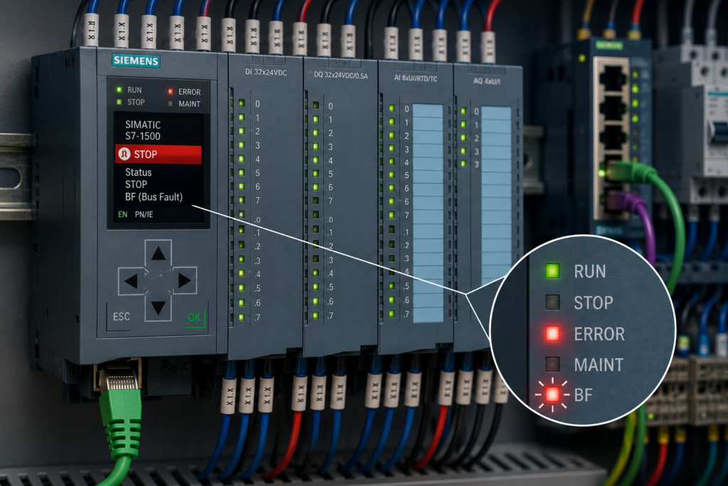
A flashing BF, BUSF or Bus Fault LED on Siemens equipment means that the device is not exchanging communication data correctly.
The fault may appear on:
- a Siemens CPU;
- ET 200 remote I/O;
- a PROFINET interface module;
- a PROFIBUS communication module;
- a SINAMICS drive;
- another Siemens networked device.
The connected equipment may still have power. Its Ethernet LINK LED may even be green. However, the PLC and field device are not completing the expected cyclic communication.
The most common causes are:
- disconnected network cable;
- incorrect PROFINET device name;
- wrong IP address or subnet;
- missing or unpowered remote I/O;
- PROFIBUS address mismatch;
- damaged connector, cable or termination.
A bus fault is not automatically a CPU failure.
In many cases, the CPU is working correctly and reporting that a configured remote device cannot be reached.
What Does the BF LED Mean?
BF normally stands for Bus Fault.
It tells you that communication between configured network devices is missing, interrupted or inconsistent.
On a PROFINET device, the BF LED may indicate:
- no physical Ethernet link;
- no data exchange with the IO controller;
- incorrect PROFINET device name;
- configuration or parameterisation error.
For example, Siemens documents that some ET 200 PROFINET devices show BF continuously when they are not connected to an Ethernet switch, while flashing BF indicates faulty or absent data exchange with the IO controller. The exact solid and flashing patterns vary between device families, so the model-specific manual remains important.
On a PROFIBUS device, BF usually indicates that the DP master and slave are not exchanging data correctly.
Possible reasons include:
- cable disconnection;
- wrong station address;
- duplicate address;
- incorrect baud-rate or bus configuration;
- reversed bus conductors;
- missing termination;
- damaged connector.
The BF LED shows that communication is unhealthy.
It does not identify the cause by itself.
BF, SF and ERROR Are Different Indicators
Siemens devices may show several red LEDs at the same time.
BF or BUSF
Indicates a communication-bus problem.
Check:
- PROFINET;
- PROFIBUS;
- network cables;
- addresses;
- device names;
- remote devices.
SF
Indicates a system or group fault.
The cause may be:
- missing module;
- hardware mismatch;
- channel diagnostic;
- remote station failure;
- programming or I/O access fault.
ERROR
Common on newer S7-1200 and S7-1500 systems.
It indicates that a CPU, module or configured device has reported a diagnostic.
A missing remote station may therefore produce:
- BF on the communication interface;
- ERROR or SF on the CPU;
- DIAG on the remote I/O station.
Do not troubleshoot each LED as an unrelated fault. They may all come from the same missing device.
Quick Troubleshooting Table
| LED and network condition | Most likely causes |
|---|---|
| BF red and LINK LED off | Disconnected cable, damaged connector, unpowered switch or no device power |
| BF flashing and LINK LED on | Incorrect PROFINET name, configuration mismatch, IO controller unavailable or no cyclic data exchange |
| BF appeared after replacing an ET 200 interface | Device name not assigned, wrong IP configuration or wrong device variant |
| BF affects one remote station only | Local station power, cable, connector, name, address or hardware problem |
| BF affects every remote station | PLC interface, main switch, trunk cable, master configuration or common power problem |
| PROFIBUS BF flashes on one slave | Wrong address, damaged connector, missing power or incorrect station configuration |
| Several PROFIBUS slaves fail after one point | Broken cable, connector fault or termination enabled in the middle of the segment |
| Entire PROFIBUS segment fails intermittently | Incorrect termination, loose shield, damaged cable, duplicate address or electrical interference |
| BF appears only when machinery moves | Flexible cable damage, loose connector, vibration or poor shield connection |
| BF appears after a hardware download | Network configuration mismatch, wrong assigned device or missing configured station |
Start With TIA Portal Diagnostics
Before changing addresses or replacing cables, read the PLC diagnostics.
For S7-1200 and S7-1500 systems:
- Go online with the CPU.
- Open Online & Diagnostics.
- Open the Diagnostic buffer.
- Find the incoming station or communication fault.
- Open the online device view.
- Expand the hardware tree until the missing device is identified.
The diagnostic message may contain:
- device name;
- IP address;
- rack and slot;
- hardware identifier;
- interface;
- station failure;
- submodule unavailable;
- incoming or outgoing event.
This is much faster than checking every network cable in the factory.
Look for the first event
A fault sequence may show:
- ET 200 station power lost.
- PROFINET device unavailable.
- Peripheral access error.
- CPU ERROR LED activated.
The first event is the useful one.
The later events describe the consequences.
Identify Whether the Network Is PROFINET or PROFIBUS
Do not begin troubleshooting until you know which bus is affected.
PROFINET
Usually uses industrial Ethernet through:
- RJ45 connectors;
- M12 Ethernet connectors;
- managed or unmanaged Ethernet switches;
- standard or industrial Ethernet cable.
PROFINET devices use a device name and IP address.
PROFIBUS DP
Usually uses:
- purple RS-485 cable;
- 9-pin D-sub bus connectors;
- station-address switches or software addresses;
- termination switches at the ends of the segment.
PROFIBUS is not Ethernet.
Changing an IP address will not repair a PROFIBUS BF fault.
Likewise, adjusting a PROFIBUS termination switch will not fix an incorrectly named PROFINET device.
PROFINET Bus Fault Troubleshooting
1. Disconnected Network Cable
A disconnected or damaged Ethernet cable is the simplest cause of a PROFINET bus fault.
Check the LINK LEDs on:
- CPU Ethernet port;
- network switch;
- remote I/O interface;
- drive or field device.
A Siemens PROFINET interface with no physical connection normally shows no LINK indication. Siemens device documentation recommends checking the cable to the switch or IO controller when no Ethernet connection is detected.
LINK LED Off
Suspect:
- cable unplugged;
- broken conductor;
- damaged RJ45 plug;
- damaged M12 connector;
- wrong switch port;
- unpowered switch;
- unpowered remote station;
- failed Ethernet port.
Step-by-step cable check
- Confirm that the remote device has power.
- Inspect both cable ends.
- Confirm the plugs are fully inserted.
- Check the switch-port LINK LED.
- Test with a known-good cable where practical.
- Try another approved switch port.
- Inspect the cable along moving or exposed sections.
- Check the device’s Ethernet port for damage.
Do not assume the cable is healthy because the outer jacket looks intact.
Industrial Ethernet conductors can break internally near:
- connector strain relief;
- cabinet door;
- drag chain;
- robot movement point;
- sharp bend;
- poorly fitted field connector.
LINK LED On but BF Still Flashing
A physical connection exists, but the PLC and device are not exchanging the expected PROFINET data.
Check:
- device name;
- IP configuration;
- controller assignment;
- hardware configuration;
- device startup;
- module layout.
A green LINK LED proves only that an Ethernet link exists.
It does not prove that the correct device is communicating with the correct PLC.
2. Incorrect PROFINET Device Name
An incorrect device name is one of the most common causes of a flashing BF LED after replacing remote I/O, a drive or another PROFINET device.
PROFINET IO uses the assigned device name to identify a configured IO device.
The IO controller can then assign the appropriate IP address to the device during startup based on that name and the downloaded hardware configuration.
This means that a device can:
- have power;
- show a green LINK LED;
- appear in Accessible Devices;
- still show BF because its name does not match the project.
Typical Device-Name Problems
- Replacement device still has its factory-default name.
- Name was entered with a spelling difference.
- Name belongs to another station.
- Two devices have the same name.
- Device was connected to a different machine.
- Name was assigned to the wrong MAC address.
- Project was copied without renaming the hardware.
- Device name was reset during replacement or factory reset.
How to Check the Device Name
In TIA Portal:
- Open Online access or Accessible devices.
- Select the correct network adapter.
- Scan the PROFINET network.
- Identify the device by MAC address.
- Use Flash LED to confirm the physical unit.
- Compare its online name with the project name.
- Assign the correct PROFINET device name.
- Wait for the IO controller to establish communication.
Siemens provides the Flash LED function specifically to help identify the physical device before assigning its name or IP configuration.
Be careful when several devices are identical
A machine may contain ten identical ET 200 stations.
Assigning the correct name to the wrong station can produce two faults:
- the original station remains missing;
- the incorrectly renamed station also becomes unavailable.
Confirm the MAC address and use the flash-identification function.
Name Is Correct but BF Remains
Check:
- name assigned to the correct Ethernet interface;
- project compiled and downloaded;
- device configured under the correct IO controller;
- module order number and station layout;
- device supported by the project version;
- duplicate name elsewhere on the network.
3. Wrong IP Address
Every PROFINET device requires an IP address for Ethernet communication, but the relationship between the IP address and cyclic PROFINET IO communication depends on the project configuration. Siemens documents that PROFINET devices require both a device name and an IP address, and that the IO controller can assign the configured IP during startup when the correct device name is present.
Therefore, the wrong IP address can cause trouble, but the device name often deserves checking first.
Common IP Problems
- Device is on the wrong subnet.
- Duplicate IP address exists.
- Static IP differs from the project.
- Previous machine’s IP remains assigned.
- Engineering computer uses the wrong network adapter.
- CPU and remote device are configured on different Ethernet interfaces.
- Gateway or routing configuration is incorrect.
- Replacement device has an old fixed IP.
Symptoms of an IP Problem
- Device appears online but cannot be reached normally.
- TIA Portal reports duplicate IP.
- Ping or engineering access fails.
- Device communicates only when directly connected.
- Communication fails after connecting to the plant network.
- BF returns after a temporary name assignment.
How to Check the IP Address
- Read the configured IP in the project.
- Scan Accessible Devices.
- Compare online and offline IP information.
- Check the subnet mask.
- Check for duplicate IP addresses.
- Confirm that the correct network adapter is selected.
- Assign the project IP where appropriate.
- Download the hardware configuration if required.
Do not randomly change PLC and device IP addresses until communication appears.
That may temporarily reach the device while making the project inconsistent.
Direct Connection Test
When a device cannot be found through the plant network, a temporary direct connection between the engineering computer and device can help separate:
- device problem;
- switch problem;
- plant-network problem.
Use the correct network settings and follow the site’s network-security procedures.
4. Missing or Unpowered Remote I/O
A configured ET 200 station that has lost power will disappear from the PROFINET network.
The PLC may report:
- device unavailable;
- station failure;
- submodule failure;
- no data exchange;
- BF or ERROR LED.
Check Power at the Remote Station
Do not check only the power supply in the main PLC cabinet.
Verify directly at the remote station:
- +24V electronics supply;
- 0V return;
- power fuse or electronic circuit protector;
- interface-module power LED;
- switch power;
- load-voltage supply where relevant.
A broken 0V conductor can create confusing symptoms. Voltage may appear present relative to protective earth even though the device does not have a complete supply circuit.
Measure between the actual L+ and M terminals.
Station Has Power but Remains Missing
Check:
- Ethernet LINK LED;
- PROFINET name;
- station configuration;
- interface-module order number;
- BusAdapter;
- backplane-bus connections;
- server module or station termination;
- module sequence.
A red BF LED can be accompanied by other diagnostics when the physical ET 200 station structure differs from the project.
Missing Device After Replacement
Confirm that the replacement:
- has the correct order number;
- has compatible firmware;
- has the correct device name;
- is connected to the intended network port;
- contains the correct module arrangement.
A replacement interface module is not always plug-and-play.
It may be physically identical while still requiring naming and configuration.
5. Incorrect PROFINET Hardware Configuration
BF may remain active even when the cable, name and IP address are correct.
The IO controller may reach the device but reject its configuration because the real station does not match the project.
Possible causes include:
- wrong interface-module model;
- module missing;
- modules in the wrong order;
- wrong submodule;
- firmware incompatibility;
- incorrect GSDML device version;
- wrong drive telegram;
- expected module removed;
- different channel count.
How to Check
- Go online with the PLC.
- Open the online hardware view.
- Find the red device or module.
- Read the configuration diagnostic.
- Compare every installed module with the project.
- Check the complete order numbers.
- Compile the hardware configuration.
- Download approved corrections.
Do not disable the missing device in the project merely to clear the BF LED unless the device has genuinely been removed from the machine design.
PROFIBUS Bus Fault Troubleshooting
6. PROFIBUS Address Mismatch
Every PROFIBUS device on one network must have a unique station address.
Siemens permits PROFIBUS addresses within the network’s supported range and requires every DP master and slave to have a unique address.
A BF fault can occur when:
- physical address switches do not match the project;
- address was changed during replacement;
- two devices use the same address;
- software-assigned address differs from the hardware switches;
- address switches were set while powered but not restarted;
- master expects a slave at another address.
How to Check the PROFIBUS Address
Compare three places:
- Address configured in STEP 7 or TIA Portal.
- Address set on the physical device.
- Address reported by network diagnostics.
Depending on the device, the physical address may use:
- rotary switches;
- DIP switches;
- keypad parameter;
- commissioning software.
Some devices read the address only during startup.
After correcting it, a power cycle may be required according to the device manual.
Duplicate PROFIBUS Address
Two slaves using the same address may produce:
- intermittent bus communication;
- one or both stations missing;
- BF LEDs;
- confusing diagnostics;
- network instability.
Inspect recent replacement or commissioning work first.
Duplicate addresses often appear after a new device is installed using its default settings.
7. Damaged PROFIBUS Connector or Cable
PROFIBUS DP commonly uses RS-485 communication over a shielded two-conductor cable.
A damaged connector can interrupt the complete segment or only the devices located after it.
Check:
- D-sub connector fully seated;
- connector screws tightened;
- conductor A and B correctly terminated;
- cable shield clamped correctly;
- no loose copper strands;
- cable not crushed;
- connector housing not damaged;
- incoming and outgoing cables installed in the correct terminals.
Reversed A and B Conductors
If the two data conductors are reversed at one connection, the affected device or downstream segment may not communicate.
Use the connector markings and approved cable color convention.
Do not rely solely on the wire colors if previous repairs may have changed the arrangement.
Fault Appears When Connector Is Moved
Suspect:
- loose conductor;
- poor insulation displacement connection;
- damaged connector;
- broken cable near the plug;
- insufficient strain relief.
Replace or reterminate the connector using the manufacturer’s specified preparation dimensions.
A connector that works only when held at a particular angle is already providing its diagnosis.
8. Incorrect PROFIBUS Termination
PROFIBUS requires termination at the physical ends of each electrical bus segment.
Normally:
- termination is ON at the first physical device;
- termination is ON at the last physical device;
- termination is OFF at intermediate devices.
Siemens PROFIBUS connectors commonly include a termination switch for this purpose. Siemens network documentation describes the connector’s bus-termination switch and notes that connectors without termination must not be used at the end of a segment.
Too Few Terminations
If termination is missing at an end, signal reflections can produce:
- intermittent BF faults;
- faults at higher baud rates;
- communication failures on long networks;
- errors that appear when more devices communicate.
Too Many Terminations
If termination is enabled at an intermediate device, it can electrically divide or excessively load the network.
Devices after that connector may disappear.
Termination Enabled on a Device That Is Powered Off
Traditional active PROFIBUS termination associated with a connector may depend on the connected station’s supply.
If the terminating end device is switched off, the network may lose proper termination.
A dedicated active terminator can avoid this problem in installations where end devices are routinely powered down. Siemens describes an active PROFIBUS terminator that permits devices at segment ends to be switched off or replaced without disrupting transmission.
Step-by-Step Termination Check
- Draw the physical cable path.
- Identify the first device on the segment.
- Identify the last device.
- Turn termination ON only at those two ends.
- Confirm intermediate connectors have termination OFF.
- Check that the terminating devices or active terminators are powered.
- Inspect any repeaters or segment couplers.
- Test communication after each correction.
Do not decide the ends from the network drawing alone.
Follow the real cable route.
The last device in the PLC hardware list may not be the physical end of the cable.
9. Missing PROFIBUS Slave
A PROFIBUS remote station may be missing because of:
- no station power;
- wrong address;
- cable disconnection;
- failed interface module;
- incorrect master configuration;
- termination problem;
- connector inserted incorrectly;
- module not ready for data exchange.
Diagnose From the Master
In STEP 7 Classic or TIA Portal, inspect:
- CPU diagnostic buffer;
- PROFIBUS network diagnostics;
- station status;
- slave diagnostic data;
- configured versus reachable nodes.
Determine whether:
- one slave is missing;
- every slave is missing;
- all slaves after one point are missing;
- the fault is intermittent.
One Slave Missing
Check its:
- power;
- address;
- connector;
- local cable;
- configuration.
All Slaves Missing
Check:
- master interface;
- first cable;
- common trunk;
- master configuration;
- master connector;
- baud rate.
Devices After One Station Missing
Check:
- outgoing cable from the last healthy station;
- connector termination switch;
- damaged connector;
- cable break.
This fault pattern is extremely useful.
The last communicating station is usually close to the physical problem.
10. Damaged Shielding or Electrical Interference
A bus may communicate during commissioning and fail when motors, contactors or VFDs begin operating.
Possible causes include:
- damaged cable shield;
- shield not bonded through the connector;
- network cable routed beside VFD motor cables;
- poor cabinet bonding;
- excessive cable length;
- unsupported cable type;
- damaged equipotential bonding;
- unsuitable connector.
Typical Symptoms
- BF appears when a large motor starts.
- Communication returns when the machine stops.
- Fault occurs only at maximum speed.
- Error rate increases gradually.
- Network works at low baud rate but not at high baud rate.
- Fault is worse during welding or contactor operation.
Do not immediately reduce the baud rate and call the repair complete.
A lower speed may hide a damaged or incorrectly installed network.
Inspect the physical installation.
A Reliable Step-by-Step Diagnostic Procedure
Step 1: Identify the Network
Determine whether the flashing BF belongs to:
- PROFINET;
- PROFIBUS;
- another Siemens communication interface.
Step 2: Record Every LED
Check:
- BF or BUSF;
- SF;
- ERROR;
- RUN;
- LINK;
- RX/TX;
- power LEDs.
Record whether each LED is solid or flashing.
Step 3: Make the Process Safe
Remote outputs may switch to substitute values or de-energise when communication is lost.
Do not assume the machine is safe simply because the PLC reports a bus fault.
Step 4: Read the PLC Diagnostics
Find the exact missing station and interface.
Step 5: Check Device Power
A network cable cannot communicate with an unpowered device.
Step 6: Check Physical Link
For PROFINET, inspect LINK LEDs.
For PROFIBUS, inspect the cable path and connectors.
Step 7: Check Identification
For PROFINET:
- device name;
- IP address;
- controller assignment.
For PROFIBUS:
- station address;
- duplicate address;
- master configuration.
Step 8: Compare Hardware
Check:
- order number;
- firmware;
- module sequence;
- configured telegram or submodules.
Step 9: Check Cable and Connectors
Inspect both ends and any intermediate network points.
Step 10: Check PROFIBUS Termination
Termination should normally exist only at the two physical ends of an electrical segment.
Step 11: Confirm Communication Recovery
Look for:
- BF LED off;
- healthy online device;
- outgoing diagnostic event;
- valid process data;
- normal station status.
Step 12: Test Under Real Operating Conditions
Run the machinery and watch whether communication fails during:
- motor starting;
- vibration;
- cabinet movement;
- high process load;
- nearby switching.
Symptom-Based Troubleshooting
BF Started After Replacing an ET 200 Station
Check:
- PROFINET device name.
- IP configuration.
- interface-module order number.
- module sequence.
- project download.
- station power.
BF Started After Replacing a PROFIBUS Slave
Check:
- PROFIBUS address.
- cable A/B polarity.
- termination switch.
- connector installation.
- GSD or hardware configuration.
- slave power.
LINK Is Green but BF Flashes
For PROFINET, suspect:
- wrong device name;
- configuration mismatch;
- wrong controller;
- incorrect IP or duplicate IP;
- device not completing startup.
LINK Is Off and BF Is Red
Suspect:
- disconnected cable;
- broken connector;
- switch port;
- device power;
- failed Ethernet port.
Every PROFINET Device Is Missing
Check:
- PLC Ethernet interface;
- main network switch;
- switch power;
- trunk cable;
- downloaded network configuration.
One PROFINET Device Is Missing
Check:
- local power;
- device name;
- local cable;
- switch port;
- device configuration.
Every PROFIBUS Slave Is Missing
Check:
- DP master;
- master connector;
- first cable section;
- baud-rate configuration;
- master bus parameters.
Several PROFIBUS Slaves After One Point Are Missing
Check:
- last working station’s outgoing connector;
- termination accidentally switched on;
- cable break;
- next station power;
- damaged connector.
BF Appears Randomly
Check:
- loose connector;
- cable movement;
- power dips;
- duplicate IP or address;
- incorrect PROFIBUS termination;
- electromagnetic interference;
- switch failure.
What Not to Do
Avoid these common mistakes:
- Do not replace the CPU because BF is flashing.
- Do not assign random IP addresses.
- Do not rename every PROFINET device at once.
- Do not ignore the device’s MAC address.
- Do not use duplicate PROFIBUS addresses.
- Do not enable PROFIBUS termination on every connector.
- Do not replace remote I/O before checking its power.
- Do not assume a green LINK LED means PROFINET data exchange is healthy.
- Do not assume the IP address is the first or only PROFINET identity problem.
- Do not disable the missing device in the project simply to remove the warning.
- Do not reconnect damaged network wiring while the process is uncontrolled.
- Do not use ordinary office Ethernet components where the industrial installation requires rated cables and connectors.
The objective is not merely to turn off the BF LED.
The objective is to restore reliable cyclic communication with the correct device.
Why the Siemens BF or Bus Fault LED Is Flashing
A Siemens BF or BUSF LED flashes when a configured communication partner is missing or when the devices cannot complete valid bus data exchange.
For PROFINET, the most likely causes are:
- disconnected Ethernet cable;
- unpowered device or switch;
- incorrect PROFINET name;
- wrong IP or subnet;
- hardware-configuration mismatch;
- missing remote I/O.
For PROFIBUS, the most likely causes are:
- incorrect or duplicate station address;
- disconnected bus cable;
- reversed data conductors;
- damaged connector;
- missing or excessive termination;
- failed or unpowered slave.
Start with the PLC diagnostic buffer to identify the missing station.
Then use the correct troubleshooting path:
PROFINET: power → LINK → device name → IP → hardware configuration
PROFIBUS: power → address → connector → cable → termination → configuration
The flashing BF LED tells you that communication has failed.
The fault pattern and network diagnostics tell you where.