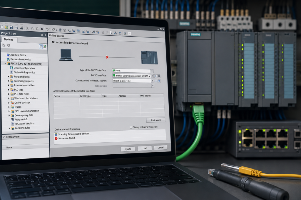
A Siemens HMI powers up normally, displays its configured screens and accepts operator input—but every PLC value is missing, frozen or replaced by communication-error symbols.
Alarms may report:
- connection interrupted;
- PLC not reachable;
- communication partner unavailable;
- tag cannot be updated;
- connection establishment failed;
- controller in protected state;
- certificate not trusted.
The PLC may still be in RUN, and another engineering computer may be able to reach it.
The most common causes are:
- wrong PLC IP address;
- incorrect HMI connection type or partner;
- HMI tags linked to deleted or changed PLC tags;
- PLC protection settings blocking HMI access;
- PLC or HMI project changed without a consistent compile and download;
- Ethernet cable, connector or switch failure.
Before changing anything, determine whether the entire HMI connection has failed or whether only certain tags are affected.
That first distinction prevents a great deal of unnecessary network troubleshooting.
Quick Troubleshooting Table
| Symptom | Most likely causes |
|---|---|
| Every PLC value is unavailable | Wrong IP, broken Ethernet connection, wrong connection partner, CPU protection or incompatible project |
| Only one screen or several tags fail | Deleted PLC tags, renamed DB elements, wrong tag connection or HMI not recompiled |
| HMI communicates until the PLC is replaced | New PLC IP, firmware, certificate, protection or project mismatch |
| HMI communicates until its project is updated | Incorrect connection selected, incomplete HMI download or invalid tag references |
| PLC can be pinged from a laptop but HMI remains offline | HMI has wrong IP/subnet, wrong PLC address, connection type or security settings |
| HMI LINK LED is off | Cable, connector, switch port or HMI Ethernet-interface problem |
| Connection works with a direct cable | Plant switch, VLAN, cable, routing or network configuration problem |
| Values display but cannot be written | PLC access rights, HMI tag write access, protected variable or unsuitable data type |
| Old values remain on screen | Connection lost after values were last updated or acquisition mode is incorrect |
| Communication fails after PLC tag changes | PLC blocks and HMI project were not compiled and downloaded consistently |
First Determine What Has Actually Failed
Not every HMI problem means that the complete PLC connection is down.
Entire Connection Is Down
Typical signs include:
- every external tag is unavailable;
- all PLC-controlled animations stop;
- process values disappear across every screen;
- connection-related system alarms appear;
- HMI cannot read or write any PLC data.
Focus on:
- Ethernet connection;
- HMI and PLC IP settings;
- configured connection partner;
- PLC protection;
- certificates;
- HMI runtime connection status.
Only Certain Tags Are Down
Typical signs include:
- most screens still work;
- only a recently modified screen fails;
- one DB or machine section is affected;
- some values display while others remain invalid;
- problem began after PLC tag or data-block changes.
Focus on:
- deleted or renamed PLC tags;
- changed data types;
- changed DB structure;
- HMI tags connected to the wrong PLC;
- incomplete compilation;
- old HMI runtime project.
External HMI tags represent data locations in the connected PLC. Their addresses and available data types therefore depend on the configured controller and connection.
Values Work but Buttons Do Not
If the HMI can read PLC values but cannot write commands, the network connection is probably operating.
Check:
- PLC access rights;
- tag write permissions;
- user authorisation on the HMI;
- PLC program immediately overwriting the HMI command;
- wrong tag data type;
- tag linked to an input or read-only structure;
- secure communication or certificate issue.
A read-only problem should not be approached as if the Ethernet cable were disconnected.
Start With the HMI System Alarms
Before restarting the HMI, open its alarm or diagnostic view and record the complete communication message.
Useful details may include:
- connection name;
- PLC name;
- IP address;
- error number;
- failed tag;
- certificate warning;
- authentication failure;
- timeout;
- controller-protection message.
For classic WinCC panels and Runtime Advanced, communication-driver alarms can distinguish connection, configuration, certificate and tag-related problems. Siemens documents, for example, alarms for rejected connections, protected CPU states and untrusted PLC certificates.
For WinCC Unified, inspect:
- system alarms;
- Runtime diagnostics;
- configured connection;
- certificate and security information;
- tag quality.
Record the first communication error rather than only the dozens of tag failures that follow it.
One failed PLC connection can generate hundreds of secondary tag alarms.
1. Wrong PLC IP Address
The HMI connection must point to the actual IP address of the PLC interface being used.
A mismatch commonly appears after:
- CPU replacement;
- PLC factory reset;
- project copied from another machine;
- IP address changed during commissioning;
- HMI project restored from an older backup;
- connection moved to another CPU interface;
- machine network renumbered.
Example
The physical PLC now uses:
192.168.10.20The HMI connection still points to:
192.168.10.10The HMI may continue attempting to connect indefinitely, but it is contacting the wrong address.
Check the PLC Address
In TIA Portal:
- Open Device configuration.
- Select the PLC’s PROFINET interface.
- Open Properties → Ethernet addresses.
- Record:
- IP address;
- subnet mask;
- interface name;
- connected subnet.
Then go online with the PLC and confirm that the online address matches the project.
Do not assume the offline project is current.
Check the Address in the HMI Connection
Open the HMI device and inspect:
Connections
Depending on the WinCC generation, check:
- connection partner;
- communication path;
- PLC address;
- selected PLC interface;
- subnet;
- rack and slot where applicable.
For an HMI connection to an S7-1200 over PROFINET, Siemens requires the relevant IP and subnet parameters to be configured as part of the connection.
Check the HMI’s Own IP Address
The HMI also needs a valid, unique IP address.
Example:
PLC
IP address: 192.168.10.20
Subnet mask: 255.255.255.0
HMI
IP address: 192.168.10.30
Subnet mask: 255.255.255.0
Both devices are in the same local subnet and have unique addresses.
A problematic example would be:
PLC: 192.168.10.20 / 255.255.255.0
HMI: 192.168.20.30 / 255.255.255.0
Without routing, those devices are in different subnets.
Verify the Runtime Address
The HMI may contain a runtime network configuration that differs from the offline project.
On the physical panel, inspect its Control Panel or network settings and confirm:
- IP address;
- subnet mask;
- gateway where required;
- active Ethernet interface.
After replacing or resetting a panel, the project can be correct while the panel’s operating-system network settings remain wrong.
Check for Duplicate IP Addresses
A duplicate address can produce intermittent communication or cause the HMI to connect to the wrong device.
Possible signs include:
- communication works when another machine is off;
- values freeze and recover randomly;
- ping response changes;
- connection works after disconnecting another device;
- the wrong MAC address appears for the PLC IP.
Use an approved network-scanning or ARP-check procedure and compare the responding MAC address with the physical PLC.
Do not assign an apparently unused IP without checking the plant network plan. The intended owner may simply be powered off.
2. Wrong Connection Type or Connection Partner
An HMI can be physically connected to the correct PLC while its WinCC connection is configured for the wrong controller, interface or protocol.
Possible mistakes include:
- S7-300/400 connection selected for an S7-1200/1500;
- wrong CPU selected as the connection partner;
- HMI connection linked to a deleted or replacement PLC;
- connection configured through the wrong CPU interface;
- non-integrated connection used where an integrated connection is required;
- PROFIBUS connection selected instead of Industrial Ethernet;
- incorrect rack or slot settings on older controllers;
- connection copied from another project without changing its partner.
WinCC supports different PLC families through specific communication channels, and the available addressing method depends on the configured HMI connection.
Integrated HMI Connection
When the HMI and PLC are in the same TIA Portal project, the preferred configuration is normally an integrated connection.
The network view connects:
- HMI Ethernet interface;
- PLC Ethernet interface;
- common subnet;
- logical HMI connection.
TIA Portal can then maintain symbolic references between HMI tags and PLC tags more reliably.
Non-Integrated Connection
A non-integrated connection may be used when:
- PLC and HMI are in separate projects;
- HMI communicates with an externally managed controller;
- project architecture requires manual connection parameters.
However, more values may need to be entered manually:
- controller type;
- PLC IP;
- rack;
- slot;
- connection driver;
- route.
Not every controller and Runtime combination supports every non-integrated connection arrangement. Siemens notes, for example, that a non-integrated WinCC connection to an S7-1500 software controller is not supported.
Check the Configured Partner
Open the HMI connection table and verify:
- correct PLC name;
- correct PLC device;
- correct Ethernet interface;
- correct connection driver;
- correct network path.
If the project contains several similar CPUs, confirm that the HMI is connected to the intended one.
A connection called HMI_Connection_1 tells you very little.
The partner column tells you where it actually points.
Check After Copying an HMI
When an HMI is copied into another project or machine module, the copied connection may still reference the original PLC.
Siemens instructs users copying HMI devices with connections to reconnect the new HMI to the required network and explicitly select the intended PLC under the connection’s Partner setting.
Check Routed Connections
If the HMI reaches the PLC through another controller or network route, verify the complete configured path.
A routed HMI connection may need to be adapted after:
- changing HMI device type;
- changing PLC configuration;
- replacing routing equipment;
- moving the PLC to another interface.
Siemens specifically notes that routed HMI connections must be adapted when the HMI type or PLC configuration changes.
Wrong Rack or Slot
Rack and slot settings are especially relevant to:
- S7-300;
- S7-400;
- certain non-integrated or routed connections;
- older communication drivers.
A common S7-300 connection may expect:
Rack: 0
Slot: 2
However, the correct values depend on the real hardware and connection type.
Do not copy rack and slot values from an unrelated project.
For integrated S7-1200 and S7-1500 connections, TIA Portal normally manages the partner relationship through the configured device rather than requiring the same manual approach used for older controllers.
3. HMI Tags Point to Deleted or Changed PLC Tags
A healthy HMI connection does not guarantee that every tag reference is valid.
The connection may be fully operational while individual HMI objects point to:
- a deleted PLC tag;
- a renamed DB;
- a renamed structure member;
- a changed data type;
- a tag moved into another PLC;
- an address that no longer exists;
- an outdated absolute address.
How HMI Tags Access PLC Data
An external HMI tag is linked to a PLC memory location.
With Siemens controllers, the reference may be:
- symbolic;
- absolute.
Symbolic Addressing
The HMI tag references the PLC item by its symbolic identity.
Example:
"Motor_DB".RunningSymbolic addressing is generally preferred for S7-1200 and S7-1500 systems. Siemens states that symbolic addressing performs validity checks and can automatically track some address-location changes.
Absolute Addressing
The HMI tag refers to a specific memory address.
Example:
DB10.DBX4.0If the PLC structure changes and the data moves, the HMI may continue reading the old address unless it is updated, compiled and downloaded.
For S7-300/400 HMI communication, absolute addressing is commonly required, and changes to PLC addresses must be followed by recompilation and loading of the HMI project.
What Happens When a PLC Tag Is Deleted?
An HMI tag may remain in the visualization project even after its connected PLC tag is deleted or renamed.
Possible symptoms include:
- one value shows an invalid quality;
- object displays dashes or a communication marker;
- compile warning identifies an unresolved reference;
- input field cannot write;
- alarm trigger stops working;
- screen script reports an invalid tag;
- Runtime logs a tag error.
Changes That Require HMI Recompilation
For symbolic addressing, Siemens identifies changes that require recompiling and reloading the WinCC project, including changes to:
- linked PLC tag or DB-element name;
- linked data type;
- higher-level structure name or type;
- connected data-block name.
Changing only the physical memory address may be handled differently with a valid symbolic reference, but name and type changes directly affect the HMI link.
Step-by-Step Tag Check
Step 1: Identify an affected object
Select a screen field, animation, alarm or script that no longer works.
Step 2: Open its HMI tag
Check:
- tag name;
- configured connection;
- PLC tag;
- symbolic address;
- data type.
Step 3: Open the referenced PLC item
Confirm that the referenced:
- DB exists;
- tag exists;
- structure path exists;
- data type matches;
- PLC connection is correct.
Step 4: Use Cross-Reference
Search where the HMI tag and PLC tag are used.
This can reveal:
- several HMI tags still pointing to an old DB;
- one screen connected to another PLC;
- alarm triggers using a deleted tag;
- scripts using a renamed HMI tag.
Step 5: Reconnect invalid tags
Select the current PLC tag from the PLC tag table or data block rather than manually typing an assumed symbolic path.
Step 6: Compile PLC and HMI
Compile modified PLC blocks first, followed by the HMI project. Siemens recommends compiling changed S7 blocks before compiling an HMI that uses connected PLC tags.
Step 7: Download Both Projects
If only the PLC was downloaded, the physical HMI may still be running old tag references.
If only the HMI was downloaded, the physical PLC may still contain the old block structure.
Changed Data Type
Suppose the PLC tag was originally:
INTand was changed to:
REALThe HMI object may still be configured for the old data type.
Possible results include:
- compile errors;
- incorrect display;
- failed write operation;
- invalid quality;
- scaling problems.
Reconnect or synchronise the tag and review:
- display format;
- limits;
- alarm thresholds;
- scripts;
- recipes;
- archived values.
HMI Tag Connected to the Wrong PLC
Projects with several CPUs can contain HMI tags that look correct but use the wrong connection.
Check the Connection column in the HMI tag table.
WinCC allows an external HMI tag’s PLC connection to be changed, so imported or copied tags can end up associated with another controller.
4. PLC Protection Settings Block HMI Access
Modern Siemens CPUs can restrict who or what may read and write PLC data.
The CPU may be reachable over Ethernet but reject the HMI connection because of:
- insufficient access level;
- missing password;
- secure communication required;
- incorrect or untrusted certificate;
- HMI access to specific data not permitted;
- legacy communication disabled;
- project security settings changed.
Access Levels
S7-1200 and S7-1500 protection settings can assign permissions for:
- full access;
- read access;
- HMI access;
- no access;
- fail-safe access where applicable.
Siemens documents that users with suitable CPU access privileges can read and write PLC variables and that access-control settings are configured under the CPU’s protection and security properties.
The exact options depend on:
- CPU family;
- firmware;
- TIA Portal version;
- project security configuration.
Secure PG/PC and HMI Communication
Newer S7-1200 and S7-1500 systems can require secure communication between the PLC and HMI.
The connection may depend on:
- PLC communication certificate;
- HMI trust store;
- project-generated certificate;
- CPU firmware;
- HMI image or Runtime version.
Siemens states that, after applicable firmware transitions, certificates can become mandatory for secure PG/PC and HMI communication and that the connection establishment depends on the configured certificate type.
Typical Security Symptoms
- PLC responds to ping.
- TIA Portal can go online.
- HMI reports authentication failure.
- Runtime reports that the PLC certificate is untrusted.
- Old HMI project worked before CPU replacement.
- Communication stopped after enabling secure-only communication.
- Reading works, but writing is rejected.
- New PLC firmware no longer accepts the older connection mechanism.
Check the PLC Settings
In TIA Portal, inspect:
PLC Properties → Protection & Security
Review:
- access control;
- access passwords;
- connection mechanisms;
- secure PG/PC and HMI communication;
- PLC certificate;
- permitted communication partners.
Siemens exposes the secure-only setting under the CPU’s protection and security connection mechanisms.
Check the HMI Certificate
For secure communication, make sure the HMI runtime trusts the PLC certificate expected by the project.
Problems may appear after:
- CPU replacement;
- project restored from backup;
- certificate regenerated;
- PLC firmware upgrade;
- HMI operating-system update;
- HMI project compiled in another project context.
Do not simply disable security to make the connection work.
Correct the project, certificates and compatible device versions.
PLC Tag Access Attributes
Some PLC data can have attributes controlling whether it is accessible from HMI or other external services.
When creating or modifying data structures, confirm that required variables are configured for HMI access where the CPU and programming model use such attributes. Siemens’ documentation describes HMI visibility and accessibility properties for PLC data used by visualization systems.
If one DB fails while other PLC tags work, inspect the affected data’s access attributes before blaming the Ethernet network.
5. PLC or HMI Project Was Changed
Communication often fails after an otherwise successful software modification.
Typical changes include:
- PLC IP address changed;
- PLC device replaced;
- HMI connection renamed;
- HMI connected to another CPU;
- DB renamed;
- PLC tag deleted;
- structure or UDT changed;
- CPU security enabled;
- certificate regenerated;
- HMI device replaced;
- project upgraded to another TIA Portal version.
The engineering project may look correct, but the physical devices can contain different versions.
Common Inconsistent States
New PLC, old HMI
The PLC contains new tags, security settings or IP configuration, while the HMI still runs the previous project.
Old PLC, new HMI
The HMI expects new DBs or tags that were never downloaded to the PLC.
Offline project differs from both devices
A technician opened an old backup, changed one screen and downloaded it to the HMI.
The HMI now contains old connection and tag information.
Partial compile
Only changed objects were compiled, leaving inconsistent references.
Partial download
The PLC project was downloaded, but the HMI download was forgotten—or vice versa.
Compile in the Correct Order
A reliable sequence is:
- Compile modified PLC software.
- Correct all PLC errors.
- Compile or rebuild the HMI software.
- Correct all HMI errors and important warnings.
- Download the PLC where required.
- Download the HMI.
- Restart Runtime if required.
- Verify the physical connection.
Siemens advises compiling changed S7 blocks before compiling an HMI that uses those PLC tags. When internal WinCC compile errors or warnings occur, Siemens recommends a complete HMI rebuild using Compile → Software (rebuild all).
Changes-Only Compile vs Rebuild All
A changes-only compile is faster but may not uncover every inconsistency.
Use Rebuild all when:
- communication failed after substantial changes;
- PLC tags or UDTs were modified;
- HMI was copied or migrated;
- connection partner was replaced;
- unexplained internal compile warnings exist;
- project was upgraded;
- online HMI behavior differs from the offline project.
Siemens notes that some address parameters are not checked during a changes-only hardware-and-software compile, which is another reason a full rebuild can be valuable during diagnosis.
Check Online and Offline Versions
Confirm:
- physical PLC IP matches the project;
- HMI runtime project has the expected date or version;
- PLC blocks are current;
- HMI connection partner is current;
- HMI tag references are current;
- certificates match.
A successful compile proves that the offline project is internally acceptable.
It does not prove that both physical devices contain that project.
HMI Device Replacement
After changing the configured HMI type, communication settings may need to be adapted.
Siemens provides specific procedures for adapting a connection after HMI replacement and warns that connection configuration may need adjustment.
Check:
- panel type;
- device version;
- supported communication driver;
- Ethernet interface;
- secure communication support;
- runtime image.
6. Ethernet Connection Failure
If every external tag is unavailable, inspect the physical network.
Check Device Power
Verify:
- PLC power;
- HMI power;
- Ethernet switch power;
- remote cabinet supply;
- 0V return.
An HMI screen can remain on while a separate network switch has lost power.
Check LINK LEDs
Inspect the Ethernet ports on:
- PLC;
- HMI;
- switch;
- intermediate network equipment.
LINK Off
Suspect:
- disconnected cable;
- damaged connector;
- unpowered switch;
- failed port;
- wrong HMI port;
- disabled interface.
LINK On
The physical Ethernet link is established.
Continue checking:
- IP and subnet;
- duplicate IP;
- VLAN;
- connection partner;
- protection settings.
A green LINK light does not prove that WinCC communication is established.
Inspect the Cable
Check for:
- loose RJ45 plug;
- damaged M12 connector;
- crushed cable;
- broken conductor near strain relief;
- cabinet-door damage;
- moisture;
- poorly assembled field connector;
- excessive bending;
- cable pulled from a switch.
If communication fails only when the machine moves, inspect flexible cable runs and drag chains.
Test With a Known-Good Cable
Where safe:
- Connect the HMI and PLC through a short known-good cable or approved test switch.
- preserve the original IP settings.
- verify LINK.
- restart or reconnect Runtime where required.
- observe communication.
If the connection returns, inspect the original cable and switch path.
Check the Switch
A managed switch may maintain LINK while blocking communication because of:
- wrong VLAN;
- port security;
- access-control rule;
- disabled port;
- network loop protection;
- duplicate address;
- configuration error.
If several devices disappear together, check common infrastructure such as:
- main switch;
- uplink cable;
- remote cabinet switch;
- common 24V supply.
Direct Ping Test
Some HMI devices provide a ping or network-test function in their Control Panel.
Test:
- HMI to PLC;
- engineering PC to PLC;
- engineering PC to HMI.
Interpret the results carefully:
- Neither PLC nor HMI can be pinged: common cable or switch problem.
- Both can be pinged from the PC: physical IP communication works; check HMI connection and security.
- HMI cannot ping PLC but PC can: HMI subnet, gateway, VLAN or physical route is wrong.
- HMI can ping PLC but Runtime is offline: check the WinCC connection type, partner, security and project consistency.
Ping proves IP reachability.
It does not prove that the configured HMI communication driver can access the PLC.
HMI Can Ping the PLC but Still Does Not Communicate
This symptom narrows the problem.
It suggests that:
- the Ethernet path works;
- IP addresses are routable;
- the PLC responds to network traffic.
Focus next on:
- connection partner;
- communication driver;
- PLC model;
- rack and slot where applicable;
- protection and certificate settings;
- incompatible HMI or PLC firmware;
- old Runtime project.
Check the Runtime Connection
The HMI’s configured connection may point to:
- another IP;
- another PLC;
- another Ethernet interface;
- an invalid route.
Do not assume the address shown in the HMI operating system is the same address stored in the WinCC connection.
The HMI has its own IP address, while the connection configuration contains the PLC partner’s address.
Check PLC Compatibility
Confirm:
- CPU family;
- full order number;
- firmware;
- configured hardware version;
- HMI device version;
- WinCC generation.
A connection driver configured for another CPU family may fail even though the target responds to ping.
Communication Works, but Some Values Show Dashes
When only certain values fail, do not restart switches or replace cables.
Check the affected HMI tags.
Possible Causes
- deleted PLC tag;
- renamed DB;
- changed PLC data type;
- symbolic path no longer valid;
- HMI tag points to the wrong connection;
- absolute address changed;
- tag is not accessible from HMI;
- HMI was not recompiled and downloaded.
Compare One Working and One Failed Tag
Open both HMI tags and compare:
- connection;
- PLC tag path;
- data type;
- acquisition mode;
- address;
- access attributes.
A comparison often reveals the difference immediately.
Rebuild the References
If many tags are invalid after a PLC structure change:
- compile the PLC.
- update or synchronise HMI tags.
- reconnect unresolved references.
- rebuild the HMI software.
- download the HMI.
- confirm tag quality in Runtime.
HMI Reads Values but Cannot Write to the PLC
This is usually not a complete communication failure.
Check PLC Protection
Confirm that the active HMI connection has sufficient write access.
Check HMI User Permissions
A button or input field may require an HMI user role.
This is separate from PLC communication protection.
Check the PLC Program
The HMI may successfully write a value that the PLC program immediately resets.
Use online monitoring to see whether the variable changes briefly.
Check the Tag Data Type
Writing can fail when:
- HMI and PLC types differ;
- value exceeds the permitted range;
- structure is incompatible;
- object uses a read-only tag;
- the driver does not support the requested operation.
Check the Addressed Memory
Avoid writing directly to process inputs.
PLC input memory is updated from field hardware and is not a suitable persistent command location.
Use a defined command tag or DB variable designed for HMI control.
Communication Failed After Replacing the PLC
A replacement CPU may introduce several differences at once:
- different IP address;
- different firmware;
- new certificate;
- new access settings;
- incomplete program download;
- wrong CPU model;
- changed communication interface.
Recovery Checklist
- Compare the complete CPU order number.
- check firmware compatibility.
- verify PLC IP and subnet.
- verify the HMI connection partner.
- download the correct PLC project.
- check protection settings.
- regenerate or load certificates where required.
- rebuild and download the HMI.
- confirm physical Ethernet communication.
Do not reduce security or enable legacy communication without understanding why the replacement differs.
Communication Failed After Replacing the HMI
A replacement panel may have:
- factory IP settings;
- no project;
- old operating-system image;
- incompatible device version;
- missing certificate;
- incorrect transfer settings.
Check:
- exact HMI model and device version;
- runtime or panel image;
- panel IP and subnet;
- downloaded HMI project;
- PLC connection;
- certificates;
- user administration;
- Ethernet interface.
A panel that displays the correct screens may still be running an old backup with outdated PLC connection information.
Complete Step-by-Step Troubleshooting Procedure
Step 1: Make the Machine Safe
Restoring HMI communication can allow queued commands, operator actions or automatic sequences to become active.
Control hazardous equipment before downloading or reconnecting devices.
Step 2: Determine the Scope
Ask:
- Are all external tags down?
- Are only some tags down?
- Can the HMI read but not write?
- Did the fault begin after a project or hardware change?
Step 3: Record HMI Alarms
Write down the full error code and text.
Step 4: Check CPU State
Confirm the PLC is:
- powered;
- in RUN where expected;
- free from relevant ERROR or SF diagnostics.
Step 5: Check LINK LEDs
Inspect the HMI, PLC and switch.
Step 6: Verify HMI and PLC IP Settings
Confirm:
- unique addresses;
- compatible subnet masks;
- correct PLC address in the HMI connection.
Step 7: Test Basic Network Reachability
Use the HMI’s approved network-test function or an engineering computer.
Step 8: Inspect the HMI Connection
Verify:
- driver;
- PLC partner;
- interface;
- route;
- rack and slot where applicable.
Step 9: Check Protection and Certificates
Review PLC security and HMI trust settings.
Step 10: Inspect Failed HMI Tags
If only some values fail, verify the symbolic or absolute PLC references.
Step 11: Compile the PLC
Compile every changed block and data type.
Step 12: Rebuild the HMI
Use a complete software rebuild when inconsistency is suspected.
Step 13: Download Both Devices
Make sure the PLC and HMI contain matching project versions.
Step 14: Restart Runtime
Restart only as required by the panel or Runtime procedure.
Step 15: Confirm Communication
Check:
- connection alarm clears;
- external tags update;
- commands write successfully;
- alarms and recipes work;
- data quality is valid.
Step 16: Test the Complete Machine Cycle
A single displayed value does not prove that every HMI function is healthy.
Test:
- commands;
- status indications;
- alarms;
- recipes;
- trends;
- setpoints;
- user access;
- safety-related displays.
Symptom-Based Troubleshooting
Every PLC Value Is Missing
Check:
- HMI connection alarm.
- PLC IP in the connection.
- HMI IP and subnet.
- LINK LEDs.
- PLC connection partner.
- CPU protection.
- certificate.
- HMI project version.
One Screen Does Not Work
Check:
- tags used on that screen.
- tag connection column.
- renamed or deleted DB.
- changed data type.
- scripts and animations.
- HMI compile warnings.
HMI Worked Until the PLC Project Changed
Check:
- deleted tags.
- DB or UDT changes.
- changed PLC IP.
- changed protection settings.
- PLC compile.
- HMI rebuild.
- download of both projects.
HMI Worked Until the PLC Was Replaced
Check:
- physical CPU IP.
- firmware.
- project download.
- CPU certificate.
- access level.
- correct interface.
HMI Worked Until the Panel Was Replaced
Check:
- panel IP.
- device type and version.
- correct project download.
- runtime image.
- certificate.
- connection partner.
HMI Can Ping the PLC but Remains Offline
Check:
- configured PLC IP inside the HMI connection.
- connection type.
- PLC partner.
- rack and slot where relevant.
- CPU protection.
- certificate compatibility.
- HMI runtime version.
Some Tags Read, but Others Do Not
Check:
- deleted PLC tags.
- symbolic path.
- data type.
- access attributes.
- correct PLC connection.
- HMI compilation.
Values Read, but Buttons Do Not Work
Check:
- PLC write permissions.
- HMI user authorisation.
- tag write access.
- PLC program overwriting commands.
- data-type compatibility.
Connection Fails Randomly
Check:
- duplicate IP.
- loose cable.
- unstable switch power.
- damaged connector.
- CPU or HMI power dips.
- certificate or session diagnostics.
- network congestion or managed-switch configuration.
What Not to Do
Avoid these common mistakes:
- Do not factory-reset the PLC first.
- Do not reset the HMI before recording its communication alarms.
- Do not change random IP addresses.
- Do not give the HMI and PLC the same IP.
- Do not replace the Ethernet cable when only one tag is invalid.
- Do not assume ping proves the WinCC connection is correctly configured.
- Do not disable PLC security permanently.
- Do not enable legacy communication without a security review.
- Do not download an old HMI backup blindly.
- Do not compile only the HMI after changing PLC tags.
- Do not ignore compile warnings about invalid references.
- Do not assume a green LINK LED means that the HMI connection is established.
- Do not replace the panel before checking its project and IP settings.
- Do not restore operator control until the machine is in a safe condition.
The goal is not merely to remove the communication alarm.
The goal is to make sure the HMI is exchanging the correct data with the correct PLC.
Why the HMI Cannot Communicate With the Siemens PLC
A Siemens HMI normally loses communication for one of three broad reasons.
Network Path Failure
- wrong IP address;
- wrong subnet;
- duplicate IP;
- damaged cable;
- failed switch;
- incorrect VLAN or route.
Connection or Security Failure
- wrong PLC partner;
- wrong communication driver;
- wrong CPU interface;
- access protection;
- certificate mismatch;
- unsupported device combination.
Project or Tag Failure
- deleted PLC tag;
- renamed DB;
- changed data type;
- old HMI project;
- incomplete compile;
- PLC and HMI downloads do not match.
Use this order:
Scope of fault → HMI alarm → Ethernet LINK → IP settings → connection partner → security → tag references → compile and download
When every value is missing, begin with the network and connection.
When only a few values are missing, begin with the tags.
The HMI screen can look perfectly healthy while its connection is completely wrong—and one broken tag can look like a network failure if you start troubleshooting at the wrong layer.