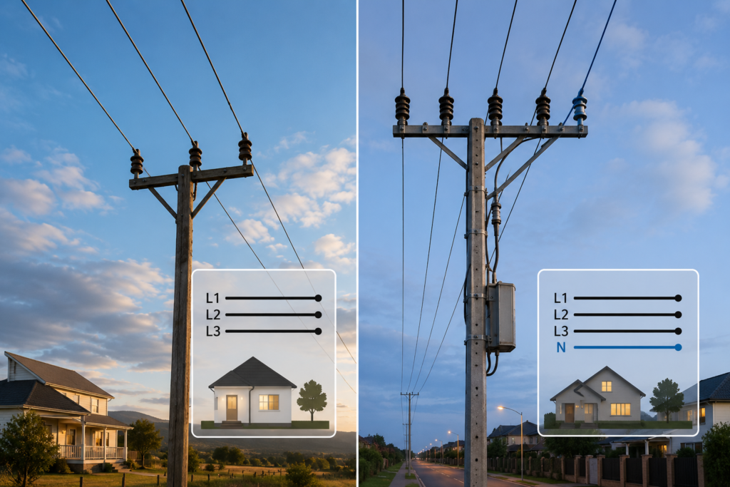
Look up at one utility pole and you might see three large wires stretched neatly across the top.
A few streets later, there are four.
Then comes another pole with six conductors, a thin wire above everything else and several lower cables that may not even belong to the electricity network.
It looks inconsistent. It usually isn’t.
The number of wires depends on what the line is carrying, whether a neutral conductor is required, the voltage level, the grounding arrangement and whether the line includes protection against lightning.
So, why do power lines have three wires?
Most commonly, those three wires are the three phase conductors of a three-phase AC system. A fourth wire may be a neutral conductor, but not always. On high-voltage transmission towers, the extra wire at the very top is often a shield or earth wire instead.
Same number of wires. Completely different job.
Why Three-Phase Power Uses Three Wires
Large electrical systems commonly use three-phase alternating current.
Instead of producing one alternating voltage, a three-phase generator produces three voltages that reach their peaks at different times. Each phase is shifted by 120 electrical degrees from the others.
The three phase conductors are often identified as:
- L1
- L2
- L3
Or sometimes:
- Phase A
- Phase B
- Phase C
Each conductor carries an alternating current. Together, the three phases provide a smooth and efficient way to transmit electrical power.
Three-phase systems are widely used because they offer several advantages:
- More constant power delivery
- Efficient operation of large motors
- Less conductor material for a given transmitted power
- Better suitability for high-power equipment
- Easier distribution of large electrical loads
- Naturally rotating magnetic fields in motors
A large factory motor, for example, can run directly from the three phase conductors without requiring a neutral.
That is one reason many industrial and medium-voltage lines have only three main wires.
Why Three Phases Do Not Always Need a Neutral
In a balanced three-phase system, the currents in the three phase conductors cancel one another at the common point.
Imagine three identical loads:
L1 → Load 1
L2 → Load 2
L3 → Load 3
Each load draws the same current, and the three currents are displaced by 120 degrees.
At any instant, the mathematical sum of the three currents is zero.
That means no separate neutral conductor is needed to carry return current.
This is very different from a basic single-phase circuit, where current leaves through the line conductor and returns through neutral.
In a balanced three-phase circuit, each phase effectively forms part of the return path for the others.
No conductor permanently acts as “the return wire.” The current relationships change continuously as the AC waveforms rise, fall and reverse.
This is why three-wire systems are common for:
- Three-phase motors
- Large industrial heaters
- High-voltage transmission
- Medium-voltage distribution
- Pumps
- Compressors
- Large ventilation systems
- Transformers supplied from three phases
If the load only needs phase-to-phase voltage, neutral has little to do.
When a Fourth Neutral Wire Is Added
A neutral conductor becomes useful when the system needs to supply loads connected between one phase and neutral.
These are often ordinary single-phase loads such as:
- Lighting
- Wall outlets
- Small appliances
- Office equipment
- Domestic electronics
- Control circuits
- Small pumps
- Heating controls
A three-phase, four-wire system contains:
L1
L2
L3
Neutral
This arrangement allows the network to supply both:
- Three-phase loads connected between phases
- Single-phase loads connected between one phase and neutral
For example, a European low-voltage network may provide approximately:
- 400 V between two phases
- 230 V between one phase and neutral
A three-phase motor can use L1, L2 and L3.
A household lamp can use L1 and neutral.
Both are supplied from the same distribution system.
That is extremely practical, especially in residential streets, commercial buildings and mixed-use areas.
What Does the Neutral Conductor Do?
The neutral conductor carries the imbalance current created by single-phase loads.
Suppose a group of homes is connected across a three-phase distribution system:
- Several homes are connected to L1.
- Others are connected to L2.
- The rest are connected to L3.
Utility designers try to distribute the loads evenly, but real consumption is never perfectly balanced.
One household may be cooking dinner. Another may be almost empty. A workshop on the third phase may have just started a compressor.
Because the phase currents are unequal, they no longer cancel perfectly.
The neutral carries the remaining difference.
In simplified form:
Neutral current = imbalance between phase currentsIf all three phase currents were identical and perfectly sinusoidal, the neutral current could theoretically be close to zero.
In reality, neutral current is often present because loads constantly switch on and off.
Modern electronic equipment can complicate things further. Computers, LED lighting, chargers and switching power supplies may create harmonic currents. Some harmonic components can add together in the neutral rather than cancelling.
So the neutral should never be treated as an unused spare wire.
It can carry substantial current.
Three-Wire and Four-Wire Distribution Systems
The difference is especially visible on distribution poles.
Three-wire distribution
A three-wire distribution line normally carries three phase conductors without a neutral.
This is common when:
- Loads are mainly three-phase
- Transformers are connected phase-to-phase
- The neutral is not distributed along that section
- The system uses a delta arrangement
- It is a medium-voltage feeder
- Single-phase loads are supplied through transformers connected between phases
You may see three conductors arranged horizontally:
L1 L2 L3Or vertically:
L1
L2
L3The physical arrangement depends on pole design, voltage, clearance requirements and local utility practice.
Four-wire distribution
A four-wire distribution line usually contains three phases and a neutral:
L1
L2
L3
N
This is commonly associated with a grounded star, or wye, system.
The neutral is connected to the star point of the supply transformer and may be grounded at multiple locations according to the network design and local rules.
A four-wire system is useful where utilities need to supply many single-phase customers from a three-phase feeder.
Is the Fourth Wire Always Neutral?
No.
This is where simply counting conductors can mislead you.
A fourth wire could be:
- A neutral conductor
- A shield wire
- An earth wire
- A static wire
- A communication conductor
- A messenger wire
- Part of a second circuit
- A separate street-lighting conductor
Its position provides a clue, but not absolute proof.
A conductor running below the three phases on a distribution pole may be neutral.
A wire running above all the phase conductors on a transmission tower is more likely to be a shield or earth wire.
And a lower cable may belong to telecommunications rather than the power circuit at all.
Electrical poles are sometimes shared real estate. Everyone wants a spot, nobody wants to pay for a second pole.
What Is a Shield or Earth Wire?
High-voltage transmission lines often have one or two smaller conductors positioned above the main phase conductors.
These may be called:
- Shield wires
- Earth wires
- Ground wires
- Static wires
- Overhead ground wires
Their primary job is to protect the phase conductors from direct lightning strikes.
Because the shield wire is mounted above the energized phases, lightning is more likely to strike it first.
The lightning current then travels through:
- The shield wire
- The tower structure
- Grounding conductors
- Tower foundations
- Grounding electrodes
- The surrounding earth
The shield wire does not normally carry the main load current.
It is a protective conductor, not another phase.
A transmission tower may therefore appear to have four wires:
Shield wire
L1
L2
L3
That does not make it a three-phase, four-wire supply in the same sense as a low-voltage system with a neutral.
The number is the same. The circuit arrangement is not.
Some Shield Wires Also Carry Communication Signals
Modern overhead ground wires may contain optical fibres.
These are commonly known as optical ground wires, or OPGW.
An OPGW cable performs two jobs:
- It helps protect the transmission line from lightning.
- It carries fibre-optic communication signals.
Utilities can use those fibres for:
- Protection relays
- Substation communication
- Network control
- SCADA systems
- Voice and data
- Fault-location systems
- Remote monitoring
From the ground, it may look like an ordinary thin wire above the phases.
Inside, it is part lightning shield and part high-speed data cable. Rather a talented piece of metalwork.
Transmission Lines Usually Use Three-Phase Power
Long-distance power transmission is almost always three-phase AC where alternating-current transmission is used.
A basic single-circuit transmission line therefore requires three phase conductors.
However, large towers often carry more than three visible wires because they may include:
- One three-phase circuit
- Two three-phase circuits
- One or two shield wires
- Bundled conductors for each phase
- Communication cables
A double-circuit tower may carry six phase positions:
Circuit 1: L1, L2, L3
Circuit 2: L1, L2, L3
Add two shield wires above them and the tower now appears to carry eight conductors.
But electrically, it may still be just two ordinary three-phase circuits.
Why One Phase May Use Several Wires
On high-voltage transmission lines, one phase is not always represented by one physical conductor.
Instead, each phase may use a bundle of two, three, four or more conductors separated by spacers.
For example:
Phase L1: four bundled conductors
Phase L2: four bundled conductors
Phase L3: four bundled conductors
The tower now carries twelve large wires, but electrically they form only three phases.
Bundled conductors can:
- Increase current-carrying capability
- Reduce corona discharge
- Reduce audible noise
- Lower electric-field intensity at the conductor surface
- Improve transmission performance
- Reduce certain electrical losses
So counting every visible wire does not necessarily tell you the number of phases.
Several wires may be working together as one phase.
Distribution Lines and Transmission Lines Are Not the Same
People often call every overhead conductor a power line, but transmission and distribution systems perform different jobs.
Transmission lines
Transmission lines move large amounts of power over long distances.
They typically operate at high or extra-high voltage and connect:
- Power stations
- Major substations
- Regional networks
- Large industrial users
- Interconnection points
Transmission structures are usually:
- Taller
- Wider
- More heavily insulated
- Built with greater phase spacing
- Supported by steel towers or large poles
- Equipped with shield wires
Transmission lines commonly carry three phase conductors per circuit, often without a neutral.
At high transmission voltages, loads are generally balanced three-phase loads connected through transformers. A distributed neutral is usually unnecessary.
Distribution lines
Distribution lines deliver electricity from substations toward homes, shops and smaller industries.
They operate at lower voltage than transmission lines, although still potentially at thousands of volts.
Distribution networks may include:
- Three phase conductors
- A neutral conductor
- Pole-mounted transformers
- Fuses
- Disconnectors
- Surge arresters
- Voltage regulators
- Capacitor banks
Closer to customers, transformers reduce the voltage to the low-voltage level used by buildings and equipment.
Distribution systems vary greatly. One road may have a full three-phase feeder, while a small rural branch may use fewer conductors depending on local network design.
Why Transmission Lines Usually Do Not Have a Neutral
A transmission line transfers power between three-phase substations and transformer banks.
The loads are generally balanced enough that a neutral conductor would carry little useful current.
Adding a full-size neutral would also increase:
- Tower weight
- Construction cost
- Wind loading
- Ice loading
- Required hardware
- Maintenance requirements
If the neutral is not needed for normal operation, carrying one across hundreds of kilometres would be expensive and rather pointless.
The transformer windings at each end provide the necessary phase relationships and grounding reference.
The system may have grounded star points at substations, but that does not mean a neutral conductor must run along the entire transmission route.
Why Low-Voltage Lines Often Have Four Wires
After a distribution transformer reduces the voltage, the network must often supply many small single-phase customers.
That changes the requirements.
A low-voltage overhead line may carry:
- Three phase conductors
- One neutral conductor
Homes can then be spread across the phases to balance demand.
One property may receive L1 and neutral. Its neighbour may receive L2 and neutral. Another may receive L3 and neutral.
Larger buildings may receive all three phases plus neutral.
This allows one network to supply both modest household loads and larger three-phase equipment.
In some areas, the low-voltage conductors are separate bare or insulated wires. Elsewhere, they are bundled together as an aerial bundled cable.
The electrical principle remains similar even when the individual conductors are harder to see.
What About Single-Phase Power Lines?
Not every overhead line is three-phase.
Small rural branches may use single-phase arrangements where demand is low and a full three-phase extension would be unnecessarily expensive.
Depending on the system, a single-phase line might use:
- One phase and one neutral
- Two phase conductors
- One high-voltage conductor with earth return in specialized systems
A transformer at the end supplies a farm, house, telecommunications site or other small load.
That is why some poles carry only one or two obvious power conductors.
The network was designed for the expected load, not for visual symmetry.
Why Are Wires Mounted at Different Heights?
The arrangement is not random decoration.
Wires are placed at different heights to maintain electrical clearances, protect the system and separate services.
A typical shared pole may be arranged approximately like this:
Shield or earth wire
High-voltage phase conductors
Neutral conductor
Low-voltage conductors
Street-lighting cable
Telecommunication cables
The exact order varies by country and system, but higher-voltage conductors are generally kept above lower-voltage and communication cables.
There are several reasons.
1. Lightning Protection
A shield wire is placed at the highest point so it can intercept lightning before the strike reaches the energized phase conductors.
Its position creates a protective zone beneath it.
If the shield wire were mounted below the phases, it would not be much of a shield. It would be more of an optimistic accessory.
2. Electrical Clearance
Higher voltages require larger clearances.
The conductors must remain sufficiently separated from:
- Other phases
- Poles and towers
- Buildings
- Trees
- Vehicles
- People
- Lower-voltage circuits
- Communication equipment
Air normally acts as insulation, but it can break down when the electric field becomes strong enough.
Higher voltage means a greater risk of arcing across inadequate gaps.
That is why transmission conductors are spaced much farther apart than ordinary low-voltage wires.
3. Worker Safety
Placing telecommunications cables below electrical conductors helps separate technicians working on phone, internet or cable-TV systems from the higher-voltage equipment above.
This does not make the lower area completely safe, but it creates a more organized and controlled working environment.
Utility poles often include a defined communication zone beneath the electrical supply space.
4. Fault Protection
If a conductor breaks or sags, the vertical arrangement influences what it may contact.
Utilities try to reduce the likelihood that a high-voltage conductor will fall directly onto lower-voltage or communication circuits.
Protective devices and grounding arrangements are also designed with these possible contact faults in mind.
5. Mechanical Design
Conductors move.
Wind, ice, heat and changing load conditions can cause them to:
- Sway
- Gallop
- Sag
- Expand
- Contract
- Vibrate
The pole geometry must maintain safe spacing even when the wires are not perfectly still.
A neat-looking gap on a calm summer day may become much smaller during heavy wind or ice loading.
Why Is the Neutral Often Below the Phases?
On many distribution lines, the neutral conductor is installed below the phase conductors.
Possible reasons include:
- Easier separation from energized phases
- Simpler transformer and service connections
- Grounding and bonding practices
- Established utility construction standards
- Coordination with pole-mounted equipment
The neutral may also be connected to transformer tanks, surge arresters and grounding conductors.
But position alone cannot prove conductor identity.
Some networks place conductors in different arrangements, and insulated systems may look completely different from traditional open-wire lines.
Never identify a conductor for work purposes by looking at it from the ground.
Why Are Phase Conductors Sometimes Horizontal?
A horizontal arrangement places the three phases side by side:
L1
L2
L3
This is common on crossarm construction.
Advantages can include:
- Simple support structure
- Clear visual separation
- Convenient installation
- Predictable mechanical loading
- Easy access for certain maintenance tasks
However, the crossarm must be wide enough to maintain the required phase spacing.
Why Are They Sometimes Vertical?
A vertical arrangement places one phase above another:
L1
L2
L3This can reduce the required pole width, which is useful in:
- Narrow roads
- Urban areas
- Forest corridors
- Locations with limited right-of-way
Vertical construction may require taller poles and careful clearance planning.
Neither arrangement is automatically better. It is a design choice based on voltage, terrain, cost, loading and local standards.
Why Are Wires Sometimes Arranged in a Triangle?
Three phase conductors may also be arranged in a triangular formation:
    L2
L1      L3
This compact arrangement can provide relatively balanced spacing between phases.
Triangular configurations are found on certain distribution and transmission structures where mechanical and electrical design favour a compact shape.
The geometry also affects line inductance, capacitance and electric-field distribution.
At ordinary distribution levels, the visual arrangement may seem like a construction detail. At transmission level, conductor geometry becomes an important part of electrical performance.
Why Do Phases Sometimes Change Position?
On long transmission lines, phase conductors may periodically swap physical positions.
This is called transposition.
For part of the route, the arrangement may be:
L1 – L2 – L3Later it becomes:
L2 – L3 – L1And then:
L3 – L1 – L2The purpose is to balance the electrical characteristics of the three phases.
Because each conductor occupies a different position relative to the ground and other conductors, its inductance and capacitance can differ slightly.
By rotating the positions along the route, each phase experiences approximately the same average conditions.
You probably will not notice this from a passing car. Transmission designers certainly do.
Are All Four-Wire Lines Three Phases Plus Neutral?
No.
Four visible conductors could represent several configurations.
Three phases plus neutral
Common on distribution and low-voltage networks.
Three phases plus shield wire
Common on certain high-voltage lines.
Two independent single-phase circuits
Possible on specialized distribution arrangements.
One circuit plus a separate lighting conductor
Seen in some street networks.
Bundled phases
Several visible conductors may actually form fewer electrical phases.
Communication or control cable
One line may not carry power at all.
Without examining the equipment, insulators, connections and system drawings, you cannot identify the circuit reliably just by counting.
Can a Neutral Be Omitted From a Building Supply?
Yes, when the supplied equipment only requires three-phase, phase-to-phase voltage.
A large motor installation might receive:
L1
L2
L3
Protective earth
There is no neutral because no load is intended to operate between phase and neutral.
The protective-earth conductor is not a replacement neutral. It should not carry normal operating current.
If the installation later needs 230 V single-phase controls, designers may use:
- A control transformer
- A separate neutral supply
- A dedicated power supply
- Phase-to-phase equipment rated for the available voltage
Using protective earth as a normal return conductor is dangerous and incorrect.
Why the Protective Conductor Is Not Counted the Same Way
When people describe a power line as three-wire or four-wire, they are usually counting current-carrying circuit conductors.
A protective-earth conductor may be discussed separately.
For example, a cable described as:
3 phases + neutral + protective earthContains five conductors in total.
But overhead-line descriptions can become less consistent because the tower, shield wire, neutral and grounding system may all interact with earth in different ways.
That is why electricians and engineers prefer specific labels:
- Three-phase, three-wire
- Three-phase, four-wire
- Three-phase plus protective conductor
- Three phases plus overhead shield wire
“Four wires” tells you what is visible.
It does not tell you enough about the circuit.
The Simple Way to Read an Overhead Line
From a safe distance, you can make educated guesses.
Three large conductors with similar insulators
Probably one three-phase circuit.
Three large conductors and one lower conductor
Possibly three phases plus neutral.
Three large conductors and one thin wire above
Possibly three phases plus a shield or earth wire.
Six similar large conductors
Possibly two three-phase circuits.
Several conductors grouped closely together per phase
Likely bundled transmission conductors.
Thick cables much lower on the pole
Often telecommunications, although appearance alone is not reliable.
These are visual clues only.
Never approach, climb or attempt to identify overhead conductors for electrical work without utility authorization and proper documentation. Even a wire that appears insulated may not be safe to touch.
The Practical Answer
So, why do power lines have three wires?
Because three wires can carry the three phases of a three-phase AC system. This arrangement efficiently transmits large amounts of electrical power and is ideal for motors, transformers and balanced industrial loads.
A fourth wire may be added when the network needs a neutral for single-phase loads.
But an extra wire is not always neutral.
On transmission lines, a wire above the phases is often a shield or earth wire used to intercept lightning. Large towers may carry multiple three-phase circuits, while each individual phase may use several bundled conductors.
The different heights also serve a purpose:
- Shield wires go highest for lightning protection.
- High-voltage phases require wide clearances.
- Neutral and lower-voltage circuits may sit beneath them.
- Communication cables are generally placed lower on shared poles.
Once you know what to look for, overhead lines stop appearing random.
They are layered according to voltage, function and protection—though from the ground, they still enjoy keeping a few secrets.