The rotor usually gets all the attention because it is the part we can actually see turning. Yet the real action begins somewhere else entirely.
Inside the stator.
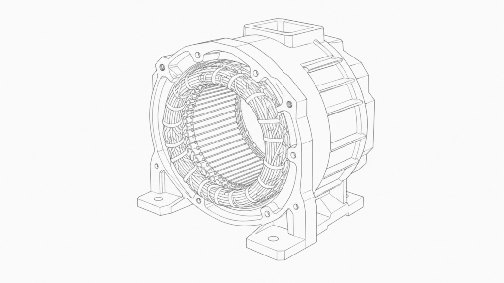
Before the motor shaft moves even a fraction of a degree, the stator windings create a magnetic field that sweeps around the inside of the motor. The rotor reacts to that moving field and attempts to follow it. That is the basic idea behind the operation of a three-phase AC motor.
Simple in principle. Slightly trickier once currents, poles and phase angles enter the picture.
Let’s slow it down and look at what is really happening.
The Stator Is More Than a Metal Cylinder
The stator is the stationary outer section of an AC motor. It is built around a cylindrical iron core containing slots. Insulated copper conductors are placed into these slots to form the stator windings.
Those windings are not installed randomly.
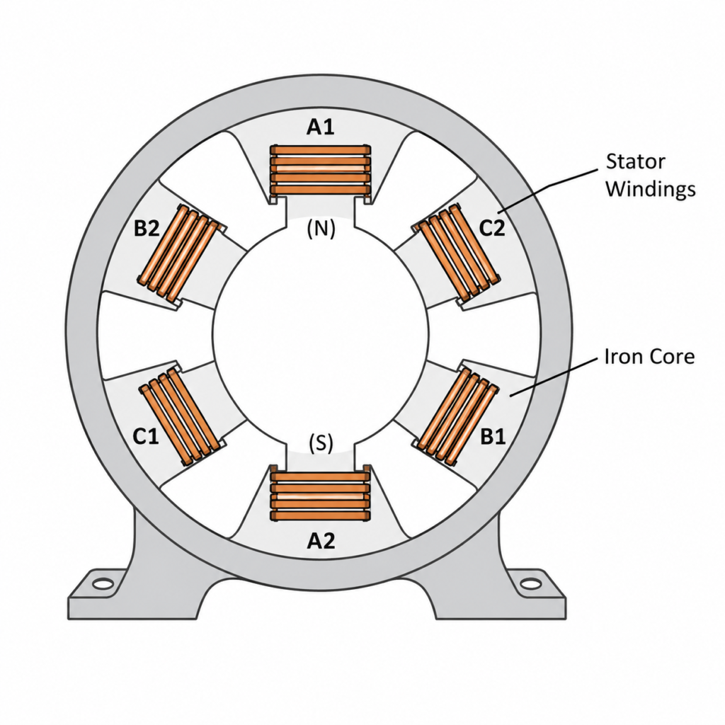
In a three-phase motor, the windings are divided into three groups:
- Phase A
- Phase B
- Phase C
Each winding group becomes an electromagnet whenever current flows through it.
A simplified two-pole motor may be shown with six individual coil sections:
- A1 and A2
- B1 and B2
- C1 and C2
The two coils belonging to each phase operate as a pair. They are positioned on opposite sides of the stator and wound so that one side becomes a north magnetic pole while the opposite side becomes a south magnetic pole.
Suppose current flows through the phase A winding in one direction. A1 may become a north pole while A2 becomes a south pole.
Reverse the current, and the poles swap:
- A1 becomes south
- A2 becomes north
Nothing physically moved. Only the direction of current changed, yet the magnetic polarity reversed completely.
That detail is important because alternating current is constantly changing direction.
Why Three Phases Are Needed
A single AC winding can create a magnetic field, but the field mainly grows, collapses and reverses direction. On its own, it does not produce the same smooth rotating field created by a balanced three-phase supply.
Three-phase power changes the situation.
The three stator windings are physically placed 120 electrical degrees apart. Meanwhile, the currents supplied to phases A, B and C are also separated in time by 120 electrical degrees.
In other words, the windings are spaced around the stator, and their currents reach their positive and negative peaks at different moments.
Phase A reaches its peak first. Phase B follows. Then phase C. The pattern continues over and over again.
That combination of physical spacing and electrical timing is the clever bit. Each winding produces its own changing magnetic field, but the three fields combine into one magnetic field that appears to rotate continuously around the stator.
No brushes are pushing it around. There is no mechanical distributor switching magnets one by one. The rotation is created entirely by the changing three-phase currents.
Understanding the Coil Arrangement
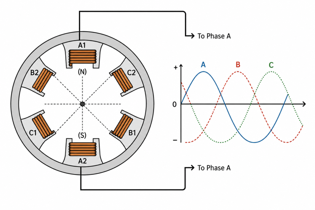
Imagine looking directly into the end of a simple two-pole stator.
The phase windings are arranged around its circumference. A1 is positioned opposite A2, B1 opposite B2, and C1 opposite C2.
For explanation purposes, we can use the following rule:
- Positive current through a “1” winding creates a north pole
- Its paired “2” winding becomes a south pole
- Negative current reverses both poles
This is only a simplified reference convention. The actual north and south poles depend on how the conductors are wound and connected.
What matters is that reversing the current reverses the magnetic field.
Because the current in every phase is continuously rising, falling and changing direction, the strength and polarity of each phase’s magnetic field are also continuously changing.
It sounds like a mess when described coil by coil. Put the three fields together, though, and something remarkably orderly appears: a rotating magnetic field.
Starting at One Instant in Time
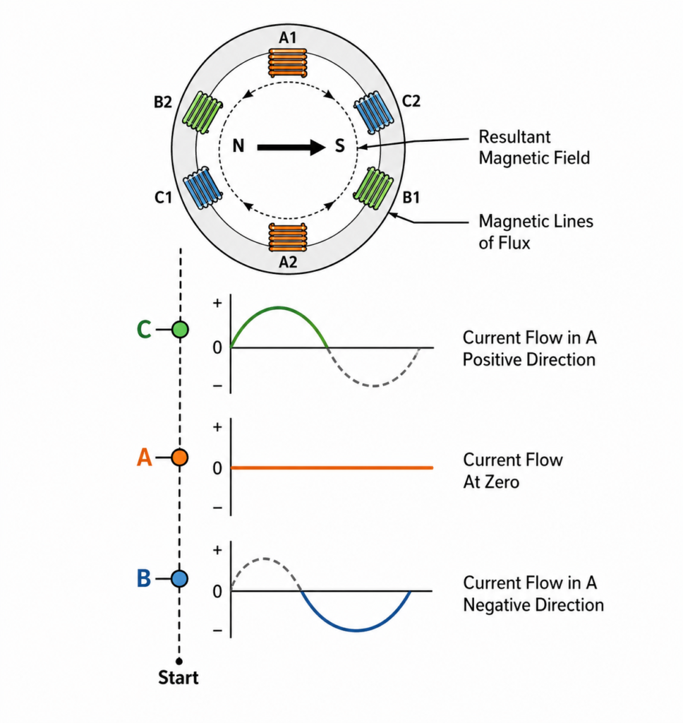
To make the process easier to visualize, let’s freeze the three-phase waveforms at a carefully selected starting point.
At this instant:
- Phase A current is zero
- Phase B current is flowing in the negative direction
- Phase C current is flowing in the positive direction
Since phase A has no current at that exact moment, it contributes no significant magnetic field.
Phase B and phase C are active.
Using our simplified polarity rule:
- B1 becomes a south pole
- B2 becomes a north pole
- C1 becomes a north pole
- C2 becomes a south pole
Magnetic flux leaves the north poles and travels toward the nearest south poles.
Flux leaves B2 and moves toward C2. At the same time, flux leaves C1 and moves toward B1.
The combined result is one magnetic field pointing in a particular direction across the stator.
That is our starting position.
Sixty Electrical Degrees Later
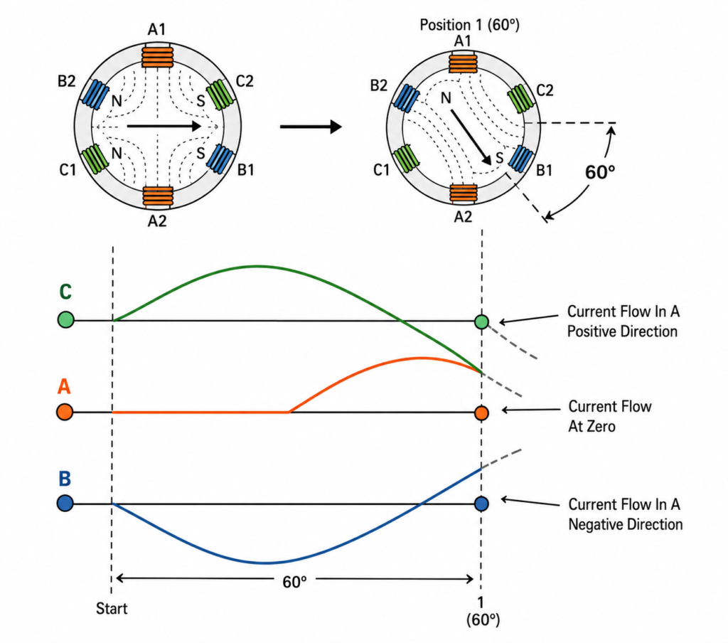
Now move forward by 60 electrical degrees.
The currents have changed:
- Phase C current is now zero
- Phase A current is positive
- Phase B current remains negative
Phase C is temporarily contributing almost nothing. Phases A and B now determine the main direction of the magnetic field.
Under these conditions:
- A1 becomes north
- A2 becomes south
- B1 remains south
- B2 remains north
When the magnetic fields from phases A and B combine, the overall field points in a new direction.
Compared with the starting position, it has moved by approximately 60 degrees around the stator.
The iron has not turned. The windings have not shifted. The electrical currents simply changed value, and the combined magnetic field moved with them.
Another Sixty Degrees Later
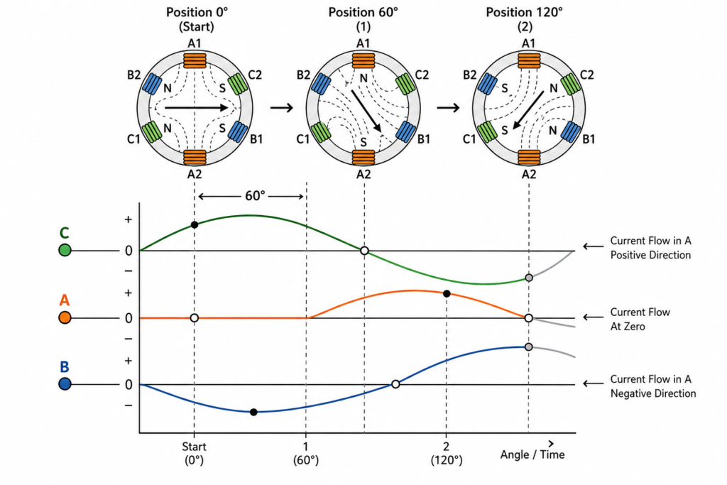
Move forward by another 60 electrical degrees.
Now:
- Phase B current is zero
- Phase A current is still positive, although it is beginning to decrease
- Phase C current has become negative
Earlier, phase C current flowed in the positive direction. It has now crossed zero and reversed.
Because its current direction changed, the north and south poles produced by the phase C winding also reverse.
The combined magnetic field advances another 60 degrees.
Continue taking these snapshots and the pattern becomes obvious. After six 60-degree intervals, the magnetic field has completed a full 360-degree rotation.
Then the electrical cycle begins again.
Of course, a real motor does not jump from one fixed magnetic position to another. The currents are sinusoidal and change continuously, so the resulting field also moves continuously. The 60-degree snapshots are merely a convenient way to understand the process.
In reality, the field sweeps smoothly around the stator.
Why the Magnetic Field Keeps Rotating
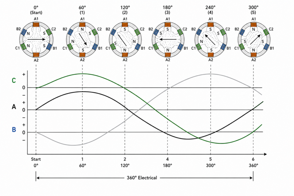
The rotating field exists because of two conditions working together:
- The three stator windings are positioned 120 electrical degrees apart.
- The three supply currents are also displaced by 120 electrical degrees.
Remove either condition and the result changes.
If all three windings were installed in the same physical position, their magnetic fields would not produce useful rotation.
If all three currents rose and fell at exactly the same time, the field would pulse rather than travel correctly around the stator.
The geometry and timing must work together. This is why proper phase sequence and correct winding placement matter so much.
It is also why swapping any two incoming phases reverses a three-phase motor.
Changing two phases changes the phase sequence. Instead of the magnetic field progressing A-B-C, it may progress A-C-B. The field rotates in the opposite direction, and the rotor follows.
A surprisingly small wiring change can reverse a very large motor.
What Is Synchronous Speed?
The speed of the rotating stator magnetic field is known as synchronous speed.
It is represented by the symbol:
Ns
Synchronous speed depends on two things:
- Supply frequency
- Number of motor poles
The formula is:
Ns = 120 × f ÷ P
Where:
- Ns = synchronous speed in revolutions per minute
- f = supply frequency in hertz
- P = number of poles
For example, consider a two-pole motor connected to a 60 Hz supply:
Ns = 120 × 60 ÷ 2
Ns = 3,600 RPM
On a 50 Hz supply, which is standard across most of Europe, the same two-pole field rotates at:
Ns = 120 × 50 ÷ 2
Ns = 3,000 RPM
Frequency matters, but pole count matters just as much.
Synchronous Speed at 50 Hz and 60 Hz
| Number of poles | Synchronous speed at 50 Hz | Synchronous speed at 60 Hz |
|---|---|---|
| 2 | 3,000 RPM | 3,600 RPM |
| 4 | 1,500 RPM | 1,800 RPM |
| 6 | 1,000 RPM | 1,200 RPM |
| 8 | 750 RPM | 900 RPM |
| 10 | 600 RPM | 720 RPM |
| 12 | 500 RPM | 600 RPM |
As the number of poles increases, synchronous speed decreases.
A two-pole motor therefore has a much faster rotating field than an eight-pole motor running from the same power supply.
This is why motor pole count is selected according to the speed required by the machine. Fans, pumps, conveyors, compressors and mixers do not all need to run at the same speed.
How the Number of Poles Is Determined
A phase winding can appear more than once around the stator.
In a simple two-pole arrangement, each phase creates one north pole and one south pole. The complete magnetic pattern contains two poles.
If the winding arrangement creates two north poles and two south poles, the motor has four poles.
Add more repeated winding groups and the number of poles increases further.
The motor does not gain poles because the power supply has changed. Pole count is mainly determined by the physical design and connection of the stator windings.
Some motors, known as pole-changing motors, can reconnect their windings to produce different pole counts. This allows them to operate at more than one approximate speed without a variable-frequency drive. They still appear in industrial installations, although VFD control is much more flexible.
Does the Rotor Turn at Synchronous Speed?
Usually, no.
In a standard induction motor, the rotor must rotate slightly slower than the stator’s magnetic field. This difference in speed is called slip.
Slip allows the rotating magnetic field to cut across the rotor conductors and induce current in them. That induced rotor current creates its own magnetic field. The interaction between the stator field and rotor field produces torque.
If the rotor somehow reached exactly the same speed as the rotating magnetic field, there would be no relative movement between them. With no relative movement, very little voltage would be induced in the rotor, rotor current would fall and the motor would no longer produce the torque needed to maintain that condition.
So a four-pole, 50 Hz induction motor has a synchronous speed of 1,500 RPM, but its actual nameplate speed may be approximately:
- 1,480 RPM
- 1,460 RPM
- 1,440 RPM
The exact speed depends on the motor design and mechanical load.
When load increases, the rotor slows slightly. Slip increases, more rotor current is induced and the motor develops additional torque.
The motor is constantly balancing itself in this way.
Synchronous Speed Is Not Nameplate Speed
This point catches people out fairly often.
The value calculated using the synchronous-speed formula is the speed of the magnetic field, not necessarily the actual shaft speed.
For an induction motor:
Rotor speed is lower than synchronous speed.
For a synchronous motor, the rotor can lock onto the rotating field and run at synchronous speed. That is a different operating principle, even though the stator still produces a rotating magnetic field.
When identifying a motor from its nameplate, the rated RPM can usually give a strong clue about the pole count.
For example, on a 50 Hz system:
- Around 2,900 RPM usually indicates a two-pole motor
- Around 1,450 RPM usually indicates a four-pole motor
- Around 960 RPM usually indicates a six-pole motor
- Around 720 RPM usually indicates an eight-pole motor
Those values vary with motor size, load and efficiency, but the pattern is easy to recognize once you know what to look for.
What Happens When Frequency Changes?
Because frequency appears directly in the synchronous-speed formula, changing frequency changes the speed of the rotating magnetic field.
This is the foundation of variable-frequency drive control.
A VFD converts the incoming power and supplies the motor with an adjustable output frequency. Lower the frequency and the magnetic field rotates more slowly. Raise it and the field rotates faster.
For a four-pole motor:
- At 50 Hz, synchronous speed is 1,500 RPM
- At 40 Hz, synchronous speed is 1,200 RPM
- At 25 Hz, synchronous speed is 750 RPM
The actual rotor speed remains slightly below these values because of slip.
A VFD also has to manage motor voltage correctly. Frequency cannot always be changed carelessly while leaving everything else untouched. Magnetic flux, cooling, torque requirements and motor insulation all need to be considered.
Still, the central idea is straightforward: control the frequency and you control the speed of the rotating magnetic field.
Why This Matters in Real Troubleshooting
Understanding the rotating field is not just electrical theory for an exam. It explains several common situations found in workshops and factories.
The motor rotates in the wrong direction
The phase sequence is incorrect. Swap any two supply phases and the rotating field reverses.
The motor hums but does not start
One phase may be missing, leaving the motor unable to produce a proper balanced rotating field. Mechanical jamming, low voltage or damaged windings may cause similar symptoms.
The motor overheats
A voltage imbalance, current imbalance or partial winding problem can distort the magnetic field. The motor may continue running, but with poor torque and increased heating.
The motor runs slower after VFD changes
The output frequency may have been reduced, intentionally or accidentally. Lower frequency means lower synchronous speed.
The replacement motor is too fast
The new motor may have fewer poles than the original. A two-pole motor and a four-pole motor connected to the same supply will run at very different speeds.
Without understanding the field, these faults can feel like unrelated problems. They are not. Many of them lead back to phase sequence, winding condition, frequency or pole count.
The Whole Process in Plain Language
A three-phase power supply sends three alternating currents into three groups of stator windings.
Those currents do not reach their peaks at the same time. Each is shifted by 120 electrical degrees.
The windings are also arranged around the stator at corresponding electrical angles.
As the currents rise, fall and reverse, each winding repeatedly changes its magnetic strength and polarity. The three magnetic fields combine into one field that rotates around the stator bore.
The rotor experiences that moving field and develops torque.
That is how stationary copper windings produce mechanical rotation without physically moving themselves.
A bit strange when you first picture it. Beautifully logical once it clicks.
Final Thoughts
The rotating magnetic field is one of the most important ideas in AC motor theory.
It explains why three-phase motors start naturally, why swapping two phases changes direction, why pole count affects speed and why VFDs can control motor RPM by changing frequency.
The stator does not physically rotate, yet the magnetic pattern inside it does. The rotor follows that pattern, producing the shaft rotation used to drive pumps, fans, conveyors and countless other machines.
So the next time a motor starts and immediately settles into a steady hum, remember what is happening inside it: three currents, separated in time, producing a magnetic field that races around the stator thousands of times per minute.
No mechanical switching. No visible movement in the windings.
Just electromagnetism doing the heavy lifting.