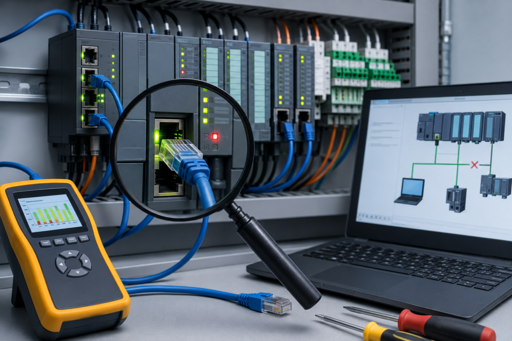
Old control panels were forests of wire.
Every push button, limit switch, solenoid and motor feedback contact needed its own conductor running back to the PLC cabinet. Add a few dozen field devices and the cable trays filled up remarkably fast. Troubleshooting usually meant tracing numbered wires through terminal strips while hoping the electrical drawings had actually been updated.
Industrial networks changed that.
A single communication cable can now carry status information and commands for remote I/O stations, drives, valve manifolds, weighing systems, energy meters and dozens of other devices. It saves wiring, makes diagnostics more useful and allows far more data to move around the machine.
When it works, it is brilliant.
When it does not, one damaged connector can make half a production line disappear at once.
That is why maintenance technicians do not necessarily need to memorize every byte of every protocol, but they should understand the basic architecture. Is the network arranged as a trunk with short branches? Does it require termination? Are device addresses unique? Does the communication cable also carry power? Which settings must match?
Those details often tell you where to begin.
This guide focuses on three protocols still commonly encountered in industrial installations:
- DeviceNet
- PROFIBUS DP
- Modbus RTU and Modbus TCP
Some are older than others, but older does not mean gone. Plenty of factories continue running equipment designed ten, twenty or even thirty years ago. Production managers rarely replace a working machine merely because its network protocol is no longer fashionable.
Why Industrial Communication Protocols Matter
A communication network allows multiple devices to exchange information over a shared connection.
Instead of running separate wires for every signal, a PLC may communicate with a remote I/O rack using one network cable. That remote rack then connects locally to nearby sensors and actuators.
The same network may also carry information such as:
- Motor speed
- Drive current
- Fault codes
- Temperature
- Pressure
- Valve position
- Energy consumption
- Device diagnostics
- Maintenance warnings
- Production counters
A hardwired signal often tells the PLC only whether something is ON or OFF.
A networked drive can tell the PLC that it has stopped because of overcurrent, motor overload, undervoltage or communication loss. That extra detail makes troubleshooting much faster—provided the network itself is healthy.
When communication fails, the cause usually falls into one of several groups:
- Physical wiring problem
- Power-supply problem
- Incorrect addressing
- Missing termination
- Mismatched communication parameters
- Configuration error
- Electrical noise
- Failed device
- Controller programming problem
The trick is determining which group you are dealing with before parts start being swapped at random.
DeviceNet
What Is DeviceNet?
DeviceNet is an industrial network based on CAN, or Controller Area Network.
CAN technology is also widely used in vehicles, although the higher-level communication rules are different. In an industrial setting, DeviceNet was commonly used to connect PLCs with:
- Distributed I/O
- Motor starters
- Variable-frequency drives
- Photoelectric sensors
- Valve manifolds
- Operator stations
- Safety devices
- Barcode readers
DeviceNet became particularly common in Rockwell Automation and Allen-Bradley installations.
It is no longer the first choice for many new systems, where EtherNet/IP has largely taken over, but there are still a great many DeviceNet machines in service.
And they still need fixing.
DeviceNet Trunk-and-Drop Wiring
A typical DeviceNet installation uses a trunk-and-drop arrangement.
Think of it like a tree.
The main trunk cable travels through the machine or production area. Shorter drop cables branch from the trunk and connect individual devices.
A standard DeviceNet cable contains five conductors:
- Two communication conductors
- Two network-power conductors
- One shield or drain conductor
The traditional colour convention is:
- Blue: CAN low
- White: CAN high
- Black: 0 V
- Red: positive network supply
- Bare or shielded conductor: drain
The network commonly distributes 24 V DC power along with communication, although actual voltage at the devices must remain within the permitted range.
This combined power-and-data arrangement is convenient, but it also creates an important troubleshooting lesson:
A DeviceNet fault may be a communication problem, a power problem or both.
DeviceNet Node Addresses
Each DeviceNet device requires a unique node address, usually called a MAC ID.
Valid addresses range from:
0 to 63
The scanner is often assigned address 0, although that is a convention rather than an absolute rule. Field devices use the remaining unique addresses.
If a replacement device is installed with the same address as an existing device, communication conflicts occur.
Symptoms may include:
- Scanner faults
- Device repeatedly appearing and disappearing
- Duplicate node warnings
- One or more devices remaining offline
- Network scan failures
- Red status LEDs
A duplicate address does not always destroy every part of the network, but it can certainly disrupt communication and make the scanner configuration unusable until the conflict is corrected.
Whenever a DeviceNet component is replaced, check its node address before connecting it to the live network.
DeviceNet Baud Rate
All devices must use a compatible communication speed.
Common DeviceNet baud rates include:
- 125 kbit/s
- 250 kbit/s
- 500 kbit/s
Higher speeds permit shorter maximum trunk lengths.
A newly installed device using the wrong baud rate may fail to join the network even when its node address is correct.
Some devices use automatic baud detection. Others rely on DIP switches, rotary switches or software configuration.
Always inspect both.
DeviceNet Termination
DeviceNet requires one terminating resistor at each physical end of the trunk.
The nominal value is:
121 ohms
Only two terminators should be installed—one at each end of the main trunk.
Not on every device.
Not at each drop.
And not halfway down the cable because the spare resistor happened to fit there nicely.
With the network power removed, a resistance measurement taken across the CAN communication conductors often reads approximately:
60 ohms
That value comes from the two 121-ohm terminating resistors connected in parallel.
A reading close to 120 ohms may indicate that one terminator is missing.
A much lower value may indicate extra terminators or another parallel resistance path.
This test is useful, but power must be isolated and the measurement interpreted carefully. Connected equipment can affect resistance readings.
Common DeviceNet Problems
Damaged drop cables
Drop cables are frequent failure points because they are often routed close to moving equipment, motors and field devices.
Check for:
- Crushed cable
- Broken connector
- Loose coupling
- Coolant contamination
- Cable tension
- Repeated bending
- Damaged shielding
A branch serving one device may fail while the remainder of the trunk continues operating.
Low network voltage
The DeviceNet supply may measure 24 V DC at the power supply and considerably less at the far end of the trunk.
Voltage drop depends on:
- Cable length
- Conductor size
- Total device current
- Connection resistance
- Number of taps
- Power-injection location
Measure voltage at the affected device while the network is operating.
A marginal supply may allow devices to start, then disconnect when additional loads turn on.
Missing or incorrect termination
A missing terminator can cause signal reflections and intermittent communication errors.
Problems may become worse with:
- Longer cable runs
- Higher baud rates
- Electrical noise
- Larger networks
Duplicate node addresses
This often occurs after component replacement or when someone connects a factory-default device without checking its settings.
Incorrect baud rate
The device may have the correct address but still remain invisible because it is communicating at a different speed.
Poor shielding or grounding
Improper shield connections can increase susceptibility to electrical interference, especially near VFD output cables or large contactors.
Excessive trunk or drop length
DeviceNet cable-length rules depend on baud rate and cable type.
A network that was marginal from the beginning may become unstable after an extra device or cable extension is added.
Reading DeviceNet Status LEDs
Many DeviceNet devices provide separate indicators for module status and network status.
Exact colours and flashing patterns vary, but a common arrangement includes:
- Solid green: operating normally
- Flashing green: online but not fully connected
- Solid red: serious or unrecoverable fault
- Flashing red: recoverable fault or connection timeout
- Alternating red and green: self-test or special fault condition
Do not diagnose from colour alone.
Read the device manual because one flashing red LED can mean something very different from another flashing red LED.
DeviceNet Troubleshooting Workflow
When DeviceNet communication fails:
- Check network power at the affected device.
- Inspect scanner and device LEDs.
- Check connectors and drop cables.
- Confirm the node address.
- Confirm the baud rate.
- Check that both trunk terminators are present.
- Measure network resistance with power removed.
- Compare the scanner configuration with the real devices.
- Look for recently replaced equipment.
- Use network software to identify offline or mismatched nodes.
For Rockwell systems, RSNetWorx for DeviceNet may be used to scan the network, configure devices and inspect the scanner’s node list.
Older software is not always pleasant, but it remains extremely useful on machines built around it.
PROFIBUS DP
What Is PROFIBUS?
PROFIBUS is a family of industrial communication technologies.
The version most technicians encounter in factory automation is:
PROFIBUS DP
DP stands for Decentralized Peripherals. It was designed for fast communication between a controller and distributed devices such as:
- Remote I/O
- Drives
- Valve manifolds
- Encoders
- Weighing modules
- Operator panels
- Intelligent sensors
PROFIBUS DP is strongly associated with Siemens equipment, but many other manufacturers support it.
It is especially common across Europe, although you can find it almost anywhere industrial automation has been installed.
PROFIBUS Cable and Topology
PROFIBUS DP usually uses shielded twisted-pair RS-485 cable.
The cable is commonly purple, which makes it easy to identify in a cabinet—assuming nobody used the nearest available cable during an emergency repair years ago.
Devices are generally connected in a bus, or daisy-chain, arrangement.
The cable enters one connector and continues from that connector to the next device.
Long star branches are normally avoided unless approved repeaters or active components are used.
The physical bus has two ends, and both ends must be terminated.
PROFIBUS Addresses
Each device requires a unique station address.
The address range extends from:
0 to 126
In practice, certain addresses may be reserved or used by convention. Address 126 is commonly used as a default commissioning address on some equipment and should not normally be left duplicated on an operating bus.
The PLC or communication processor is typically the controller, while remote devices are assigned individual addresses.
Duplicate station addresses can prevent communication and create confusing bus faults.
Before replacing a device, record:
- Existing station address
- Device type
- Configuration file
- Communication speed
- Connector position
- Termination-switch position
A photograph before removal can save a surprising amount of trouble.
PROFIBUS Termination
PROFIBUS requires termination at both physical ends of each bus segment.
Many PROFIBUS connectors include a small termination switch.
The usual arrangement is:
- First device: termination ON
- Intermediate devices: termination OFF
- Last device: termination ON
A common mistake is leaving termination enabled on an intermediate device.
Another is replacing the last device and forgetting to switch termination on.
There is one slightly awkward detail: some connector-based termination circuits rely on power from the connected device. If the terminating device is powered down, the termination may disappear and disturb the entire bus.
For installations where the end device may be switched off independently, an active terminator may be more suitable.
Common PROFIBUS Problems
Poorly installed connectors
PROFIBUS connectors are one of the first places to look.
Possible issues include:
- Conductors not fully inserted
- Shield not clamped correctly
- Insulation trapped in terminals
- Cable entering the wrong side
- Termination switch set incorrectly
- Connector screws loose
- Corrosion
- Broken internal contacts
Some connectors use insulation-displacement contacts. They must be fitted correctly to the specified cable.
A connector can look perfectly normal from the outside while making a dreadful connection inside.
Termination faults
Missing, extra or unpowered termination can cause:
- Intermittent bus faults
- Devices dropping offline
- Errors that worsen at higher speeds
- Communication failure after one device is switched off
- Reflections visible during signal analysis
Damaged cable
PROFIBUS is sensitive to cable quality and installation.
Check for:
- Crushed sections
- Tight bends
- Excessive stripping
- Poor shield continuity
- Improvised joints
- Long unapproved branches
- Cable run beside high-power conductors
- Movement-related fatigue
Shielding and grounding problems
The cable shield should be bonded according to the equipment and installation requirements.
Poor shield connections may allow electrical noise to disturb communication.
This is especially likely when the cable runs near:
- VFD output cables
- Servo motor cables
- Welding equipment
- Large contactors
- High-current busbars
Duplicate addresses
A replacement drive or remote I/O adapter may retain a default address that conflicts with another node.
Incorrect hardware configuration
Even with the correct address, the PLC may reject a device if its configured module layout does not match the real hardware.
For example:
- Wrong I/O module order
- Incorrect module type
- Missing option card
- Wrong device version
- Incorrect GSD file
- Different data length
Excessive cable length
Maximum segment length decreases as baud rate increases.
A bus that works at a lower communication speed may become unstable when the speed is raised without reviewing the cable layout.
PROFIBUS BF and SF LEDs
Siemens equipment commonly uses indicators such as:
- BF: Bus Fault
- SF: System Fault
A BF LED generally points toward a network or communication problem.
Possible causes include:
- Cable disconnected
- Wrong station address
- Missing device
- Termination problem
- Configuration mismatch
- Failed communication interface
An SF LED indicates a system or diagnostic fault, which may relate to configuration, I/O channels or another module condition.
The LEDs provide direction, not a complete diagnosis.
Open the PLC diagnostic buffer and the device diagnostics to see what the controller actually detected.
PROFIBUS Troubleshooting Workflow
When a PROFIBUS network fails:
- Observe BF and SF LEDs.
- Identify whether one device or the whole segment is affected.
- Check power at the missing device.
- Inspect both PROFIBUS connectors.
- Confirm the station address.
- Check termination at both physical ends.
- Verify that intermediate termination switches are off.
- Compare the installed device with the PLC hardware configuration.
- Check cable shielding and grounding.
- Inspect routing near motors and VFD cables.
- Review diagnostic-buffer timestamps.
- Use a bus analyser for persistent intermittent faults.
If touching or moving one connector changes the fault, that is a fairly blunt clue. Replace or reterminate it instead of trying to position it at the one angle where the machine behaves.
Modbus
Why Modbus Is Still Everywhere
Modbus has been around since the late 1970s and remains one of the most widely supported industrial protocols.
It appears in:
- PLCs
- HMIs
- VFDs
- Energy meters
- Temperature controllers
- Power analysers
- Flowmeters
- Building-management systems
- Remote I/O
- Instruments
- Gateways
Its longevity comes partly from its simplicity.
A device requests data from another device by referring to register or coil addresses. The responding device returns the requested value or an exception code.
It is not particularly glamorous. It simply works—until one register offset ruins your afternoon.
Modbus RTU and Modbus TCP
The two versions most commonly encountered are:
- Modbus RTU
- Modbus TCP
They share much of the same data model but use different transport methods.
Modbus RTU
Modbus RTU commonly runs over an RS-485 serial network.
Devices share a twisted-pair communication cable and are normally arranged in a bus topology.
One device acts as the client and sends requests. Server devices respond when addressed.
Older documentation often uses the terms “master” and “slave.” Modern documentation increasingly uses “client” and “server.” You will still encounter both word sets on older equipment and in existing PLC programs.
Modbus TCP
Modbus TCP operates over standard Ethernet and TCP/IP networks.
Devices use IP addresses rather than only serial node addresses.
The standard Modbus TCP port is:
TCP port 502
The network may use switches, routers and standard industrial Ethernet infrastructure.
How Modbus Communication Works
A Modbus client sends a request containing information such as:
- Target device
- Function code
- Starting address
- Number of values requested
- Data to be written, where applicable
The server processes the request and sends a response.
The client controls the conversation.
A normal server generally does not send unsolicited Modbus RTU replies. It waits until it is polled.
This makes the communication structure fairly straightforward, but it also means the polling interval and timeout settings matter.
Modbus RTU Device Addresses
Modbus RTU server addresses generally range from:
1 to 247
Address 0 is commonly used for broadcast messages. A device receiving a broadcast may act on it but does not send a normal reply.
Every server on the same serial segment must have a unique address.
Duplicate addresses can produce:
- Corrupted responses
- CRC errors
- Timeouts
- Replies from the wrong device
- Completely unreliable data
Modbus RTU Communication Settings
Every device on the serial network must agree on settings such as:
- Baud rate
- Parity
- Number of data bits
- Number of stop bits
Common baud rates include:
- 9,600
- 19,200
- 38,400
- 57,600
- 115,200
A common configuration might be:
- 9,600 baud
- 8 data bits
- Even parity
- 1 stop bit
Another device may default to:
- 19,200 baud
- 8 data bits
- No parity
- 2 stop bits
Those devices will not communicate until the settings match.
This is one of the first things to check in a Modbus RTU fault.
Modbus RTU RS-485 Wiring
A two-wire RS-485 network normally uses a differential pair.
Manufacturers label the conductors in several different ways:
- A and B
- D+ and D−
- Data+ and Data−
- TX/RX+ and TX/RX−
Unfortunately, A and B labelling is not perfectly consistent between manufacturers.
One manufacturer’s A may correspond to another manufacturer’s B. Never connect solely by matching letters without checking the manuals.
If there is no communication, reversed polarity is a very reasonable suspicion.
A reference conductor or signal common may also be required, depending on the equipment and network design.
Modbus RTU Termination and Biasing
Long or high-speed RS-485 networks may require terminating resistors at both physical ends of the bus.
A typical terminating value is approximately:
120 ohms
Intermediate devices should not normally be terminated.
Bias resistors may also be used to hold the line in a known idle state when no device is transmitting.
Incorrect or excessive termination can weaken the signal. Missing termination can cause reflections.
Short, low-speed networks sometimes work without textbook-perfect termination, which is why poorly installed systems can survive for years and then become unstable after one innocent-looking change.
Modbus Registers and Coils
Modbus devices expose several logical data areas.
Common categories include:
- Coils
- Discrete inputs
- Input registers
- Holding registers
Typical function codes include:
- 01: Read coils
- 02: Read discrete inputs
- 03: Read holding registers
- 04: Read input registers
- 05: Write single coil
- 06: Write single register
- 15: Write multiple coils
- 16: Write multiple registers
Not every device supports every function.
The device manual should state which addresses and function codes are available.
The Modbus Address Offset Problem
One of the most common Modbus problems is register numbering.
A manual may show a holding register as:
40001
The PLC instruction may expect:
- 0
- 1
- 40001
- 400001
It depends on the software and manufacturer.
Some systems use zero-based addressing, while documentation may use one-based reference numbers.
This creates the classic off-by-one problem.
You request register 100, but the value you actually need is located at protocol address 99.
When communication is successful but the returned value makes no sense, check the address convention before blaming the instrument.
Modbus Data Types and Byte Order
A Modbus register is normally 16 bits.
Larger values may use multiple registers.
Examples include:
- 32-bit integer
- 32-bit floating-point value
- 64-bit value
- Character string
Manufacturers may store words in different orders.
A 32-bit value can therefore appear with:
- Normal word order
- Swapped word order
- Swapped bytes
- Both bytes and words swapped
Symptoms include:
- Huge unrealistic numbers
- Negative values where only positive values are expected
- Floating-point values close to zero
- Values that change but remain meaningless
When the correct registers are being read but the number is nonsense, check:
- Data type
- Signed or unsigned interpretation
- Scaling
- Decimal position
- Word order
- Byte order
The network may be working perfectly. The data may simply be interpreted incorrectly.
Modbus Timing Problems
A client sends a request and waits for a response.
If the timeout is too short, a slow server may respond after the client has already given up.
Problems may also occur when:
- Requests are sent too quickly
- Several clients poll the same serial server
- There is insufficient silent time between RTU frames
- A gateway is overloaded
- The serial baud rate is low
- Too many registers are requested at once
Symptoms include:
- Random timeout errors
- Communication that improves when polling is slowed
- Some devices working while others fail
- Errors only during heavy network activity
Increasing the timeout may help, but do not turn a two-second problem into a thirty-second wait without investigating why the device is slow.
Common Modbus RTU Problems
Mismatched serial settings
Baud rate, parity and stop-bit settings must match.
Reversed RS-485 polarity
Swap the differential pair as a controlled test after checking documentation.
Duplicate server addresses
Each device needs a unique ID.
Missing common reference
Some installations need a signal reference conductor to keep common-mode voltage within acceptable limits.
Incorrect termination
Use termination only where required and only at the segment ends.
Star wiring
RS-485 generally prefers a bus arrangement. Large star branches can create reflections and unstable communication.
Incorrect register number
Check whether the software expects zero-based or one-based addressing.
Wrong function code
A device may allow a value to be read as an input register but not as a holding register.
Wrong data format
Confirm scaling, signedness and word order.
Common Modbus TCP Problems
Incorrect IP configuration
Check:
- IP address
- Subnet mask
- Gateway
- Duplicate IP addresses
TCP port blocked
Modbus TCP normally uses port 502. A firewall, router or security appliance may block it.
Device limit exceeded
Some Modbus TCP servers support only a limited number of simultaneous client connections.
Wrong unit identifier
The unit identifier may be important when Modbus TCP traffic passes through a gateway to serial devices.
Register mapping mismatch
Ethernet communication may be healthy while the requested register or data type is incorrect.
Excessive polling
A small instrument may not cope well with hundreds of requests per second.
Testing Modbus Communication
A simple Modbus client utility is extremely useful.
It allows a laptop to request registers directly from a device without involving the PLC program.
For Modbus RTU, connect using an appropriate USB-to-RS-485 converter and configure:
- COM port
- Baud rate
- Parity
- Stop bits
- Device address
For Modbus TCP, configure:
- Device IP address
- TCP port
- Unit identifier, if required
Then request a known register.
Choose something easy to verify, such as:
- Device status
- Frequency
- Voltage
- Temperature
- Product identification
Be cautious when testing write functions. Writing the wrong register can start equipment, change calibration or alter communication parameters.
Reading is normally the safer place to begin.
DeviceNet, PROFIBUS and Modbus Compared
| Feature | DeviceNet | PROFIBUS DP | Modbus RTU | Modbus TCP |
|---|---|---|---|---|
| Physical basis | CAN | RS-485 | Usually RS-485 | Ethernet |
| Common topology | Trunk and drop | Bus or daisy-chain | Bus or daisy-chain | Switched Ethernet |
| Device addressing | MAC ID 0–63 | Station address 0–126 | Server ID 1–247 | IP address |
| Network power | Commonly carried in cable | Normally separate | Normally separate | Normally separate |
| Termination | 121 ohms at trunk ends | At both segment ends | Often 120 ohms at bus ends | Not RS-485 termination |
| Common software association | Rockwell systems | Siemens and European systems | Almost every manufacturer | Almost every manufacturer |
| Frequent problems | Power, drops, addressing, termination | Connectors, termination, shielding, configuration | Serial settings, polarity, addresses, register mapping | IP settings, port 502, connection limits, register mapping |
A General Industrial Communication Troubleshooting Method
The protocols differ, but the troubleshooting logic is remarkably similar.
1. Define the Scope
First determine what is affected.
Ask:
- Is one device offline?
- Is one branch affected?
- Is the entire network down?
- Did the fault appear after a replacement?
- Is communication intermittent?
- Does it fail when a motor starts?
- Does it work until one particular device is powered?
If one DeviceNet drop is affected, look locally.
If every PROFIBUS station disappears at once, inspect the controller, trunk cable and termination before replacing six remote devices.
2. Check Device Power
A field device cannot communicate without stable power.
Measure voltage at the device terminals.
Do not assume it is powered because one LED flashes briefly.
Look for:
- Low 24 V DC
- Loose terminal
- Blown fuse
- Overloaded power supply
- Voltage drop along the network
- Device repeatedly restarting
3. Inspect the Physical Network
Check:
- Cable damage
- Connector tightness
- Pin condition
- Shield connection
- Trunk continuity
- Drop cables
- Switch port
- Link LEDs
- Termination switches
Most communication failures are not exotic protocol failures.
They are ordinary physical problems in a more complicated outfit.
4. Verify Addresses
Every device must use the correct unique address.
Depending on the protocol, this may be:
- DeviceNet MAC ID
- PROFIBUS station address
- Modbus RTU server ID
- Ethernet IP address
Compare the physical settings with the PLC project.
Do not assume the number shown on the device is what the program expects.
5. Check Communication Parameters
For serial networks, confirm:
- Baud rate
- Parity
- Data bits
- Stop bits
For Ethernet networks, confirm:
- IP address
- Subnet mask
- Gateway
- Port number
For configured fieldbuses, also check:
- Device type
- Module layout
- Data length
- Configuration file
- Firmware revision
6. Confirm Termination
DeviceNet, PROFIBUS and RS-485 networks rely on correct physical termination.
Check:
- Correct resistor value
- Only two ends terminated
- No accidental intermediate terminators
- Powered termination where required
- No missing final device
A network can run badly with incorrect termination rather than failing completely. That is what makes these faults irritating.
7. Review Diagnostics
Use all available information:
- PLC diagnostic buffer
- Scanner status
- Device status LEDs
- Module error codes
- Network software
- Managed-switch diagnostics
- Communication counters
- Error history
Record the exact message before resetting anything.
8. Look for Patterns
Patterns often reveal the root cause.
Failure when a motor starts
Suspect voltage drop, grounding or electrical noise.
Failure at one machine position
Suspect a moving cable or connector.
Failure after device replacement
Suspect addressing, baud rate or configuration.
Failure after several hours
Suspect temperature, moisture or a marginal supply.
Communication improves when polling is slowed
Suspect timing, overload or a slow server device.
Entire segment fails when one device is powered down
Suspect termination or bus topology.
9. Change One Thing at a Time
Replace one cable.
Correct one address.
Move one switch port.
Then test.
Changing several items together may restore communication, but it leaves the real cause unknown.
That problem tends to return later, usually during night shift.
Quick Troubleshooting Reference
| Protocol | Start by checking | Then verify |
| DeviceNet | Network voltage, trunk and drop cables | MAC ID, baud rate and both terminators |
| PROFIBUS DP | Connectors, BF LEDs and device power | Station address, end termination and hardware configuration |
| Modbus RTU | Baud rate, parity and RS-485 polarity | Server ID, termination, register address and data type |
| Modbus TCP | Ethernet link, ping and IP settings | TCP port, unit identifier, register map and connection limits |
What About PROFINET and EtherNet/IP?
Modern machines increasingly use Ethernet-based industrial protocols such as:
- PROFINET
- EtherNet/IP
- EtherCAT
- Modbus TCP
They run over Ethernet infrastructure but are not interchangeable.
A PLC supporting EtherNet/IP cannot automatically communicate with a PROFINET device merely because both have RJ45 connectors.
The connector tells you very little about the industrial protocol being used.
Ethernet-based systems introduce their own troubleshooting areas:
- IP addressing
- Device names
- Managed switches
- VLANs
- Ring redundancy
- Multicast traffic
- Real-time performance
- Network security
- Firmware compatibility
The same basic troubleshooting principle still applies: begin with power and the physical connection, then move upward through addressing, protocol settings and PLC configuration.
Final Thoughts
Industrial networks reduce wiring and give PLC systems access to much richer information than traditional hardwired control.
They also concentrate many signals onto a shared communication path.
A loose DeviceNet drop cable may remove a motor starter. A bad PROFIBUS terminator may disturb an entire segment. One mismatched parity setting can make a Modbus instrument appear completely dead even though its wiring is perfect.
The fastest route to a solution is rarely random software experimentation.
Start with power.
Inspect the cable and connectors.
Confirm unique addresses.
Check communication parameters and termination.
Then use the diagnostic tools provided by the PLC, scanner and field devices.
You do not need to memorize every detail of every industrial protocol. Nobody sensible does. What matters is recognizing the network structure, knowing which settings must agree and troubleshooting one layer at a time.
Once you do that, the communication fault stops looking like mysterious digital magic.
Most of the time, it becomes a perfectly ordinary electrical or configuration problem—just travelling through a different kind of wire.