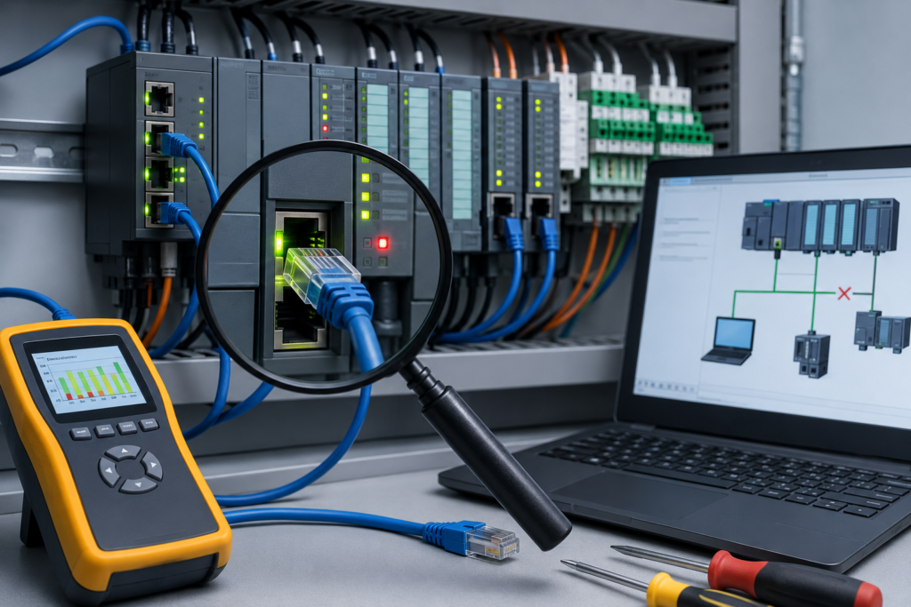
The machine stops, the operator points at the control cabinet, and somebody says the sentence every automation technician has heard:
“It must be the PLC.”
Maybe it is.
Usually, though, it is not.
A failed sensor, loose terminal, tripped overload, missing 24 V supply or damaged cable can all make a perfectly healthy PLC-controlled machine look completely dead. The controller merely reports what it sees—or, more accurately, what it does not see.
The worst response is to start swapping components at random. Replace the sensor. Restart the HMI. Download an old program. Change a timer. Swap an output module. Eventually the machine might run again, but nobody knows which action solved the problem or whether it is likely to return.
A systematic PLC troubleshooting approach is slower for the first five minutes and much faster for the next two hours.
The basic method is straightforward:
- Make the system safe.
- Understand the actual symptom.
- Check power and other basic conditions.
- Separate the field fault from the PLC fault.
- Use diagnostics and measurements to prove the cause.
- Repair one problem at a time.
- Test the machine properly.
- Document what happened.
Simple on paper. In practice, production pressure has a way of making people skip steps.
First, Do Not Assume the PLC Has Failed
PLCs are generally reliable devices.
They can fail, certainly. Power supplies age, communication ports become damaged, memory cards corrupt and input or output channels burn out. Still, complete CPU failure is less common than problems involving:
- Sensors
- Actuators
- Field wiring
- Terminal connections
- Fuses
- Contactors
- Motor overloads
- Communication cables
- Network switches
- Power supplies
- Mechanical movement
- Incorrect settings
The PLC often becomes the main suspect because it sits in the centre of the control system. Every signal passes through it, so every problem appears somewhere in the program.
That does not mean the controller caused it.
Suppose a conveyor does not start. The PLC output is OFF. That may look like a programming problem, but perhaps the controller is correctly refusing to start because an overload contact is open.
Or the output may be ON while the motor remains stopped. In that case, the PLC may be working perfectly while the fault lies in the output circuit, contactor, overload, power wiring or motor.
Before replacing anything, determine where the expected signal stops.
Step 1: Make the Machine Safe
Troubleshooting should begin with safety, not software.
A stopped machine may still contain:
- Live electrical conductors
- Stored pneumatic pressure
- Hydraulic pressure
- Suspended loads
- Rotating parts
- Hot surfaces
- Stored spring energy
- Automatic restart conditions
Follow the site’s approved safety procedures.
Depending on the task, this may include:
- Stopping the machine
- Selecting maintenance or manual mode
- Informing operators
- Clearing personnel from the area
- Applying lockout/tagout
- Isolating electrical power
- Releasing stored pressure
- Supporting raised components
- Confirming that automatic motion is prevented
Going online with the PLC and observing logic may not require full isolation in every situation. Opening wiring, changing hardware, moving actuators or forcing outputs may require much stricter controls.
Never allow production pressure to decide the safety standard.
A machine that is already stopped is inconvenient. A machine that moves unexpectedly while someone is inside it is something else entirely.
Step 2: Understand What Actually Happened
Do not begin with a vague complaint such as:
“The line is broken.”
Ask questions.
Useful questions include:
- What was the machine doing when it stopped?
- Did it stop suddenly or complete the current cycle?
- Which station stopped first?
- Was there an alarm on the HMI?
- Did any motor, valve or cylinder behave strangely?
- Has this fault happened before?
- Does it occur with a specific product or recipe?
- Was anything repaired or adjusted recently?
- Did the fault begin after a power interruption?
- Does resetting the machine temporarily restore operation?
Operators may not describe the fault using technical language, but their observations are often valuable.
Comments such as these can point directly toward the cause:
- “It only happens when the large compressor starts.”
- “The machine stops when that cable chain moves fully forward.”
- “It began after maintenance changed the sensor.”
- “The fault is worse on hot afternoons.”
- “The HMI freezes, but the motors keep running.”
Listen carefully, but verify everything.
The operator may say the PLC is not sending an output when the real problem is a missing sequence permissive. Their description is evidence, not the final diagnosis.
Step 3: Record the Initial Condition
Before resetting alarms, cycling power or clearing faults, record what the system is showing.
Check:
- PLC RUN, STOP and fault LEDs
- I/O module indicators
- Communication-module LEDs
- Remote I/O status
- Safety relay indicators
- VFD or servo fault codes
- HMI alarms
- Breaker positions
- Fuse indicators
- Motor overloads
- Power-supply LEDs
- Ethernet switch port lights
- Sensor status LEDs
Write down the exact error code.
Take photographs or screenshots where permitted.
Do not write only:
“PLC fault.”
A useful record is more specific:
CPU in RUN mode. Remote I/O adapter showing flashing red network LED. HMI alarm: “Station 4 communication lost.” Switch port 7 link light cycling on and off.
That information can still be useful after the machine has been reset.
Step 4: Check the Basics First
A surprising number of supposedly complex PLC faults are basic electrical problems.
Start with power.
Is the PLC Powered?
Check the controller and power-supply indicators.
If the PLC has no power, determine why:
- Main breaker open
- Control transformer fault
- 24 V DC power supply failed
- Fuse blown
- Loose terminal
- Emergency circuit removed control power
- Upstream contactor not energized
Measure voltage at the PLC supply terminals, not only at the power-supply output.
A wire may be loose between them.
Is the PLC in RUN Mode?
A powered controller may be in:
- RUN
- STOP
- PROGRAM
- REMOTE
- FAULT
- Maintenance mode
If the CPU is in STOP or faulted mode, outputs may not operate.
Find out why it changed mode before switching it back.
Are the I/O Modules Powered?
Some I/O modules require separate field power.
The CPU may run normally while an output module has no 24 V supply.
Check:
- Module power
- Field power
- Common terminals
- Fuses
- Removable terminal blocks
- Backplane seating
Are Any Breakers or Overloads Tripped?
A motor overload trip can prevent a PLC input permissive from becoming true.
The PLC may then refuse to start the motor even after the operator presses Start repeatedly.
Resetting the PLC will not reset a tripped motor overload.
Are Safety Circuits Healthy?
Check the actual safety system.
A standard PLC may receive a “safety healthy” signal from:
- Safety relay
- Safety PLC
- Guard controller
- Emergency-stop circuit
If that signal is missing, normal machine logic may remain inhibited.
Do not bypass safety conditions merely to prove that the machine can move.
Step 5: Decide Whether the Fault Is Input, Logic or Output Related
Most PLC troubleshooting can be divided into three areas:
- The PLC is not receiving the expected input.
- The PLC receives the input, but the program does not create the expected command.
- The PLC creates the output command, but the field device does not respond.
That simple division keeps the investigation focused.
When the PLC Is Not Receiving an Input
Suppose a proximity sensor is physically active, but the PLC input remains OFF.
Check the signal layer by layer.
1. Is the Physical Condition Really Present?
Confirm that the target is actually in front of the sensor.
A mechanical stop may have shifted, leaving the product just outside the sensing range.
2. Is the Sensor Powered?
Check the sensor LED and measure its supply.
Most industrial sensors require a stable 24 V DC supply.
3. Is the Sensor Output Switching?
A sensor LED can be on while the output transistor has failed.
Measure the output voltage.
4. Is the Signal Reaching the Input Terminal?
Trace the wiring through:
- Junction boxes
- Terminal strips
- Connectors
- Cable chains
- Remote I/O
5. Is the Input Module LED On?
If voltage reaches the input terminal but the channel LED remains off, investigate:
- Input common
- Incorrect wiring polarity
- Channel configuration
- Damaged module
- Wrong voltage level
6. Is the Correct PLC Tag Being Monitored?
Check:
- Rack
- Slot
- Channel
- Address
- Tag alias
- Remote I/O mapping
A wiring drawing may show input 3 while the program uses input 4 because the machine was modified years ago.
Never assume the documentation is current.
When the PLC Input Is On but the Machine Does Not Continue
The input may be working correctly, but another program condition may be missing.
Find the output or sequence command that should become active.
Then follow the logic backward.
For example, a motor-start command might require:
- Automatic mode
- Safety circuit healthy
- Motor overload healthy
- Downstream equipment ready
- Product present
- Correct sequence step
- No active fault
- Start request
One false condition can keep the entire rung false.
PLC monitoring software allows you to see which condition is blocking the command. That is much more useful than changing timers or adding bypasses without understanding the sequence.
Ask why the condition is false.
Do not simply force it true.
When the Output Command Is On but the Device Does Not Work
Suppose the PLC program shows an output ON, but the solenoid or motor does nothing.
Check the circuit in stages.
1. Check the Output Module LED
If the program output is active but the physical module LED is off, investigate:
- Wrong output address
- Output inhibited
- Module fault
- PLC not updating outputs
- Force state
- Program writing the output elsewhere
2. Measure the Output Terminal
If the module LED is on, measure the actual voltage.
No voltage may indicate:
- Blown fuse
- Missing output common
- Failed output channel
- Module terminal problem
- Incorrect wiring
3. Check Intermediate Devices
The PLC output may operate:
- Interposing relay
- Safety relay contact
- Motor contactor
- Interface module
Follow the signal through each component.
4. Measure at the Field Device
If voltage reaches the solenoid or contactor coil but it does not operate, suspect:
- Open coil
- Incorrect voltage rating
- Mechanical jamming
- Burned contactor
- Damaged valve
- Low pneumatic pressure
- Seized motor
At this point the PLC has largely done its job.
Use a Signal-Path Method
A reliable way to troubleshoot is to follow the signal from one end to the other.
For an input:
Physical process → Sensor → Cable → Terminal → Input module → PLC tag → Program logic
For an output:
Program logic → PLC tag → Output module → Terminal → Relay or contactor → Cable → Field device → Mechanical action
Find the exact point where the expected condition disappears.
Everything before that point is probably working.
Everything after it becomes the area to investigate.
This approach is far more reliable than replacing whichever component happens to be easiest to reach.
Step 6: Connect to the PLC
Once the basic electrical checks are complete, connect using the correct programming software.
Verify:
- Correct PLC
- Correct IP address
- Correct rack and slot
- Correct communication adapter
- Correct project
- Compatible software version
Factories often contain several nearly identical machines.
Uploading from the wrong controller wastes time.
Downloading to the wrong controller can stop a machine that was not broken.
Confirm the controller identity before making changes.
Upload and Save the Running Program
Before editing anything, preserve a copy of what is actually running.
Do not assume the maintenance laptop contains the latest project.
The saved project may be:
- Several months old
- Missing emergency modifications
- Created for another machine
- Based on a different firmware version
- Incorrectly labelled
Upload the current program where the platform supports it.
Use a filename that includes:
- Machine name
- Date
- Time
- Before or after repair
- Short reason
For example:
Line_4_Palletizer_2026-07-22_Before_SensorFaultAvoid filenames such as:
Final_Final_New_UseThisOneThose names are funny until somebody has to choose one during a breakdown.
Step 7: Check Active Faults and Diagnostic History
Open the PLC diagnostics.
Look for:
- Major controller faults
- Minor warnings
- I/O configuration faults
- Communication timeouts
- Watchdog errors
- Module failures
- Memory errors
- Power interruptions
- Safety diagnostics
Do not only inspect the active fault.
Review the event history or diagnostic buffer.
The first event is often more useful than the final machine alarm.
For example:
- Remote I/O station loses power.
- PLC reports communication timeout.
- Several inputs disappear.
- Sequence timer expires.
- Machine displays actuator fault.
The actuator alarm is real, but the remote I/O power loss is the root cause.
Step 8: Monitor the Program Online
Use online monitoring to see what the PLC is doing in real time.
Useful items include:
- Inputs
- Outputs
- Sequence steps
- Timers
- Counters
- Fault bits
- Interlocks
- Communication status
- Analogue values
Begin with the action that should be occurring.
If a cylinder should extend, find the extension command.
If the command is OFF, trace the logic backward until you find the first missing condition.
Use Cross-References
A tag may be controlled in more than one place.
Cross-reference it to find every instruction that:
- Reads it
- Writes it
- Sets it
- Resets it
- Moves data into it
- Uses it as an alias
- Receives it from another PLC
Without cross-referencing, you may watch one rung while another routine changes the same value every scan.
Use Watch Tables
Place related signals in one monitor window.
For a motor problem, monitor:
- Start command
- Automatic mode
- Safety healthy
- Overload feedback
- PLC output command
- Contactor feedback
- Drive-ready signal
- Motor-running signal
- Fault timer
This makes the sequence easier to understand than jumping between several programs and screens.
Step 9: Compare PLC Status With Physical Reality
Software is only one side of the story.
Compare what the PLC sees with what actually exists.
For an input, check:
| Point | Expected condition |
|---|---|
| Physical process | Sensor should be activated |
| Sensor LED | Should indicate detection |
| Sensor output | Correct voltage or current |
| Input terminal | Signal should arrive |
| Module LED | Channel should be active |
| PLC tag | Should show ON or valid value |
If one point disagrees with the previous point, you have narrowed the fault.
For an output:
| Point | Expected condition |
| Program command | Should be ON |
| Output-module LED | Should be ON |
| Output terminal | Correct voltage present |
| Relay or contactor | Should energize |
| Field device | Should receive power |
| Mechanical feedback | Device should move or run |
Again, find where the chain breaks.
Step 10: Diagnose Before Repairing
Do not replace a component merely because it is involved in the fault.
Prove that it failed.
Suppose a sensor input is missing.
Before replacing the sensor, check:
- Supply voltage
- Output signal
- Wiring continuity
- Input channel
- PLC address
- Sensor alignment
A replacement sensor connected to a broken cable will behave exactly like the old one.
The same principle applies to:
- Output modules
- Communication switches
- PLC CPUs
- Power supplies
- VFDs
- Relays
A correct diagnosis should explain all major symptoms.
If your theory explains only one part of the failure, keep investigating.
Step 11: Change One Thing at a Time
This is one of the most valuable troubleshooting habits.
Replace one cable.
Then test.
Move one switch port.
Then test.
Correct one setting.
Then test.
If you replace the sensor, cable and input module at the same time, the machine may begin working, but you will never know which component failed.
That matters because:
- Good parts may be discarded
- The actual installation problem may remain
- The fault may return
- Maintenance records become unreliable
- Spare-part costs increase
There are situations where production pressure makes multiple changes unavoidable. Even then, record exactly what was changed.
Step 12: Use Forces Carefully
Forcing an input or output can help isolate faults.
A forced input may show whether downstream logic responds correctly.
A forced output may help test a field circuit.
However, forces override normal PLC operation.
A forced input can make the controller believe that a sensor is active when it is physically off.
A forced output can energize equipment even when normal program conditions are false.
Before forcing anything:
- Understand every use of the tag
- Make the area safe
- Inform affected personnel
- Check for existing forces
- Confirm the correct address
- Know what equipment may move
- Keep the test brief
- Remove the force afterward
Never use ordinary PLC forcing to bypass safety functions.
After testing:
- Disable forces.
- Remove all installed forces.
- Verify that no force warning remains.
- Confirm that the real field device works normally.
A force is a diagnostic tool, not a repair.
Common PLC Troubleshooting Scenarios
No Input Signal
Possible causes include:
- Sensor has no power
- Incorrect wiring polarity
- Broken cable
- Blown fuse
- Failed sensor
- Missing input common
- Wrong PLC address
- Damaged input channel
- Sensor misalignment
Start at the sensor and work toward the PLC.
Do not order a new input card before measuring the sensor output.
Input LED On but PLC Tag Off
Possible causes include:
- Incorrect tag mapping
- Wrong module slot
- Alias problem
- Input force
- Module configuration mismatch
- Program using a different input
- Remote I/O data not updating
Check the actual module address and cross-reference the tag.
PLC Output On but Device Off
Possible causes include:
- Missing output common
- Blown output fuse
- Failed relay
- Open contactor coil
- Broken field cable
- Overload contact open
- Mechanical jam
- No pneumatic or hydraulic pressure
- Output channel failure
Measure the circuit rather than assuming the output LED proves everything.
PLC Fault Light On
Check:
- Exact error code
- Controller mode
- Diagnostic history
- Hardware configuration
- Memory condition
- Program execution fault
- Watchdog timeout
- Communication-module status
- Recently downloaded changes
Do not clear the fault before recording it.
PLC Runs but Machine Does Nothing
Possible causes include:
- Safety circuit not reset
- Machine in manual mode
- Start request missing
- Sequence not initialized
- Retained fault bit
- Missing permissive
- HMI mode conflict
- Output power supply absent
The CPU can be perfectly healthy while the machine remains correctly inhibited.
Intermittent Faults
Common causes include:
- Loose terminals
- Damaged moving cables
- Electrical noise
- Voltage dips
- Overheating
- Moisture
- Duplicate addresses
- Failing switch ports
- Marginal power supplies
Intermittent problems require logging and pattern recognition.
Ask:
- Does the fault occur when a motor starts?
- Does it happen when a cable chain moves?
- Is it worse when the cabinet is warm?
- Does it occur after washdown?
- Does one network port show increasing errors?
Analogue Reading Is Wrong
Determine whether the problem lies in:
- Transmitter
- Wiring
- Analog input module
- Raw value
- Scaling
- HMI display
Compare:
- Real process value
- Transmitter output
- Signal at PLC terminals
- PLC raw counts
- Scaled engineering value
- HMI value
A stable reading can still be wrong if the scaling parameters do not match the transmitter range.
Communication Lost
Check in layers.
Physical
- Device power
- Cable
- Connector
- Link LEDs
- Switch port
Network
- IP address
- Subnet mask
- Duplicate address
- Routing
- VLAN
Protocol
- PROFINET device name
- EtherNet/IP configuration
- Modbus settings
- Rack and slot
- Data size
Application
- PLC tags
- Message instructions
- HMI connection
- Timeout logic
Begin with the physical layer.
A programming change will not repair a broken Ethernet cable.
Step 13: Repair the Actual Problem
Once the fault is proven, repair it properly.
This may involve:
- Replacing damaged cable
- Re-terminating wiring
- Correcting polarity
- Replacing failed sensor
- Restoring power
- Resetting motor overload
- Correcting module configuration
- Assigning the correct network address
- Replacing a failed output channel
- Repairing program logic
- Updating documentation
Avoid temporary solutions becoming permanent.
Twisted wires covered with tape, loose test cables and undocumented bypasses tend to survive much longer than intended.
Use the correct components and installation method.
Step 14: Test the Repair
A machine starting once does not prove the repair is complete.
Test in stages.
Test the Individual Device
Verify that the repaired input, output or communication device functions.
Test in Manual Mode
Operate the affected actuator under controlled conditions.
Check Feedback
Confirm that sensors and status signals match the physical movement.
Test Interlocks
Make sure safety and process interlocks still operate correctly.
Run an Automatic Cycle
Observe the complete sequence.
Test Under Normal Load
Some faults appear only when motors, conveyors or process loads are operating fully.
Repeat the Problem Condition
Where safe, recreate the condition that previously triggered the fault.
For an intermittent cable-chain fault, cycle the mechanism repeatedly.
For a voltage-drop problem, test while the large load starts.
Step 15: Restore the System to Normal
Before returning the machine to production, check that:
- PLC is in the correct mode
- All forces are removed
- Temporary jumpers are removed
- Test wiring is restored
- Cabinet covers are installed
- Guards are fitted
- Safety functions are operational
- HMI is in normal mode
- Tools are removed
- Backup files are saved
Tell the operators what was repaired and whether any behaviour has changed.
Do not leave the area while the controller still displays a force warning or temporary maintenance bypass.
Step 16: Document What You Did
Good documentation saves time during the next failure.
Record:
- Machine
- Date and time
- Reported symptom
- Fault code
- Actual root cause
- Measurements taken
- Parts replaced
- Wiring repaired
- Program changes
- Backup filename
- Tests completed
- Technician name
A useful maintenance note might say:
Conveyor 2 stopped intermittently with input
PE204_Cleardropping during full cable-chain extension. Found broken conductor 300 mm from moving end. Replaced cable with continuous-flex sensor cable and completed 40 automatic cycles without further input loss.
That note tells the next technician what really happened.
This note does not:
PLC fixed.
Six months later, nobody remembers what “fixed” meant.
Tools That Help With PLC Troubleshooting
A technician does not need every expensive diagnostic instrument, but several tools are particularly useful.
Multimeter
Useful for checking:
- Supply voltage
- Sensor output
- Output voltage
- Continuity
- Resistance
- Fuse condition
Clamp Meter
Useful for:
- Motor current
- Power-supply load
- Solenoid or heater current
- Current imbalance
PLC Programming Software
Useful for:
- Online monitoring
- Diagnostics
- Fault history
- Cross-references
- Watch tables
- Program backups
Loop Calibrator
Useful for:
- 4–20 mA signals
- Analog input testing
- Transmitter simulation
- Calibration checks
Network Tools
Useful options include:
- Ping
- Managed switch diagnostics
- Manufacturer discovery software
- Wireshark
- Protocol analysers
Electrical Drawings
Perhaps the least glamorous and most underused troubleshooting tool.
Drawings help trace:
- I/O addresses
- Terminal numbers
- Fuse locations
- Relay contacts
- Field devices
- Power sources
- Network routes
Bad Troubleshooting Habits
Replacing the PLC First
The PLC is rarely the first component that should be replaced.
Prove the CPU or module fault before ordering expensive hardware.
Resetting Everything Immediately
Restarting can erase the fault condition and diagnostic evidence.
Record first.
Reset later.
Downloading an Old Program
An old project may overwrite:
- Recent logic
- Current hardware configuration
- Setpoints
- Recipes
- Calibration values
Compare before downloading.
Bypassing Interlocks
The missing interlock may be preventing a collision or unsafe movement.
Understand why it is false.
Changing Several Things Together
You may restore the machine but lose the root cause.
Troubleshooting Only From the Laptop
PLC logic cannot show a loose wire hidden in a junction box.
Use measurements and physical inspection.
Assuming Stable Means Correct
A transmitter can send a beautifully stable but incorrectly scaled value.
A network can appear healthy while accumulating error counters.
Ignoring Operator Information
Operators may notice patterns that maintenance never sees during a short visit.
A Quick PLC Troubleshooting Checklist
Before Going Online
- Make the machine safe.
- Ask what happened.
- Record alarms and LED states.
- Check control power.
- Check breakers, fuses and overloads.
- Look for obvious mechanical problems.
After Connecting
- Confirm the correct controller.
- Upload and save the current program.
- Check CPU mode.
- Read active faults.
- Review diagnostic history.
- Inspect I/O and communication modules.
While Monitoring
- Find the expected output or sequence action.
- Trace logic backward.
- Identify the missing condition.
- Cross-reference important tags.
- Compare PLC status with field measurements.
During Repair
- Diagnose before replacing.
- Change one thing at a time.
- Use proper parts and wiring methods.
- Avoid undocumented bypasses.
- Use forces only when necessary.
Before Returning to Production
- Remove all forces.
- Restore temporary wiring.
- Test inputs and outputs.
- Test manual operation.
- Run automatic cycles.
- Verify safety functions.
- Save the final program.
- Document the repair.
The Best Troubleshooters Do Not Guess Better
Experience certainly helps.
After seeing the same fault ten times, a technician may recognize the likely cause immediately. But good troubleshooting is not merely having sharper instincts.
It is knowing how to prove whether those instincts are correct.
The best technicians gather evidence:
- They measure voltage.
- They inspect actual device status.
- They read the fault history.
- They trace signals.
- They compare software with physical reality.
- They change one condition at a time.
Sometimes the answer is obvious.
Other times the supposedly simple fault becomes a damaged conductor inside a moving cable, a duplicate IP address or a power supply dipping for 50 milliseconds.
A systematic approach works in both cases.
Final Thoughts
PLC troubleshooting becomes much easier when the control system is divided into layers.
Start with the physical machine. Check power, safety conditions, field devices and wiring. Then use PLC diagnostics to see what the controller receives, what the program expects and what outputs it commands.
Follow the signal path until the expected state disappears.
Do not replace parts because they look suspicious. Prove the fault. Repair one issue at a time, test under realistic conditions and document what changed.
The PLC programming software is a powerful tool, but it is still only one tool.
A multimeter, electrical drawing and calm troubleshooting method will often solve more problems than frantic clicking ever will.
And when the machine finally starts again, make sure you know why.