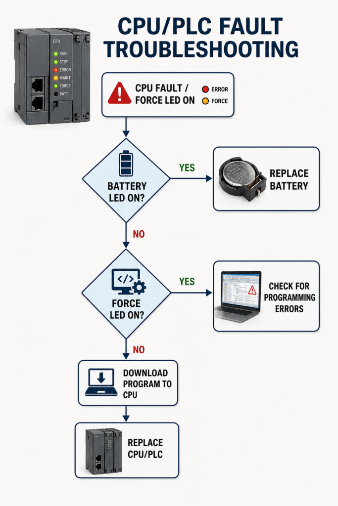
A PLC fault light can make a small problem look expensive.
The CPU may refuse to enter RUN mode, outputs may remain disabled, or the machine may stop halfway through a cycle. It is tempting to restart the controller, download the program again or assume the CPU has failed.
Slow down.
A fault LED does not automatically mean the processor is damaged. The cause could be unstable power, a programming error, an incorrect hardware configuration, a missing I/O module or even an old force left inside the controller.
Make the Machine Safe First
Before resetting the PLC or changing its operating mode, make sure the machine cannot move unexpectedly.
Check for stored pneumatic, hydraulic and mechanical energy. Inform operators and follow the site’s lockout/tagout procedures whenever work exposes someone to hazardous equipment.
A controller returning to RUN mode may immediately restore output commands, depending on the program and electrical design.
Check the CPU Power Supply
Begin with the incoming supply.
Confirm that the CPU is receiving the correct voltage at its actual power terminals. Do not rely only on the power supply’s indicator LED.
Check for:
- Low or unstable 24 V DC
- Loose power terminals
- Blown control fuses
- Overloaded power supply
- Excessive voltage ripple
- Voltage dips when contactors or solenoids energize
A PLC may repeatedly restart or enter a fault state if its supply briefly drops below the permitted level. A standard multimeter may miss a short disturbance, so a recording meter may be needed for intermittent faults.
Read Every Status LED
Do not focus only on the red fault indicator.
Record the condition of all available LEDs, including:
- POWER
- RUN
- STOP
- ERROR or FAULT
- I/O
- COMM
- BATTERY
- FORCE
- BF or bus fault
- SF or system fault
LED meanings vary between manufacturers and controller families. A flashing red light may indicate a recoverable program fault on one PLC and a serious hardware problem on another.
Check the CPU manual for the exact flash pattern.
A battery warning also does not always explain why the PLC stopped. Many modern controllers use nonvolatile memory and may not have a replaceable battery at all. On older CPUs, however, a failed battery can threaten the stored program or retained data when power is removed.
Connect and Read the Fault Code
Go online with the correct programming software and open the controller diagnostics.
Record:
- Exact fault code
- Full fault description
- Time of occurrence
- CPU operating mode
- Affected task or routine
- Module, rack or slot involved
- Events that occurred immediately before the fault
Do this before clearing anything.
Common CPU faults include:
- Watchdog timeout
- Division by zero
- Invalid array reference
- Memory error
- Program corruption
- Missing required I/O
- Firmware mismatch
- Communication-module failure
- Hardware configuration mismatch
The active error may only be the final result. Review the diagnostic history to find the first abnormal event.
Check for Programming Errors
If the CPU faults during a particular machine step, inspect the logic active at that moment.
Possible causes include:
- Dividing by a value that became zero
- Addressing beyond an array limit
- Infinite or excessively long loops
- Invalid motion commands
- Arithmetic overflow
- Incorrect instruction parameters
- Excessive task execution time
Do not simply increase the watchdog time or clear the fault repeatedly. Find out why the program exceeded its expected limits.
Compare the running program with a known working backup, especially if the fault started after a recent logic change.
Check the FORCE Indicator
A force LED normally indicates that one or more forced values exist or that forcing is enabled. It does not necessarily mean that the CPU itself has failed.
Inspect the force table and identify every forced point.
An old forced input or output may cause unexpected machine behaviour or prevent normal sequence operation. After controlled testing:
- Disable forces.
- Remove all installed forces.
- Confirm that no force warning remains.
- Test the real inputs and outputs normally.
Never clear unknown forces blindly while the machine is operating. A forced output may be holding equipment in a particular state.
Confirm the Program Is Loaded
A CPU may refuse to run if:
- No valid user program is present
- The memory card contains an incompatible project
- A download was interrupted
- The project was created for another CPU model
- The firmware revision does not match
- The hardware configuration differs from the real system
Before downloading anything, upload and save the program currently inside the controller if possible.
Downloading an old project can overwrite valid logic, network settings, recipes and calibration values.
Compare:
- CPU model
- Firmware
- Rack layout
- I/O modules
- Communication settings
- Safety configuration
- Project version
Only reload the program when you understand what will be replaced.
Inspect the I/O and Communication Hardware
A CPU fault may actually begin elsewhere.
Check for:
- Missing module
- Incorrect module in a slot
- Loose backplane connection
- Faulted remote I/O
- Duplicate IP address
- PROFINET device-name mismatch
- Failed Ethernet switch
- Communication card error
If the PLC project requires a particular I/O module and that module is unavailable, the controller may remain faulted or refuse to enter RUN mode.
Reset the CPU Only After Recording the Fault
Once the underlying cause has been corrected, clear the fault using the manufacturer’s approved procedure.
Return the controller to RUN mode and test the machine carefully in manual or maintenance mode first.
Confirm that:
- The fault does not return
- Inputs and outputs respond correctly
- Communication remains stable
- No forces remain
- Safety functions operate normally
- Automatic operation completes correctly
Replace the CPU Last
CPU hardware can fail, but replacement should come after power, programming, memory, configuration and connected modules have been checked.
Strong evidence of CPU failure may include:
- Nonrecoverable internal hardware faults
- Repeated memory errors with known-good storage
- Failure with a stable verified supply
- Communication and program-loading failure despite correct setup
- Fault remaining after the CPU is isolated from external modules
Before replacement, back up the program and record critical retained values, firmware revisions and communication settings.
Final Thoughts
A PLC fault light is a starting point, not a diagnosis.
Check power first, record every LED, read the exact fault code and inspect the event history. Confirm that the program, firmware and physical hardware match before resetting or downloading anything.
Most importantly, do not replace the CPU simply because it is displaying the fault. Quite often, the controller is only reporting a problem somewhere else in the system.