A contactor is an electrically controlled switch used to operate higher-power loads such as motors, heaters, pumps and lighting circuits.
Instead of routing the full load current through a small push button or PLC output, the control circuit energizes the contactor coil. The contactor then opens or closes its larger power contacts.
A typical contactor has two main sections:
- Power circuit
- Control circuit
In many electrical schematics, contactors are identified with the letter K, such as K1, although reference designations can vary between standards and companies.
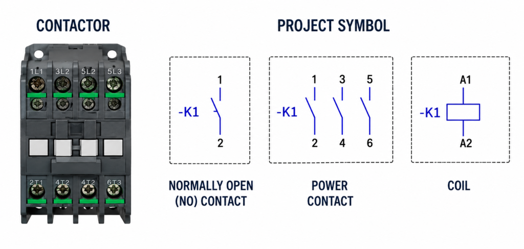
The Power Circuit
The main power contacts carry current to the load.
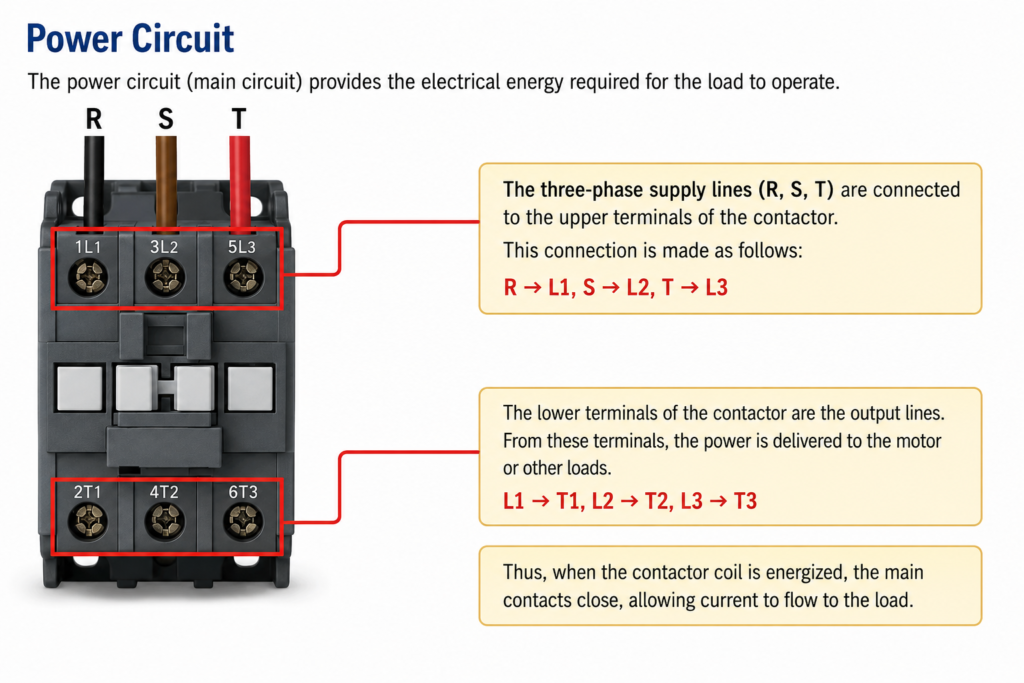
On a three-pole contactor, the incoming terminals are usually marked:
- 1/L1
- 3/L2
- 5/L3
The outgoing terminals are normally:
- 2/T1
- 4/T2
- 6/T3
For a three-phase motor, the supply phases connect to L1, L2 and L3. The motor conductors connect to T1, T2 and T3.
When the contactor is de-energized, the main contacts remain open and the motor receives no power.
When the coil is energized, the contacts close:
- L1 connects to T1
- L2 connects to T2
- L3 connects to T3
Current can then flow to the motor or other connected load.
The main contacts are designed for much higher current than the small contacts used in the control circuit.
The Control Coil
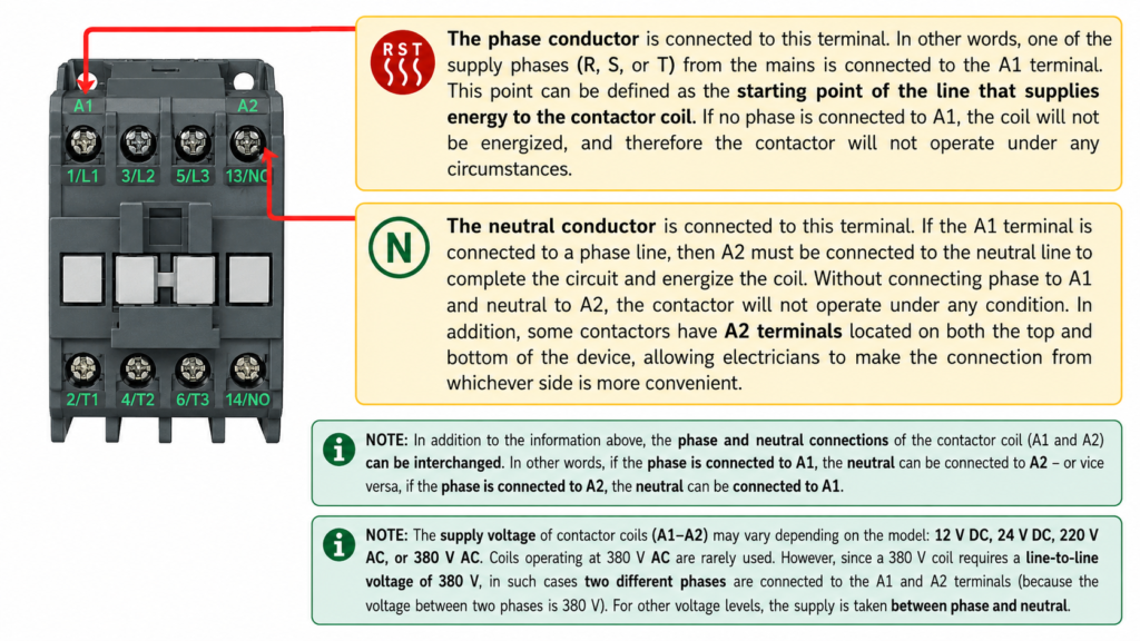
The contactor coil is connected between terminals:
- A1
- A2
When the rated control voltage is applied across A1 and A2, current flows through the coil. This produces a magnetic field that pulls the contactor mechanism inward.
The movement closes the main power contacts and changes the state of the auxiliary contacts.
When coil voltage is removed, an internal spring returns the contactor to its normal position.
The coil voltage must match the control supply. Common coil ratings include:
- 24 V DC
- 24 V AC
- 110 or 120 V AC
- 220 or 230 V AC
- 380 or 400 V AC
Never assume that A1 must always receive phase and A2 must always receive neutral. The correct connection depends on the coil voltage and circuit design. A 230 V AC coil may use phase and neutral, while a 400 V AC coil may be connected between two phases.
Always check the voltage printed on the coil or contactor label.
Normally Open Auxiliary Contact
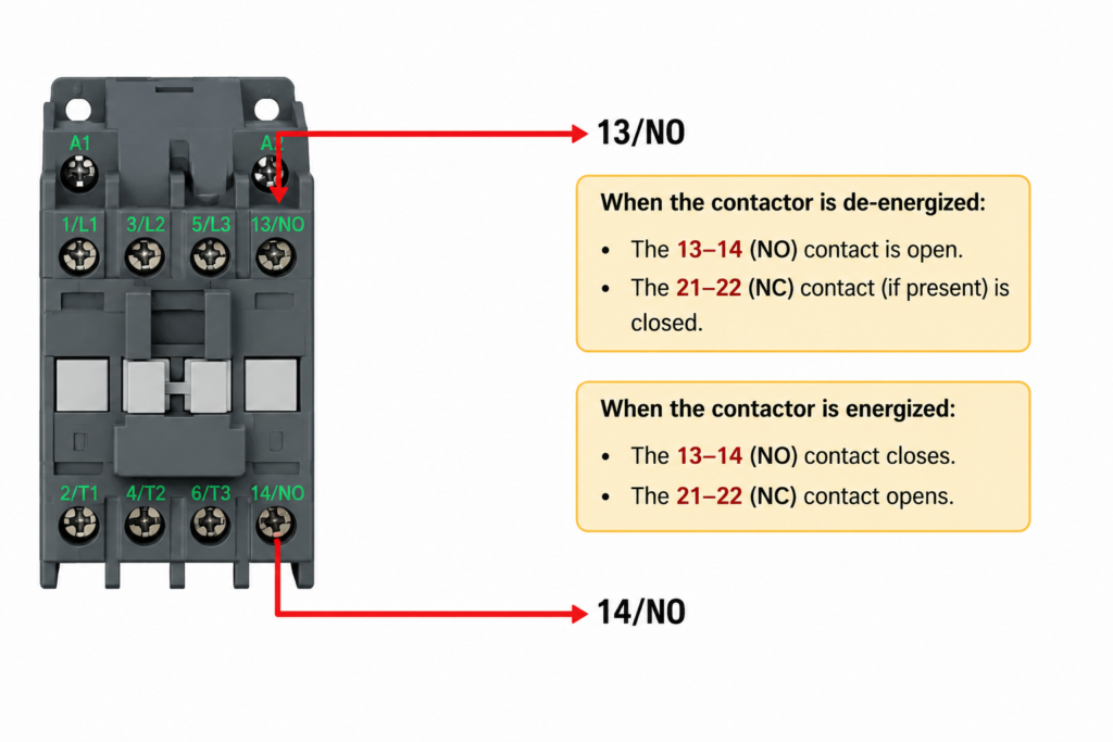
Contactors often include auxiliary contacts for control, feedback, interlocking and signalling.
A common normally open contact is numbered:
13–14
When the contactor is de-energized, terminals 13 and 14 are open.
When the coil is energized, the contact closes.
A 13–14 contact is often used for:
- Contactor holding circuits
- PLC run feedback
- Indicator lamps
- Electrical interlocking
- Sequence control
Normally Closed Auxiliary Contact
A typical normally closed auxiliary contact is numbered:
21–22
When the contactor is de-energized, terminals 21 and 22 are closed.
When the coil is energized, the contact opens.
Normally closed auxiliary contacts are commonly used for electrical interlocking. For example, the NC contact of a reverse contactor can prevent the forward contactor from energizing at the same time.
Contactor Operating Summary
Contactor De-Energized
- No voltage is applied across A1 and A2.
- The magnetic coil is inactive.
- Main contacts L1–T1, L2–T2 and L3–T3 are open.
- The motor or load is disconnected.
- NO contact 13–14 is open.
- NC contact 21–22 is closed.
Contactor Energized
- The rated voltage is applied across A1 and A2.
- The coil creates a magnetic field.
- The contactor pulls in.
- Main power contacts close.
- The connected load receives power.
- NO contact 13–14 closes.
- NC contact 21–22 opens.
Final Thoughts
A contactor allows a low-power control signal to switch a much larger electrical load.
The coil terminals A1 and A2 control the device, the L and T terminals carry the main load current, and auxiliary contacts provide feedback and interlocking.
Understanding these terminal markings makes motor-control diagrams much easier to read and helps prevent wiring mistakes during panel assembly and troubleshooting.