A motor protection circuit breaker, commonly called an MPCB, is designed specifically to protect electric motors.
It combines several protective functions in one compact device:
- Adjustable overload protection
- Short-circuit protection
- Manual motor isolation
- Protection against excessive current
An MPCB is sometimes described as a combination of an MCB and a thermal overload relay. That is a useful comparison, although an MPCB is designed around the operating characteristics of motors, including their higher starting current.
In electrical drawings, it may be identified as Q1, although reference letters vary between projects and standards.
How an MPCB Works
An MPCB normally contains two trip mechanisms.
The thermal trip responds to sustained overload current. If the motor draws slightly more than its rated current for too long, internal bimetallic elements heat up and trip the breaker.
The magnetic trip responds almost immediately to very high short-circuit current.
This combination allows normal motor-starting current to pass while still disconnecting the circuit during a genuine overload or short circuit.
Many three-pole MPCBs are also sensitive to phase-loss conditions because unequal current heats the thermal elements differently. However, the exact protection functions should always be checked in the manufacturer’s documentation.
Input and Output Terminals
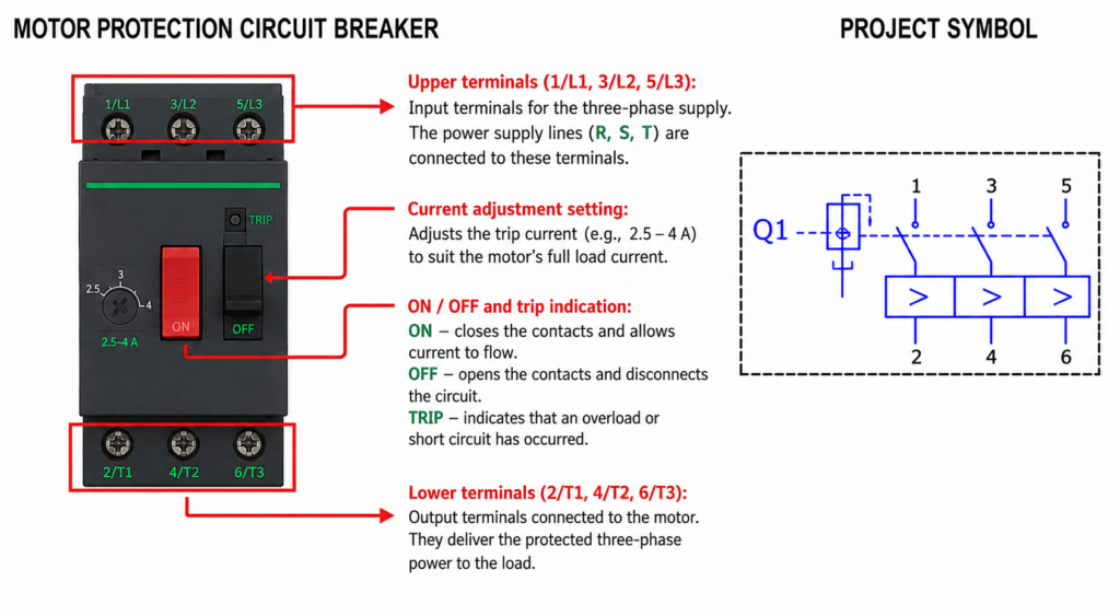
A three-phase MPCB normally has three incoming and three outgoing terminals.
The incoming supply is connected to:
- 1/L1
- 3/L2
- 5/L3
The outgoing conductors are connected to:
- 2/T1
- 4/T2
- 6/T3
The usual current path is therefore:
- L1 → T1
- L2 → T2
- L3 → T3
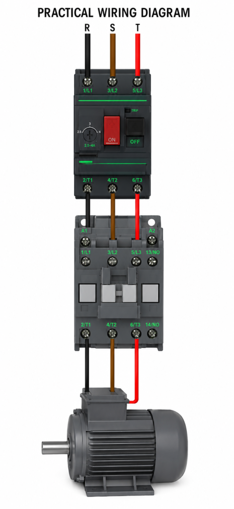
From the MPCB outputs, the conductors may connect to a contactor and then to the motor.
Connecting an MPCB With a Contactor
A common motor starter arrangement is:
Three-phase supply → MPCB → Contactor → Motor
The MPCB provides overload and short-circuit protection. The contactor allows the motor to be started and stopped electrically using push buttons, a PLC or another control device.
The MPCB outputs connect to the contactor inputs:
- MPCB 2/T1 → Contactor 1/L1
- MPCB 4/T2 → Contactor 3/L2
- MPCB 6/T3 → Contactor 5/L3
The contactor outputs then connect to the motor.
An MPCB can manually switch a motor circuit, but it is not normally intended to replace a contactor for frequent automatic operation.
Setting the Motor Current
The adjustment dial should normally be set according to the motor’s rated nameplate current and the equipment manufacturer’s instructions.
For example, if the motor nameplate states 6.2 A, the MPCB should be selected with an adjustment range that includes 6.2 A.
Do not automatically increase the setting when the breaker trips.
Repeated tripping may indicate:
- Mechanical overload
- Missing phase
- Low supply voltage
- Incorrect motor connection
- Worn bearings
- Blocked cooling
- Excessive starting frequency
- Damaged motor windings
A higher setting may stop nuisance trips, but it may also leave the motor inadequately protected.
Manual Operation
Most MPCBs include ON, OFF and sometimes trip or reset controls.
These allow the motor circuit to be:
- Switched on manually
- Disconnected for maintenance
- Reset after an overload trip
- Tested during commissioning
After a trip, the cause should be identified before the device is reset.
MPCB Versus MCB
An ordinary MCB mainly protects circuit conductors from overload and short-circuit current.
An MPCB is designed specifically for motor protection and normally includes an adjustable thermal setting matched to the motor current.
However, the selected MPCB must still have:
- Adequate breaking capacity
- Correct voltage rating
- Suitable adjustment range
- Proper coordination with the contactor
- Compliance with the installation requirements
Final Thoughts
An MPCB provides compact and effective protection for three-phase motors.
Its adjustable thermal trip protects against sustained overload, while its magnetic trip disconnects short circuits quickly. Terminals 1/L1, 3/L2 and 5/L3 receive the supply, while 2/T1, 4/T2 and 6/T3 feed the contactor or motor circuit.
Correct selection and current adjustment are essential. An MPCB set too low may trip unnecessarily, while one set too high may fail to protect the motor properly.