A phase failure relay protects three-phase equipment from supply problems that may damage motors or cause unpredictable operation.
It continuously monitors the incoming phases and allows the motor contactor to energize only when the electrical supply is acceptable. If one phase disappears or the voltage becomes badly unbalanced, the relay changes the state of its output contacts and stops the motor.
Depending on the model, a phase-monitoring relay may detect:
- Phase loss
- Incorrect phase sequence
- Phase-voltage imbalance
- Undervoltage
- Overvoltage
Always check the manufacturer’s specifications because not every relay includes every function.
Why Phase-Loss Protection Matters
A three-phase motor should receive three balanced phase voltages.
If one phase is lost while the motor is running, the motor may continue operating on the remaining phases. This condition is called single phasing.
Motor current rises, torque falls and the windings heat rapidly. Without suitable protection, the motor can eventually burn out.
A phase failure relay helps prevent this by removing power from the contactor coil whenever the monitored supply becomes unacceptable.
Phase Input Terminals
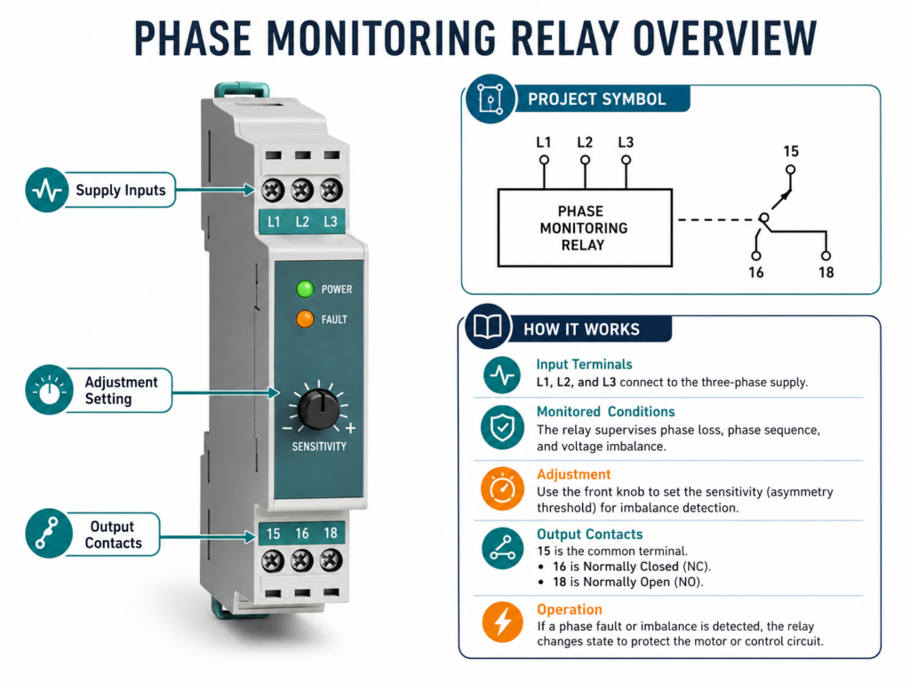
The three incoming phases are normally connected to terminals marked:
- L1
- L2
- L3
Some drawings may use the phase names:
- R
- S
- T
The relay measures these voltages and compares them internally.
When all phases are present, in the correct sequence and within the permitted limits, the relay changes to its healthy state.
If a monitored fault appears, the relay returns to its fault state.
Imbalance Adjustment
Some phase failure relays include an adjustable asymmetry or imbalance setting.
Voltage imbalance means that the phase-to-phase voltages are not equal.
A lower adjustment makes the relay more sensitive, causing it to trip for relatively small differences. A higher setting allows greater variation before the output changes state.
The setting should follow the motor manufacturer’s requirements and the relay documentation. Setting it too sensitively may create nuisance trips, while setting it too high may leave the motor poorly protected.
Output Contact Terminals
A typical phase failure relay includes one changeover contact:
- 15 — Common
- 16 — Normally closed
- 18 — Normally open
When the supply is healthy, the relay normally energizes internally:
- Contact 15–18 closes
- Contact 15–16 opens
When a phase fault occurs:
- Contact 15–18 opens
- Contact 15–16 closes
These contacts can control a motor contactor and an alarm lamp.
Practical Control-Circuit Wiring
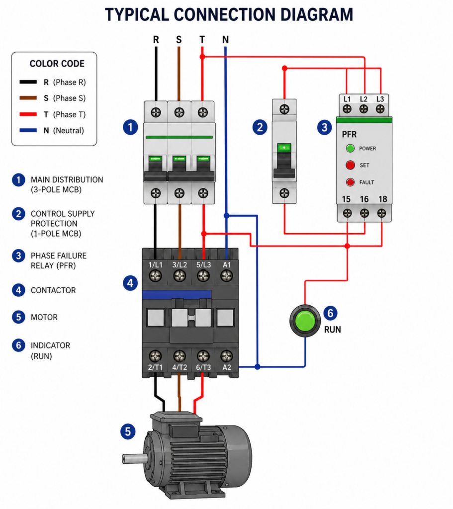
A common arrangement uses one control phase connected through a fuse to terminal 15.
Terminal 18 is then connected to the contactor coil terminal A1. The other coil terminal, A2, connects to the appropriate return conductor, such as neutral for a 230 V AC coil.
When the three-phase supply is healthy:
- The phase relay closes 15–18.
- Control voltage reaches A1.
- The contactor coil energizes.
- Main contacts close.
- The motor receives three-phase power.
If one phase disappears or an unacceptable imbalance develops:
- The relay opens 15–18.
- The contactor coil loses power.
- The main contacts open.
- The motor stops.
Terminal 16 may be connected to a red warning lamp. During normal operation, 15–16 is open and the lamp remains off. When a phase fault occurs, 15–16 closes and the warning lamp turns on.
The exact control-circuit arrangement depends on the relay and coil voltage.
Phase Failure Relay Symbol
There is no single symbol used universally for every phase-monitoring relay.
Electrical drawings often show:
- Three monitored inputs marked L1, L2 and L3
- An internal monitoring block
- A linked changeover output contact
- Terminal numbers 15, 16 and 18
The device reference may be shown as K, KA, F, FR or another project-specific designation.
Final Thoughts
A phase failure relay is a small component that can prevent expensive motor damage.
It monitors the three-phase supply and controls the contactor through terminals 15–16–18. When the supply is healthy, the motor is allowed to run. When phase loss, incorrect sequence or excessive imbalance is detected, the contactor drops out and the motor stops.