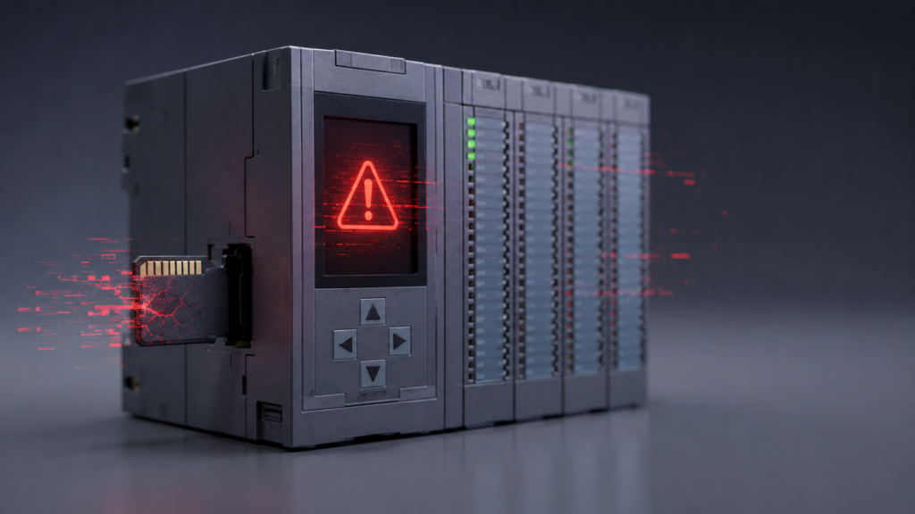
A 24 V DC power supply is supposed to be the calm, boring part of a control panel. It converts the incoming mains voltage, feeds the PLC and quietly gets on with its job.
Until it does not.
An internal power-supply failure can potentially place excessive voltage on the 24 V DC bus, damaging the PLC CPU, I/O modules, communication equipment and other connected electronics. It is uncommon, but the consequences can be expensive because one supply often feeds half the cabinet.
The first priority after such an event is identifying whether the SITOP genuinely produced overvoltage—or whether mains voltage, incorrect maintenance wiring, grounding problems or a surge entered the DC system by another route.
How Much Voltage Can an S7-1500 Accept?
A typical S7-1500 CPU is designed for a nominal 24 V DC supply. For example, Siemens specifies a permissible operating range of 19.2 to 28.8 V DC for the CPU 1513-1 PN. The exact limit must be checked for the CPU and modules actually installed.
Some SITOP product data lists internal-fault overvoltage protection below approximately 33 V. That does not mean every SITOP behaves identically, and it should not be interpreted as a guaranteed safe voltage for every connected PLC component. The complete article number and manual matter.
If a failed supply has pushed the bus significantly beyond its normal range, treat every connected electronic module as suspect—even one that still appears to boot.
First Determine What Actually Happened
Do not immediately replace the power supply and energize the old PLC rack.
Record and inspect:
- Failed SITOP article number and serial number
- PLC and I/O modules connected to it
- Visible damage or smell
- DC-bus voltage before disconnection, when safe
- Incoming AC voltage
- Earthing and 0 V bonding
- Recent electrical work
- Nearby lightning or surge events
- Whether mains voltage could have been connected accidentally to the DC side
Send the failed power supply to Siemens or an authorized service centre where practical. A proper failure analysis can distinguish internal regulation failure from external surge damage or incorrect wiring.
Fuses Do Not Provide Overvoltage Protection
Adding separate fuses or electronic circuit breakers to each PLC branch is good practice, but it does not directly solve sustained overvoltage.
A fuse trips because of excessive current. A PLC exposed to 35 or 40 V may draw enough current to destroy sensitive electronics without producing the fault current needed to clear a fuse quickly.
Likewise, Siemens SITOP selectivity modules are primarily designed to monitor and disconnect load circuits during overload and short-circuit conditions. They improve fault localization and prevent one overloaded branch from collapsing the entire 24 V system, but they should not be assumed to clamp a runaway supply voltage.
Use branch protection—but understand what it protects against.
Add Protection for Transient Surges
A correctly selected 24 V DC surge-protective device can help clamp short-duration transients caused by:
- Lightning-induced surges
- Switching events
- Long external cables
- Inductive loads
- Ground-potential differences
Protection should also be considered on the AC supply feeding the SITOP.
However, an SPD is mainly intended for transient events. It may not safely control a sustained overvoltage caused by a failed regulator unless it is specifically selected and coordinated for that duty.
The SPD’s continuous operating voltage, clamping level, current capability, earthing arrangement and upstream protection all have to match the system.
Use an Independent Overvoltage Disconnect
For a critical PLC supply, consider an independent DC-voltage monitoring device that disconnects the faulty supply when the bus exceeds a chosen threshold.
A possible arrangement is:
AC supply → protective breaker → contactor → SITOP → protected 24 V distribution
The voltage monitor measures the DC output and opens the upstream contactor if the voltage becomes excessive.
There is one catch: semiconductor damage can happen quickly. A conventional monitoring relay and contactor may be too slow for a sharp high-energy event.
For stronger protection, an engineer may specify:
- Fast electronic overvoltage shutdown
- Crowbar protection coordinated with an upstream fuse
- A regulated, isolated DC/DC converter feeding the PLC
- A supply system with independently monitored outputs
These solutions must be engineered properly. A homemade crowbar circuit inside an industrial control panel is not something to improvise during lunch break.
Would Redundant Power Supplies Help?
Two power supplies combined through a redundancy or ORing module improve availability when one supply loses output.
Siemens describes its redundancy modules as devices for decoupling two power supplies.
That does not automatically mean the module will protect the load when one supply fails high when one supply fails high.
A high-output-voltage failure is different from an ordinary loss of supply. Confirm explicitly that the selected redundancy system detects and isolates overvoltage; otherwise, the defective supply may still raise the common DC bus.
Redundancy is useful, but it is not a substitute for verified overvoltage protection.
Separate the PLC Supply From Noisy Loads
Do not place the CPU, relay coils, large valve banks and contactors on one unsegmented 24 V branch if downtime or equipment damage would be serious.
A better arrangement may use separate protected branches for:
- PLC CPU and communication modules
- Digital I/O
- Analog and instrumentation circuits
- Contactors and solenoids
- External field devices
For especially important controllers, a dedicated regulated supply or isolated DC/DC converter can prevent disturbances on the field-device bus from reaching the CPU.
Inspect Grounding and Wiring
Overvoltage-like damage does not always originate inside the power supply.
Check for:
- 0 V incorrectly connected to mains conductors
- Poor protective-earth bonding
- Long outdoor cables without surge protection
- Shield connections carrying fault current
- Mains and 24 V terminals positioned too closely
- Incorrect replacement wiring
- Inductive loads without suppression
Good equipotential bonding helps surge-protective devices work correctly and reduces destructive voltage differences between interconnected equipment.
What to Do After an Incident
After a suspected overvoltage event:
- Isolate the damaged system.
- Do not reuse the failed power supply.
- Inspect and test every connected branch separately.
- Replace visibly damaged modules.
- Restore the PLC using a known-good supply.
- Verify inputs, outputs and communication thoroughly.
- Monitor the new 24 V supply during normal machine operation.
- Send failed equipment for professional analysis.
- Redesign the distribution before returning the machine to long-term service.
Modules that survived the first event may contain weakened protection components and fail later. For critical machinery, replacement can be safer than trusting apparently functional electronics.
Final Thoughts
A SITOP power supply can theoretically fail in a way that damages equipment on its output bus, although the exact root cause should be proven rather than assumed.
The best protection is layered:
- A quality power supply with documented internal protection
- AC and DC surge protection
- Proper grounding
- Separate protected 24 V branches
- Independent overvoltage monitoring where justified
- Correctly engineered redundancy or isolation
- Supply-health monitoring and alarms
Fuses and selectivity modules remain important, but they mainly protect against overcurrent. They cannot be treated as complete protection against a failed supply producing excessive voltage.