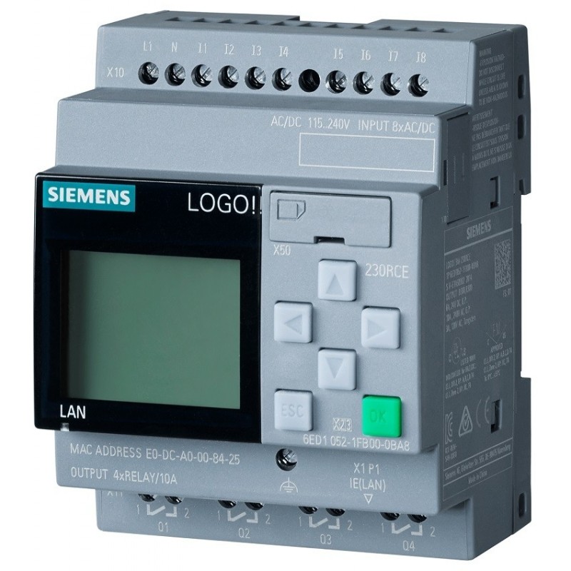
A Siemens LOGO! can regulate pump speed from a PT1000 temperature sensor and send a 0–10 V command to a frequency inverter. The most important decision is whether you want a simple temperature-to-speed relationship or genuine closed-loop temperature control.
For maintaining approximately 2°C, the LOGO! PI Controller is normally the better option.
Understand the Measurement Limit
The LOGO! AM2 RTD supports PT100 and PT1000 sensors over a measuring range of approximately −50°C to +200°C. Its specified resolution is 0.25°C, but the module’s measurement error is considerably larger than one count. Therefore, it can regulate around 2°C, but it cannot guarantee that the real temperature is exactly 2.00°C.
Resolution and accuracy are not the same thing:
- Resolution determines the smallest displayed change.
- Accuracy determines how close the reading is to the real temperature.
- Sensor tolerance, wiring resistance and installation also influence the result.
Use a three-wire PT1000 connection where possible. Keep the sensor cable separated from motor and VFD cables, and follow Siemens’ shielding recommendations for analog wiring.
Scaling the PT1000 Input
For the older LOGO! system, analog values are normally processed internally as numbers between 0 and 1000.
With the AM2 RTD configured for a detailed temperature display, use an Analog Amplifier with:
- Gain: 2.50
- Offset: −500
- Decimal places: 1
This produces a value expressed in tenths of a degree:
- −50.0°C = −500
- 0.0°C = 0
- 1.0°C = 10
- 2.0°C = 20
- 4.0°C = 40
- 200.0°C = 2000
Therefore, the PI controller setpoint for 2°C should be entered as:
SP = 20
This scaling method follows the gain-and-offset system used by LOGO! for analog values.
Scaling the 0–10 V Output
The LOGO! AM2 AQ represents its 0–10 V voltage output with an internal value of 0–1000.
That means:
| Pump command | LOGO! AQ value | Output voltage |
|---|---|---|
| 0% | 0 | 0 V |
| 5% | 50 | 0.5 V |
| 10% | 100 | 1 V |
| 40% | 400 | 4 V |
| 100% | 1000 | 10 V |
The VFD must also be configured so that 0–10 V corresponds to the required frequency range. Its minimum frequency, maximum frequency, acceleration time and deceleration time should be configured inside the drive.
Option 1: Simple Proportional Mapping
Your requested relationship is:
- 1°C → 10% speed
- 4°C → 100% speed
- Minimum while running → 5%
A straight line between 1°C and 4°C gives:
Pump speed increases by 30% for every 1°C increase.
With temperature represented in tenths of a degree, the LOGO! calculation is:
AQ = 30 × Temperature − 200
Examples:
- At 1°C: 30 × 10 − 200 = 100, or 10%
- At 2°C: 30 × 20 − 200 = 400, or 40%
- At 4°C: 30 × 40 − 200 = 1000, or 100%
Use Max/Min blocks to limit the calculated result:
- Minimum while running: 50
- Maximum: 1000
Then use an Analog Multiplexer controlled by the pump-running signal:
- Pump stopped → AQ = 0
- Pump running → AQ = calculated value, limited to 50–1000
The approximate LOGO! block sequence would be:
AM2 RTD input → Analog Amplifier → Arithmetic Instruction → Max/Min limitation → Analog Multiplexer → AM2 AQ
This method is simple, but it is not true temperature regulation. It merely assigns a predefined speed to each measured temperature. At 2°C, the specified points produce 40% speed. A different “normal speed” at 2°C would require a two-part characteristic rather than one straight line.
Option 2: Use the LOGO! PI Controller
For actual regulation, connect the scaled temperature to the PI Controller’s PV input.
Suggested basic configuration:
- PV: Scaled PT1000 temperature
- SP: 20, representing 2.0°C
- A/M: Automatic when the pump is permitted to run
- Mq: Initial pump command, such as 50 or the normal operating speed
- Output AQ: Speed command sent toward the AM2 AQ
- Output range: 0–1000
According to Siemens’ PI-controller behaviour, the downwards direction should be selected when the output must increase as the process value rises above the setpoint. That matches an application where increasing pump speed reduces the temperature.
Therefore:
- Temperature above 2°C → pump speed increases
- Temperature below 2°C → pump speed decreases
- Temperature at 2°C → controller holds or slowly corrects its output
Confirm the direction during commissioning. If increasing pump speed actually raises the measured temperature, the controller direction must be reversed.
Applying the 5% Minimum
The PI block output can range from 0 to 1000. Place a Max block after the controller so that the command cannot fall below 50 while the pump is running.
A practical sequence is:
- Keep the PI controller in manual mode while the heat pump is off.
- Set manual value Mq to 50 or a suitable starting speed.
- Use a separate Analog Multiplexer to force the physical AQ output to zero while stopped.
- When the run signal appears, change the PI controller to automatic.
- Allow the output to begin from the manual value rather than jumping abruptly.
Siemens’ PI implementation adopts the manual value when changing into automatic mode, which can help provide a smoother startup.
PI Tuning
Temperature systems usually react slowly. Excessive controller gain can cause the pump speed and temperature to oscillate.
A sensible commissioning method is:
- Begin with proportional control only.
- Use a low controller gain.
- Observe how temperature responds to speed changes.
- Add integral action gradually.
- Use a relatively long integral time.
- Test after the complete system reaches stable operating conditions.
In LOGO!, setting the integral time to 99:59 disables the integral component, allowing proportional-only testing.
An Analog Filter before the PI block can also reduce unnecessary speed changes caused by small measurement fluctuations. Avoid excessive filtering because it delays the controller’s response.
Would a Temperature Transmitter Be Better?
A narrow-range transmitter can improve usable resolution.
For example, a transmitter configured for:
−10°C to +15°C = 0–10 V
spreads only 25°C across the LOGO!’s 1000 input steps. The theoretical resolution becomes approximately 0.025°C per step.
To represent this range in tenths of a degree, use:
- Gain: 0.25
- Offset: −100
- Decimal places: 1
However, this does not automatically guarantee 0.025°C accuracy. The transmitter accuracy, PT1000 tolerance, analog-input accuracy and electrical noise still matter.
For genuinely tight temperature control, a quality transmitter with a narrow configured range—or a digital transmitter using Modbus—may be more suitable than connecting the PT1000 directly to the older AM2 RTD.
LOGO! 9 Considerations
LOGO! Soft Comfort V9 is programming software. Installing it does not increase the analog resolution of older LOGO! hardware.
The newer LOGO! 9 platform offers the AM4 AI/AQ with selectable analog resolutions of 1000, 4095 or 10,000 steps and supports floating-point processing. However, LOGO! 9 hardware is not compatible with previous LOGO! expansion modules, so an older AM2 RTD or AM2 AQ cannot simply be transferred to a LOGO! 9 base module.
Recommended Solution
For moderate temperature accuracy:
- Keep the AM2 RTD.
- Use a three-wire PT1000.
- Scale the temperature into tenths of a degree.
- Use the LOGO! PI Controller with SP = 20.
- Select the controller direction so that temperature above 2°C increases pump speed.
- Limit the active output to 50–1000.
- Force AQ to zero when the heat pump is not running.
- Configure acceleration and minimum frequency in the VFD.
For tighter control, use a calibrated narrow-range temperature transmitter or a higher-resolution digital measurement system.
The simple proportional formula is suitable when you only need a predictable speed curve. The PI controller is the better choice when the actual objective is to keep the temperature close to 2°C despite changing loads and operating conditions.