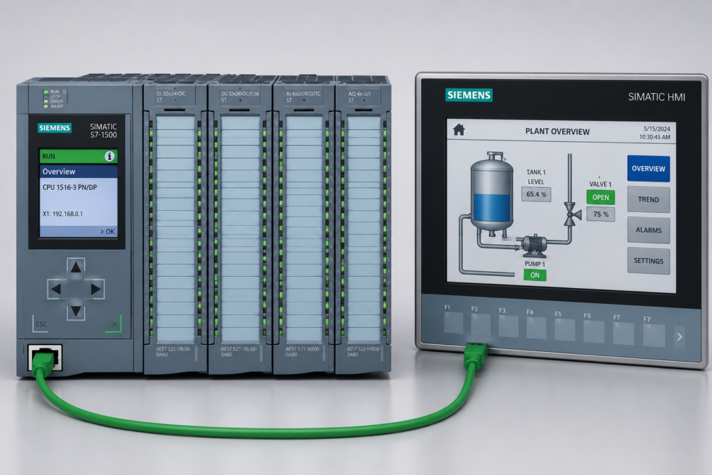
An HMI is one of the most useful tools available during machine commissioning. It shows sensor states, motor commands, alarms, analog measurements and operating conditions in a convenient visual format.
But an HMI is not a live window into every PLC scan.
The information on the screen may already be several PLC cycles old. A displayed tag can appear healthy even though the controller has processed a completely different state.
Treating the HMI as a perfect representation of real-time PLC execution can lead technicians in the wrong direction.
The HMI and PLC Run at Different Speeds
A PLC may execute its main program every few milliseconds.
The HMI usually updates much more slowly. Depending on its configuration, communication network and number of tags, it might request new data every:
- 100 milliseconds
- 250 milliseconds
- 500 milliseconds
- One second
- Several seconds
During a single HMI update period, the PLC may complete dozens or even hundreds of program scans.
A condition could turn on, affect the logic and turn off again before the HMI performs its next poll. The operator never sees it, but the PLC still responded to it.
HMI Data Is Polled Asynchronously
The HMI does not normally read every PLC tag at a fixed point in the CPU scan.
Instead, it communicates independently while the PLC continues executing its program.
A simplified sequence may look like this:
- A field input changes.
- The remote input module reports the new state.
- The PLC processes the change.
- The PLC logic resets or modifies another tag.
- The HMI requests its next update.
- The operator sees only the later state.
The HMI may therefore display the result of an event without showing the short condition that caused it.
It can also read different tags at slightly different moments. This may produce a screen containing a mixture of values that never existed together during one PLC scan.
A “Ready” Indication May Already Be Outdated
Imagine a motor with the following permissives:
- Emergency stop healthy
- Overload relay healthy
- Drive communication healthy
- Guard door closed
- Process pressure available
The HMI displays Motor Ready.
A moment later, the drive communication bit drops. The PLC immediately removes the motor-ready condition and stops the motor.
Before the HMI refreshes, the operator may still see:
- Motor Ready: green
- Start command: active
- Motor running: false
This can make the output appear faulty even though the PLC correctly removed the permissive several scans earlier.
By the time the screen updates, the original event may already have recovered.
Stable Trends Can Hide Fast Oscillation
HMI trends are useful for observing slow process behaviour, but their sampling rate may hide rapid changes.
Suppose a pressure-related logic bit alternates between true and false every 40 milliseconds. An HMI trend sampling once per second may capture only one value from each second.
The resulting trend could appear completely stable.
Meanwhile, the PLC may be:
- Repeatedly setting and resetting an output
- Restarting a timer
- Changing sequence states
- Chattering a command bit
- Generating brief alarms
For fast or intermittent problems, use a PLC trace rather than relying solely on an HMI trend.
A trace can record signals at the task or scan rate, revealing changes the HMI cannot display.
Analog Values Can Remain Believable When Stale
A frozen digital signal is often easy to notice. A stale analog value is more dangerous because it can continue looking realistic.
For example, a pressure transmitter may last report 4.6 bar before communication is lost. If the receiving logic retains the last value, the HMI may continue displaying 4.6 bar.
Nothing on the screen appears obviously wrong.
However, the displayed number may no longer represent the process.
Important analog values should be accompanied by information such as:
- Communication status
- Data-valid indication
- Signal-quality status
- Device fault bit
- Update counter
- Timestamp of the latest valid value
- Stale-data alarm
A numerical value without a validity check should not automatically be trusted.
Remote I/O Creates Another Timing Layer
When sensors and outputs are located on remote I/O, the update path becomes longer.
An input change may pass through:
- The field sensor
- Input-module filtering
- Remote I/O processing
- Industrial Ethernet communication
- PLC input processing
- Program execution
- HMI communication
- Screen rendering
Each stage adds delay.
The HMI might show the remote input as active while the PLC program has already processed its falling edge. Alternatively, the PLC may command a remote output off while the physical output remains active briefly because the updated command has not yet reached the remote module.
This does not necessarily indicate a defective PLC or HMI. It may simply be normal communication and module response time.
One-Scan Events Are Nearly Invisible
Many PLC programs use one-shot or edge-detection instructions.
These signals may exist for only one scan. If the CPU scan time is 5 milliseconds, the tag could be active for just 5 milliseconds.
An HMI polling every 500 milliseconds has very little chance of capturing it.
Important one-scan events should be copied into a latched diagnostic bit or event buffer.
For example:
- Original one-shot starts a machine sequence.
- A separate diagnostic bit is set at the same time.
- The diagnostic bit remains active until acknowledged.
- A counter records how many times the event occurred.
- A timestamp records when it happened.
This provides evidence after the original signal has disappeared.
HMI Screens May Apply Additional Processing
The displayed value is not always a direct copy of the PLC tag.
The HMI project may apply:
- Scaling
- Decimal formatting
- Animation conditions
- Visibility logic
- Colour changes
- Deadbands
- Alarm delays
- Trend compression
- Smoothing
- Script calculations
For example, a raw analog input may oscillate slightly while the HMI rounds it to one decimal place. The operator sees a stable 2.0°C even though the PLC value is moving between 1.96°C and 2.04°C.
Similarly, a status lamp may remain green because its animation references a different tag than the actual PLC permissive.
Always verify which PLC address or symbolic tag the HMI object is using.
Common Misleading Observations
“The HMI Says the Motor Is Ready”
The displayed ready condition may be delayed. Check the actual permissive bits, interlocks and diagnostic history inside the PLC.
“The Input Never Changed”
It may have changed for only one scan. Use a trace, event latch or counter.
“The Analog Value Is Stable”
The data may be stale, heavily filtered or rounded on the HMI.
“The Output Is Off, but the Device Is Still Running”
The command may still be travelling to remote I/O, or the physical actuator may have its own release delay.
“The Alarm Appeared for No Reason”
The condition may have occurred and disappeared between HMI updates. The alarm system may have captured an event that the normal screen never displayed.
How to Verify the Real PLC State
When troubleshooting timing-related faults, examine the PLC directly.
Use:
- Online watch tables
- Cross-reference tools
- PLC trace functions
- Diagnostic buffers
- Task-cycle measurements
- Remote I/O diagnostics
- Sequence-state history
- Event counters
- Timestamps
- Latched fault bits
Monitor the raw input, processed input, permissive, command and physical output feedback together.
For example, when troubleshooting a motor, record:
- Raw start request
- All permissives
- Motor-ready result
- PLC output command
- Drive control word
- Drive running feedback
- Fault and communication status
This makes it possible to see which condition changed first.
Improve the HMI for Troubleshooting
A good HMI should display more than the final command.
Useful diagnostic screens can include:
- Individual permissive states
- First-out fault information
- Communication-quality indicators
- Last update time
- Raw and scaled analog values
- Current sequence step
- Previous sequence step
- Reason an output is inhibited
- Counter showing how often a fault occurred
A message such as Motor Not Ready is not very helpful.
A better diagnostic display might show:
Motor start blocked: Drive communication lost at 14:32:18
The second message tells the technician what happened and when.
Final Thoughts
The HMI shows a sampled and processed view of the PLC system. It does not reproduce every scan exactly as it happened.
Tags may be delayed, buffered, rounded or updated at different moments. Short events may disappear before the screen refreshes, while stale analog values can remain visible long after communication has failed.
During serious troubleshooting, never rely on the HMI alone.
Verify the raw PLC tags, communication status, task timing and actual sequence of events. The screen tells you what it managed to observe. The PLC trace tells you what really happened.