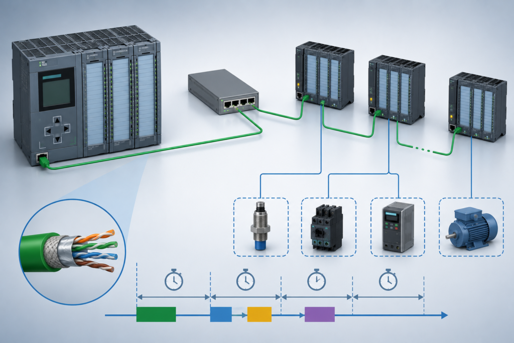
Modern automation systems rarely keep every input and output beside the PLC. Sensors, valves, drives and I/O modules are often distributed throughout the machine and connected through industrial Ethernet.
Common systems include:
- PROFINET
- EtherNet/IP
- Modbus TCP
- Remote I/O stations
- Managed industrial switches
- Distributed drives and field devices
This arrangement reduces wiring and makes large machines easier to expand. However, it also introduces communication delay.
A sensor may change state instantly in the field, but the PLC does not necessarily receive that new state at the same moment.
The delay may only be a few milliseconds. In a slow process, that is usually harmless. In high-speed sequencing, positioning or tightly timed machine control, those milliseconds can determine whether the sequence succeeds or fails.
The Remote I/O Signal Path
With local I/O, the signal path is relatively short:
Sensor → Input module → PLC program
With remote I/O, several additional stages are involved:
- The sensor changes state.
- The remote input module detects the change.
- Input filtering may delay recognition.
- The remote station prepares updated network data.
- The Ethernet frame travels through the network.
- The PLC communication system receives the data.
- The PLC program processes the new input.
- The output command is calculated.
- The command travels back to a remote output module.
- The actuator responds physically.
Each stage adds a small amount of delay.
The total response time is therefore much more than the PLC scan time alone.
Input-Module Filtering
Digital input modules often include configurable filtering to prevent electrical noise or contact bounce from creating false signals.
For example, an input may be required to remain continuously active for several milliseconds before the module reports it as true.
This is useful for ordinary switches and noisy field wiring, but it can also hide short pulses.
Suppose a sensor pulse lasts 3 milliseconds while the input filter is configured for 5 milliseconds. The PLC may never receive the event, even when the network and program are functioning correctly.
When high-speed events matter, check the input filter before blaming the Ethernet network.
Network Update Time
Industrial Ethernet devices normally exchange cyclic data at configured intervals.
The exact terminology depends on the protocol:
- PROFINET uses configured update times.
- EtherNet/IP commonly uses a Requested Packet Interval.
- Modbus TCP usually depends on how frequently the PLC polls each device.
A faster update interval reduces communication delay, but it also increases network and device processing load.
Configuring every device for the fastest possible update is not always good engineering. The update time should match the real process requirement.
A temperature transmitter does not need the same communication speed as a registration sensor on a high-speed packaging machine.
PLC Scan Time Still Matters
Receiving the network update does not automatically mean the user program has already processed it.
The new data must become available to the relevant PLC task. The program then has to reach the logic that uses the input.
A simplified timing sequence may be:
- Sensor changes
- Remote module detects the signal
- Network transmits the update
- PLC receives the data
- Main cyclic task begins
- Logic evaluates the input
- Output command is calculated
- Remote output receives the command
If the PLC task has a long or variable cycle time, the signal can wait longer before being used.
For high-speed operations, a timed cyclic task, hardware interrupt or dedicated technology module may provide more predictable behaviour than ordinary cyclic logic.
Ethernet Delay Is Not Always Constant
Communication time may vary slightly from one update to another. This variation is known as jitter.
Possible causes include:
- Other traffic on the network
- Switch buffering
- Device processing load
- Network retries
- Diagnostic traffic
- HMI communication
- Programming-device access
- Incorrect topology
- Duplex or speed mismatch
- Faulty cables or connectors
A sequence may work correctly for hundreds of cycles and then fail once because one update arrived slightly later than normal.
This is why timing faults often feel random, even when the underlying problem is repeatable under the right conditions.
Asynchronous Input Updates
Not every device updates at the same time.
One remote station may provide data every 2 milliseconds, another every 8 milliseconds and a Modbus TCP device every 200 milliseconds.
The PLC can therefore process a mixture of values captured at different moments.
Consider a sequence that uses two sensors:
- Sensor A is connected to local I/O.
- Sensor B is connected to a remote station.
Both sensors may change physically at almost the same time. However, Sensor A can reach the CPU earlier than Sensor B.
The PLC may briefly see:
- Sensor A = true
- Sensor B = false
On the next scan, both may be true.
If the logic assumes the two signals always change together, the temporary mismatch can trigger an alarm or an incorrect sequence transition.
Common Symptoms of Remote I/O Timing Problems
Intermittent Startup Faults
A machine may expect several permissives to become healthy during startup.
If one remote condition arrives later than the others, the program may evaluate the sequence too early and generate a startup fault.
Adding an appropriate validation delay or requiring all permissives to remain healthy for a defined period can prevent this.
Sequence Mismatch
A sequence step may advance based on one sensor before another remote signal has updated.
The following step then sees an impossible combination and stops the machine.
Missed Sensor Transitions
Short pulses can be lost because of:
- Input filtering
- Slow network update time
- Long PLC scan time
- Pulse duration shorter than the complete system response
A high-speed counter or input-latching function may be required.
Random Machine Stops
Brief network interruptions can cause an I/O station to become unavailable or its data to be marked invalid.
The PLC may react by stopping equipment, even though communication recovers almost immediately.
Inconsistent Fault Reproduction
The fault may appear only when communication, scan time and physical machine timing align in an unfortunate way.
Step-by-step testing may never reproduce it because the machine is moving too slowly.
Protocol-Specific Considerations
PROFINET
PROFINET is designed for cyclic industrial communication and can provide fast, predictable updates when configured correctly.
Check:
- Configured update time
- Reduction ratio or send clock, where applicable
- Network topology
- Device diagnostics
- Watchdog time
- Switch compatibility
- Real-time communication settings
Very short update times should only be used when the devices and network design support them.
EtherNet/IP
EtherNet/IP cyclic I/O commonly uses an RPI value.
A short RPI provides frequent updates, but several devices with aggressive settings can consume significant network and controller resources.
Also verify:
- Connection timeouts
- Multicast or unicast configuration
- Managed-switch IGMP settings
- Connection count
- Device update capabilities
Incorrect multicast management can create unnecessary network traffic.
Modbus TCP
Modbus TCP is often based on request-and-response polling rather than deterministic cyclic I/O.
The PLC or communication master asks each device for data, waits for the response and then moves to the next request.
The total update time depends on:
- Number of devices
- Number of registers
- Polling sequence
- Device response time
- Timeout settings
- Failed communication retries
Modbus TCP may be perfectly suitable for energy meters, temperature controllers and slow process data. It is usually less appropriate for events requiring precise millisecond-level timing.
Managed Switches and Network Design
An industrial managed switch does not automatically make the network faster. Its value comes from diagnostics, traffic control and predictable network behaviour.
Useful switch features may include:
- Port statistics
- Error counters
- Network topology information
- Quality-of-service settings
- Redundancy support
- IGMP snooping
- Port mirroring
- Alarm contacts
During troubleshooting, inspect ports for:
- Packet errors
- Dropped frames
- Link interruptions
- Excessive broadcast traffic
- Speed negotiation problems
- Repeated device reconnections
A cable may appear operational while still producing intermittent errors under vibration or electrical noise.
Designing Logic for Communication Delay
Good PLC logic should not assume that every field signal updates simultaneously.
Useful methods include:
Input Validation
Require a condition to remain stable for a defined time before using it.
This prevents a brief timing mismatch from advancing or stopping a sequence.
Handshake Signals
Where two controllers or devices coordinate an action, use request, acknowledge and complete signals instead of depending on exact timing.
State Machines
A structured sequence should wait for clearly defined conditions before moving to the next step.
Avoid relying on several independent bits changing in a particular order without confirmation.
Timeouts
Every network-dependent action should have a reasonable timeout.
A timeout should generate a meaningful fault showing which response was not received.
Data-Quality Monitoring
Monitor:
- Device connected status
- I/O validity
- Communication fault bits
- Update counters
- Watchdog signals
- Timestamps
Do not continue trusting the last process value indefinitely after communication stops.
Event Latching
If a short event must not be missed, latch it in the remote device, input module or PLC until the program acknowledges it.
Troubleshooting Remote I/O Timing
When a fault appears random, record the entire signal chain.
Monitor:
- Raw field input
- Remote I/O status
- PLC process-image input
- Processed program condition
- Sequence step
- Output command
- Remote output state
- Device feedback
- Network diagnostics
Use a PLC trace whenever possible. An HMI trend may update too slowly to show the real sequence.
Also compare:
- Minimum, current and maximum PLC scan time
- Network update intervals
- Input-filter settings
- Device response times
- HMI polling rates
The goal is to determine where the delay occurs—not simply to prove that a signal eventually changed.
Final Thoughts
Remote I/O and industrial Ethernet make modern automation systems flexible and scalable, but they also separate physical events from PLC execution in time.
A sensor changes first. The input module detects it later. The network delivers the update after that. The PLC processes it during a suitable scan, and the resulting output command must travel back through the system.
Most of these delays are tiny. Together, however, they can create intermittent startup faults, missed transitions, race conditions and sequence mismatches.
Reliable control logic must account for communication latency, asynchronous updates and timing jitter. When a remote I/O problem appears random, the real question is often not whether the signal changed—but exactly when each part of the system received it.