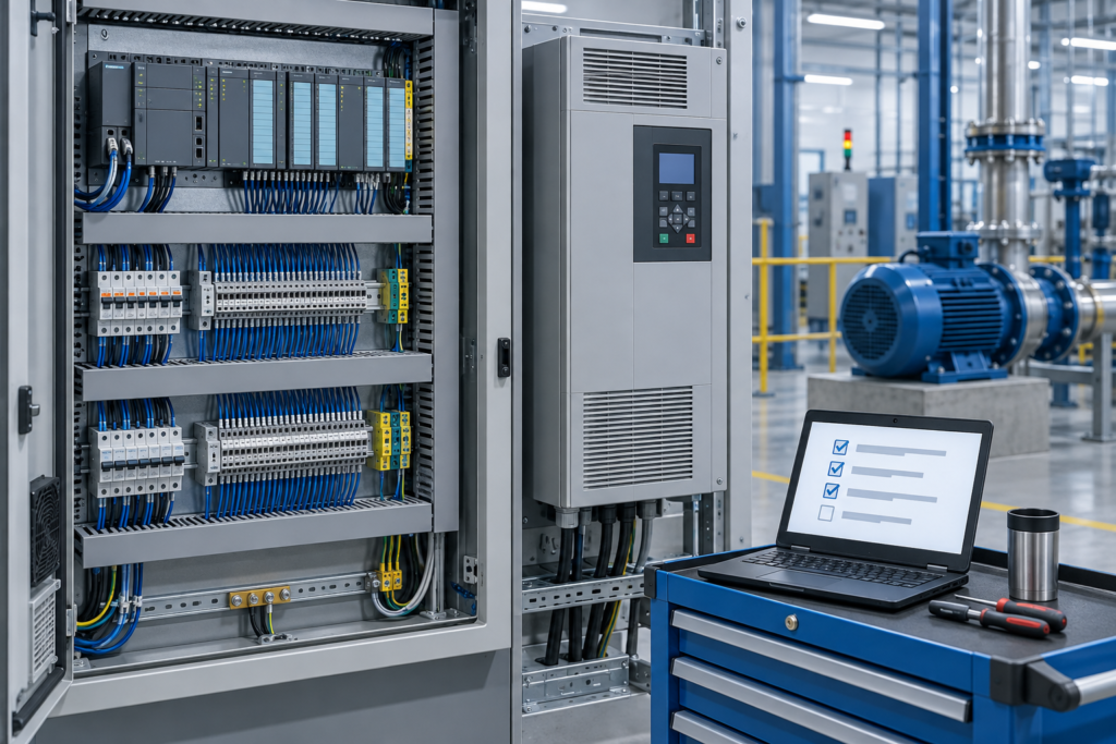
By Dovydas Kersys · Chapter 28 of 58 in Machine Commissioning.
Before you begin: Follow the machine documentation, risk assessment, site procedures and lockout/tagout requirements. Commissioning can expose personnel to electrical energy, stored pressure and unexpected motion. Never defeat a safety function merely to make a test easier. Examples and diagrams are generic and must be checked against the actual machine.
An emergency stop function must be tested as a complete safety chain: initiating device, safety logic, final switching elements, hazard removal, reset and restart prevention.

Proof-test the whole safety function from button to hazard.
Why this matters during commissioning
Testing only the red button lamp or safety input LED does not prove that hazardous motion actually stops.
Commissioning procedure
- Identify every emergency stop device and the hazards it is intended to control.
- Activate each device individually during a controlled test.
- Verify safety logic detects both channels where applicable.
- Confirm final switching elements de-energize and hazardous motion/energy reaches the intended safe state.
- Verify diagnostics, reset behavior and restart prevention.
- Test device release without reset to confirm the machine does not restart.
Common failure patterns
- One channel wired but second channel not monitored.
- Reset bypassed by PLC logic.
- Some actuator remains energized because it is outside the safety chain.
- Fault reset also acts as start command.
Evidence to record
- Device tested
- Safety input status
- Final element status
- Stopping result
- Reset/restart result
- Pass/fail
FIELD RULE: A safety input LED is not a proof test.
Continue the series
- Previous chapter: Braking and Controlled Stops: Commissioning Guide
- Next chapter: Guards and Interlocks: Commissioning Guide
- Browse all Machine Commissioning chapters
Adapted from Machine Commissioning for Maintenance and Automation Technicians, by Dovydas Kersys. © 2026 Dovydas Kersys. Featured cover image is an AI-generated editorial illustration.