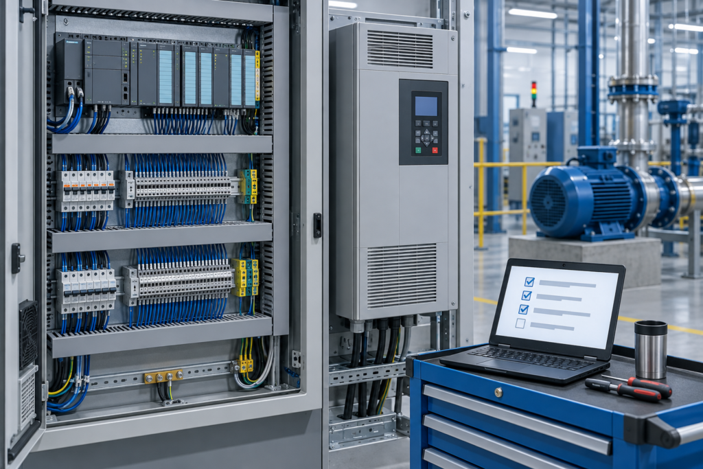
By Dovydas Kersys · Chapter 40 of 58 in Machine Commissioning.
Before you begin: Follow the machine documentation, risk assessment, site procedures and lockout/tagout requirements. Commissioning can expose personnel to electrical energy, stored pressure and unexpected motion. Never defeat a safety function merely to make a test easier. Examples and diagrams are generic and must be checked against the actual machine.
Temperature and pressure loops influence alarms, interlocks, PID control and safety decisions. Verify sensor type, range, installation, scaling and realistic process response.
Why this matters during commissioning
A transmitter can be electrically correct while mechanically installed in a poor location or isolated by a closed valve.
Commissioning procedure
- Confirm sensor/transmitter model and configured range.
- Verify process connection, impulse lines, thermowell or mounting condition.
- Apply a known reference or compare with calibrated instrument where required.
- Check PLC scaling and HMI units.
- Test alarms/interlocks at appropriate simulated or process values.
- Observe response time for plausibility.
Common failure patterns
- Pressure transmitter isolation valve left closed.
- RTD wiring mode configured incorrectly.
- Temperature unit mismatch C/F.
- Sensor lag causes control tuning that is too aggressive.
Evidence to record
- Measured value and test point
- Expected value / expected state
- Observed value / observed state
- Pass/fail result and any deviation
- Name/date or responsible person where required
FIELD RULE: Instrumentation commissioning has two halves: the electrical signal and the physical measurement point.
Continue the series
- Previous chapter: Hydraulic Commissioning
- Next chapter: Control Valve Commissioning
- Browse all Machine Commissioning chapters
Adapted from Machine Commissioning for Maintenance and Automation Technicians, by Dovydas Kersys. © 2026 Dovydas Kersys. Featured cover image is an AI-generated editorial illustration.