By Dovydas Kersys · Chapter 8 of 40 in Hydraulic Troubleshooting.
Before you begin: Hydraulic equipment can contain lethal stored energy. Only trained and authorized personnel should perform hydraulic work. Isolate energy, support loads, verify the pressure state, use pressure-rated instruments and follow site-specific lockout/tagout procedures. The diagrams are simplified training illustrations; use the actual machine schematic and manufacturer instructions.
The same symptom can be produced by three very different areas. A slow cylinder could be starved by the pump, throttled by a valve, or losing flow internally through seals. The key is to compare pressure and flow at boundaries.
In practice, the fastest diagnosis comes from deciding what the component is supposed to control and then measuring the variable on both sides of that component. Pressure tells you about load and restriction; flow tells you about speed; temperature tells you where power is being lost; leakage tells you whether clearances or seals are allowing oil to bypass the intended path.
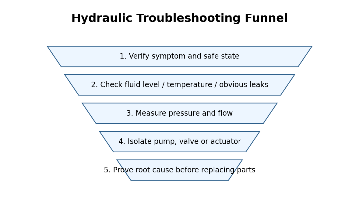
Figure 8. Simplified diagnostic view for 8. Separating Pump, Valve and Actuator Faults.
What the technician may observe
- all functions slow versus one function slow
- one direction weak versus both directions weak
- pressure high at pump but low at actuator
- pump pressure collapses only when one valve shifts
- cylinder drifts with valve centered
Diagnostic sequence
- Compare another actuator that uses the same pump. Compare the reading with a known-good baseline or the machine specification rather than relying on a generic value.
- Measure pump outlet pressure while the faulty function is loaded. Record the result before changing the next variable so the test actually narrows the fault.
- Measure work-port pressure close to the actuator. Compare the reading with a known-good baseline or the machine specification rather than relying on a generic value.
- Check return pressure for blocked or restricted exhaust paths. Record the result before changing the next variable so the test actually narrows the fault.
- Perform approved leakage/isolation tests on the actuator. Compare the reading with a known-good baseline or the machine specification rather than relying on a generic value.
- Swap only functionally identical valve sections when the design allows and the test is safe. Record the result before changing the next variable so the test actually narrows the fault.
How to interpret the measurements
Begin by asking whether the symptom affects the whole machine or only this function. If other functions sharing the same supply remain normal, a common pump or reservoir fault becomes less likely and the local valve, actuator, plumbing and mechanical load deserve more attention.
Next, compare pressure upstream and downstream while oil is actually flowing. A large pressure difference across a component means that component or passage is consuming hydraulic energy. If flow is low everywhere, investigate pump delivery, inlet conditions, speed and major internal leakage before blaming a local valve.
Finally, repeat the test at the condition that creates the complaint: hot oil, full load, a particular direction, low speed or rapid cycling. Hydraulic clearances, viscosity, pilot pressures and valve forces change with operating condition, so a static test may look normal while the production fault remains.
Corrective actions after the cause is proven
- Repair the proven boundary where pressure or flow is lost.
- Correct valve contamination before condemning a pump.
- Use leakage tests to confirm cylinder bypass.
- Restore any temporary test plumbing before production.
Common mistakes
- Adjusting the relief or compensator before recording the original setting and proving that the setting is wrong.
- Replacing a component because it is hot, even though the heat may be arriving from an upstream restriction or continuous bypass flow.
- Calling a problem “low pressure” when the actual complaint is low flow or excessive mechanical load.
- Testing only with cold oil when the production fault appears after the system reaches operating temperature.
Field rule: For 8. separating pump, valve and actuator faults, do not replace a component until one measurement or isolation test shows how it fails to perform its intended function.
Symptom-to-next-test table
| Observed condition | First useful test |
|---|---|
| All functions slow versus one function slow | Measure delivered flow and work-port pressure during motion. |
| One direction weak versus both directions weak | Measure pressure at pump and actuator under the actual load. |
| Pressure high at pump but low at actuator | Measure pressure at pump and actuator under the actual load. |
| Pump pressure collapses only when one valve shifts | Measure pressure at pump and actuator under the actual load. |
Field practice
Before leaving the machine, write down three numbers that would let another technician judge whether the repair truly restored normal operation. Good choices are usually operating temperature, a pressure at a defined machine state, and either flow or cycle time. This creates the baseline that makes the next fault faster to diagnose.
Continue the series
- Previous chapter: Hydraulic Building a Normal-Condition Baseline
- Next chapter: Hydraulic Temperature as a Troubleshooting Signal
- Browse all Hydraulic Troubleshooting chapters
Adapted from Hydraulic Troubleshooting for Maintenance Technicians, by Dovydas Kersys. © 2026 Dovydas Kersys. Featured cover image is an AI-generated editorial illustration.