A 0–10V signal looks simple.
Zero volts means minimum. Ten volts means maximum. Somewhere in the middle means, well, somewhere in the middle.
Easy.
Until the PLC shows 0% when the sensor is clearly active. Or the HMI value jumps around like a nervous rabbit. Or the analog value is stuck at 10V. Or the multimeter shows 5.2V, but the PLC says 83%. Then suddenly this “simple” signal becomes a small electrical mystery with too many suspects.
The good news: 0–10V analog troubleshooting is usually straightforward if you check it in the right order.
The bad news: if you skip the common wire, scaling, signal reference, or PLC input configuration, you can waste a silly amount of time.
So let’s go through it properly.
Not textbook-only. Real panel style.
What Is a 0–10V Signal?
A 0–10V signal is an analog voltage signal used to represent a changing value.
It may represent:
- Pressure
- Temperature
- Speed reference
- Valve position
- Damper position
- Level
- Flow
- Distance
- Load
- Tension
- Potentiometer position
- VFD speed command
- Sensor measurement
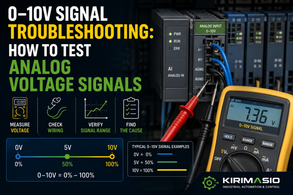
The basic idea is simple:
- 0V = minimum value
- 10V = maximum value
- 5V = about 50%
- 2.5V = about 25%
- 7.5V = about 75%
Example:
A pressure sensor is scaled from 0 to 10 bar.
- 0V = 0 bar
- 5V = 5 bar
- 10V = 10 bar
Another example:
A VFD receives a speed reference from 0–10V.
- 0V = 0% speed
- 5V = 50% speed
- 10V = 100% speed
That is the clean theory.
In real machines, you also have wiring, input resistance, shielding, PLC scaling, signal commons, sensor power, damaged cables, wrong parameters, and noise.
That’s where the fun starts.
Common Symptoms of 0–10V Signal Problems
A bad analog voltage signal can show up in different ways.
You may see:
- PLC analog value stuck at 0
- PLC analog value stuck at maximum
- HMI value jumping up and down
- Sensor output looks correct, but PLC value is wrong
- Multimeter reading does not match PLC reading
- Signal changes only in part of the range
- Value slowly drifts
- Reading changes when motor or VFD starts
- Reading changes when cabinet door moves
- VFD speed reference unstable
- Analog output gives voltage, but receiving device does not react
- PLC shows overflow or analog input fault
- Value is inverted: high signal shows low value
- 0–10V device only outputs 0–5V
- Signal drops when connected to PLC input
Each symptom points in a slightly different direction.
A value stuck at zero could be missing signal, wrong common, broken wire, dead sensor, wrong PLC input type, or scaling issue.
A jumping value often points to noise, shielding, grounding, loose wiring, unstable sensor power, or bad input filtering.
A correct voltage at the sensor but wrong PLC value often points to wiring between sensor and PLC, input configuration, or scaling.
And a signal that collapses when connected? That can mean the output device cannot drive the load, the input is wired incorrectly, or something is shorting the signal.
Analog signals are quiet little things. They don’t like abuse.
Safety Before Testing Analog Signals
Most 0–10V signals are low voltage, but they live inside control panels that may also contain dangerous voltages.
Before testing:
- Know what panel section you are working in
- Use a proper multimeter
- Avoid shorting signal terminals
- Do not bridge analog input terminals randomly
- Follow lockout/tagout rules when required
- Keep meter probes away from mains and motor terminals
- Check the electrical drawing
- Be careful near VFDs, contactors, and 400V circuits
A 0–10V signal wire may be harmless.
The terminal next to it may not be.
Panels love putting friendly and unfriendly voltages close together.
1. Identify the Analog Device
Before measuring, identify what device is producing or receiving the signal.
It may be:
- A pressure transmitter
- A temperature controller
- A level sensor
- A potentiometer
- A PLC analog output
- A VFD analog output
- A proportional valve controller
- A laser distance sensor
- A flow transmitter
- A load cell amplifier
- A speed controller
Then check the device label or datasheet.
You need to know:
- Supply voltage
- Output type
- Signal range
- Wiring type
- 0V/common terminal
- Load requirements
- Calibration range
- Whether output is 0–10V, 2–10V, 0–5V, or something else
Common signal ranges:
- 0–10V
- 2–10V
- 0–5V
- 1–5V
- ±10V
- 4–20mA, which is not voltage output
- 0–20mA, also not voltage output
This matters.
If you expect 0–10V but the sensor is actually 4–20mA, your readings will make no sense.
Wrong signal type = wrong troubleshooting path.
Simple as that.
2. Check Sensor or Transmitter Power
Most analog sensors need power before they can produce an output.
Common supply voltages:
- 24V DC
- 12V DC
- 10–30V DC
- 5V DC, less common in industrial panels
Check:
- +24V or supply terminal
- 0V/common terminal
- Fuse or electronic breaker
- Sensor connector
- Cable damage
- Voltage directly at sensor
- Voltage under load
Good signs:
- Correct supply voltage at the sensor
- Sensor LED on, if it has one
- Output changes when process value changes
- Supply remains stable
Bad signs:
- No supply voltage
- Wrong supply voltage
- Reverse polarity
- Supply drops when sensor connected
- Fuse blown
- Loose connector
- Sensor gets hot
- 24V present in cabinet but missing at field device
Measure at the sensor if possible, not only at the panel terminal.
A broken field cable can give you perfect 24V in the cabinet and nothing at the sensor.
The cabinet says yes.
The sensor says no.
The machine says fault.
3. Check the Signal Common / 0V Reference
This is one of the most common analog signal mistakes.
A 0–10V signal must be measured against the correct reference.
Usually that reference is:
- 0V
- Analog common
- Signal common
- AI common
- AGND
- MANA
- COM
The names depend on the device and PLC.
If the sensor output and PLC analog input do not share the correct common reference, the PLC may read wrong values, floating values, unstable values, or nothing at all.
Check:
- Sensor 0V connected to PLC analog common
- PLC input common wired correctly
- Analog common not broken
- No loose terminal
- No floating signal
- Correct common for the analog input channel
- Whether channels are isolated or non-isolated
Good signs:
- Signal voltage measured at PLC input matches sensor output
- Value is stable
- No floating voltage
- PLC reading matches meter reading after scaling
Bad signs:
- Signal changes when meter is connected
- Reading floats randomly
- PLC value jumps
- Meter reads voltage at sensor but not at PLC input
- Common wire loose
- Analog common missing
- Signal measured to earth looks different than measured to analog common
Do not measure the signal to a random cabinet ground and trust it.
Measure between the analog signal terminal and the analog common terminal.
The PLC reads the signal relative to its own reference, not relative to your best guess.
4. Measure the 0–10V Signal With a Multimeter
Use a digital multimeter set to DC voltage.
Measure between:
Signal output and signal common
For example:
- Sensor OUT to sensor 0V
- PLC AI+ to PLC AI common
- PLC analog output to output common
- VFD analog input terminal to analog common
Good readings:
- Around 0V at minimum process value
- Around 10V at maximum process value
- Smooth voltage change as process value changes
- Stable voltage when process is stable
Bad readings:
- Always 0V
- Always 10V
- Negative voltage when not expected
- Voltage jumps around
- Voltage slowly drifts for no process reason
- Voltage disappears when connected to PLC
- Voltage at sensor but not at PLC input
If the sensor output is 5V and the PLC input terminal also sees 5V, wiring is probably okay and the issue may be scaling or PLC configuration.
If the sensor output is 5V but the PLC terminal sees 0V, wiring or common is suspect.
If the sensor output itself is wrong, check sensor power, process condition, calibration, and sensor health.
Follow the voltage.
It tells the truth more often than people do.
5. Test at Both Ends of the Cable
A very useful analog signal test is measuring the signal at two places:
- At the sensor/output device
- At the PLC analog input terminal
Example:
At sensor:
OUT to 0V = 6.2VAt PLC input:
AI+ to AI COM = 6.2VThat is good. The signal is reaching the PLC.
But if you measure:
At sensor:
OUT to 0V = 6.2VAt PLC input:
AI+ to AI COM = 0.4VNow the signal is being lost or distorted between the sensor and PLC.
Possible causes:
- Broken signal wire
- Broken common wire
- Loose terminal
- Wrong terminal
- Cable damage
- Shield connected as signal by mistake
- Input shorted
- Wrong analog input configuration
- Bad connector
- Junction box issue
Do not assume a signal is reaching the PLC just because the sensor output is correct.
Measure at the PLC input.
That one check saves time.
6. Check If the PLC Analog Input Is Set for Voltage
Many PLC analog input modules can be configured for different signal types.
For example:
- 0–10V
- ±10V
- 0–5V
- 1–5V
- 4–20mA
- 0–20mA
- Resistance/RTD
- Thermocouple
If the module is configured for current input but wired to a voltage signal, the reading will be wrong or faulted.
Check:
- Hardware configuration
- DIP switches, if module uses them
- Software parameter settings
- Channel type
- Input range
- Wiring terminals
- Module diagnostics
- Scaling block settings
Good signs:
- Channel configured for 0–10V
- Wiring matches voltage input terminals
- Raw value changes with voltage
- No module diagnostic fault
Bad signs:
- Channel configured for 4–20mA
- Signal wired to current input terminal
- DIP switch in wrong position
- Raw value stuck
- Analog module fault
- Wrong input range selected
- Channel disabled
This often happens after replacing an analog module or copying PLC hardware configuration from another project.
The wires are right.
The parameter is wrong.
Still broken.
7. Check PLC Raw Analog Value
Before blaming scaling, check the raw analog value in the PLC.
Many PLCs convert 0–10V into a raw digital value.
Examples vary by brand and module, but a common idea is:
- 0V = raw minimum
- 10V = raw maximum
- 5V = around half scale
Some systems may use raw values like:
- 0 to 27648
- 0 to 32767
- 0 to 4095
- 0 to 10000
- 0 to 32000
Do not guess. Check your PLC analog module manual.
Good signs:
- Raw value changes when voltage changes
- Raw value is stable
- Raw value roughly matches expected voltage
- 5V gives about half of full raw range
Bad signs:
- Raw value stuck at zero
- Raw value stuck at maximum
- Raw value shows overflow/underflow
- Raw value jumps heavily
- Raw value changes but scaled HMI value does not
- Raw value is correct but engineering value is wrong
If the raw value is correct but the HMI value is wrong, the problem is scaling.
If the raw value is wrong, check wiring, signal, common, module configuration, and the sensor.
Raw value first. Fancy engineering units later.
8. Check Scaling in the PLC or HMI
A 0–10V input usually needs scaling.
Example:
Sensor range: 0–10 bar
Signal range: 0–10V
Then:
- 0V = 0 bar
- 5V = 5 bar
- 10V = 10 bar
But if the PLC scaling is wrong, the HMI value will be wrong even when the voltage is perfect.
Check:
- Input minimum voltage
- Input maximum voltage
- Raw minimum value
- Raw maximum value
- Engineering minimum
- Engineering maximum
- Unit conversion
- Decimal placement
- HMI tag scaling
- Inverted scaling
- Offset value
- Calibration correction
Common scaling mistakes:
- 0–10V sensor scaled as 4–20mA
- Wrong raw maximum
- Engineering range wrong
- Decimal point wrong
- 0–100% shown as 0–1000%
- HMI applies scaling again
- PLC and HMI both scale the same value
- Offset added twice
- Signal is 2–10V but scaled as 0–10V
Good signs:
- Raw value matches voltage
- Scaled value matches process
- HMI displays correct engineering units
- 5V gives about 50% of range
Bad signs:
- Meter shows 5V but HMI shows 80%
- Raw value correct but scaled value wrong
- HMI value inverted
- HMI decimal point wrong
- PLC scaling and HMI scaling both active
Scaling problems are very common.
Especially after copying code from another machine.
Copy-paste is fast.
Copy-paste also carries old mistakes with confidence.
9. Check for 2–10V Instead of 0–10V
Not every voltage signal starts at 0V.
Some devices use 2–10V.
In a 2–10V system:
- 2V = minimum
- 10V = maximum
- Below 2V may indicate fault or broken wire
This is common in some HVAC/control applications and actuator signals.
If the PLC expects 0–10V but the device outputs 2–10V, the reading may look offset.
Example:
A 2–10V damper position signal may show 2V when fully closed, not 0V.
That is normal for that device.
Good signs:
- Device datasheet confirms 2–10V
- PLC scaling uses 2V as minimum
- Reading makes sense across the range
Bad signs:
- PLC scaling assumes 0V minimum
- HMI shows 20% when device is physically at minimum
- Technician expects 0V and thinks sensor is faulty
- Signal below 2V triggers fault unexpectedly
Always confirm the actual signal range.
0–10V and 2–10V are close enough to confuse people and different enough to ruin scaling.
Annoying combination.
10. Check Potentiometer Wiring
Many 0–10V signals come from a potentiometer.
A potentiometer usually has three terminals:
- +10V reference
- Wiper/signal output
- 0V/common
The wiper gives a voltage between 0V and 10V depending on position.
Check:
- Reference voltage present
- 0V present
- Wiper output changes smoothly
- Correct terminal order
- No broken wiper
- Potentiometer resistance correct
- Mechanical coupling
- Direction of rotation
Good signs:
- Wiper voltage changes smoothly from near 0V to near 10V
- No jumps or dead spots
- PLC value follows movement
- Mechanical shaft turns correctly
Bad signs:
- Wiper stuck at 0V
- Wiper stuck at 10V
- Voltage jumps while turning
- Dead spots
- Direction reversed
- Loose shaft coupling
- Broken reference wire
- Wrong terminal wired as wiper
A worn potentiometer can create jumpy analog values.
The knob turns smoothly.
The signal does not.
Classic.
11. Check Analog Outputs From PLC or Controller
Sometimes the PLC is sending a 0–10V analog output to another device, such as a VFD or proportional valve.
In that case, troubleshoot the output side.
Check:
- PLC analog output enabled
- Correct output channel
- Output configured for voltage
- Output common wired correctly
- Output value in program
- Manual forcing/test mode, if safe
- Wiring to receiving device
- Receiving device input configuration
- Load impedance
- Cable shield
Good signs:
- PLC output voltage matches command
- Receiving device reads the signal
- Output changes smoothly
- Device reacts correctly
Bad signs:
- PLC output stays 0V
- Output stuck at 10V
- Voltage correct at PLC but not at device
- Voltage drops when connected
- Receiving device configured for current input
- Wrong analog input terminal on VFD
- Common missing
Example:
PLC analog output sends 5V.
At VFD analog input terminal, you measure 5V.
But the VFD speed reference stays 0%.
Then check VFD parameters.
The VFD may be set to keypad reference, fieldbus reference, or current input instead of voltage input.
The signal is there.
The drive is ignoring it.
Very rude, but very common.
12. Check the Receiving Device Input
A 0–10V signal can be perfect, but the receiving device may be configured wrong.
Receiving devices may include:
- PLC analog input
- VFD analog input
- Temperature controller
- Valve controller
- Positioner
- Servo controller
- Data acquisition module
- HMI analog input module
Check:
- Input mode: voltage or current
- Input range: 0–10V, 2–10V, ±10V
- Common terminal
- Scaling parameters
- Minimum/maximum values
- Filter settings
- Fault detection settings
- Control source selection
- Terminal enable settings
Good signs:
- Device input mode matches signal
- Device displays correct input voltage/value
- Scaling correct
- Control source set to analog input
Bad signs:
- Device set for 4–20mA input
- Analog input disabled
- Device using keypad/fieldbus instead of analog input
- Input common missing
- Signal wired to wrong terminal
- Fault detection trips below minimum voltage
A lot of VFD speed-reference problems are not wiring faults.
They are parameter faults.
The VFD sees the voltage, but it is not told to use that terminal as speed reference.
The voltage is knocking on the door. Nobody opened it.
13. Check Input Impedance and Load
A 0–10V output can only drive a certain load.
Most PLC analog inputs have high impedance, which is good. But if the signal is connected to too many devices, or one input has low impedance, the voltage may drop.
Symptoms:
- Signal is correct when disconnected
- Voltage drops when connected to receiving device
- One transmitter feeds multiple inputs and value becomes wrong
- Output device gets overloaded
- Signal does not reach full 10V
Check:
- Output device load rating
- Receiving input impedance
- Number of devices connected
- Parallel connections
- Short circuits
- Wrong current input connected to voltage output
Good signs:
- Voltage remains stable when connected
- Output device rated for connected load
- Only proper high-impedance inputs connected
Bad signs:
- Voltage collapses under load
- Multiple devices connected without buffer
- One device drags signal down
- Wrong terminal creates low resistance path
- Output overheats or faults
If one 0–10V signal must go to multiple devices, use a proper signal splitter or buffer if required.
Do not just twist three wires together and hope.
Hope is not a signal conditioner.
14. Check Noise and Shielding
Analog voltage signals are more sensitive to noise than many digital signals.
Noise can cause jumping values, drifting values, or false readings.
Common noise sources:
- VFD output cables
- Servo motor cables
- Large contactors
- Solenoid coils
- Welding equipment
- Heaters
- Poor grounding
- Long cable runs
- Bad shield connection
- Shared cable tray with power wires
- Poor 0V reference
Check:
- Shielded analog cable
- Shield connected correctly
- Cable separated from motor/VFD cables
- Cable not routed with high-current conductors
- Proper grounding
- Clean 24V supply
- Analog common wiring
- Input filtering
Good signs:
- Value stable when process is stable
- No jump when motors start
- Shield intact
- Cable routing separated from power
- Grounding follows panel standard
Bad signs:
- Value jumps when VFD runs
- Value changes when contactor switches
- Signal wire routed with motor cable
- Shield cut off
- Shield connected badly
- Analog common shared with noisy loads
- Random spikes
If the analog value changes when a motor starts, don’t immediately blame the sensor.
Look at cable routing and grounding.
The sensor may be fine. The signal is just being bullied by electrical noise.
15. Check Loose Terminals and Broken Wires
Analog signals can fail from simple wiring problems.
Check:
- Signal terminal
- Common terminal
- Sensor connector
- M12 pins
- Junction box terminals
- PLC analog input terminal
- Shield terminal
- Cable strain relief
- Broken ferrules
- Corrosion
- Moisture
- Oil contamination
Symptoms of wiring faults:
- Signal jumps when cable moves
- Reading changes when cabinet door opens
- Value drops to zero randomly
- Signal comes back after touching connector
- Reading depends on vibration
- Fault happens only sometimes
Good signs:
- Terminals tight
- Connector clean and dry
- Wire continuity good
- No movement-related changes
Bad signs:
- Loose terminal
- Broken wire inside insulation
- Oil/water in connector
- Corroded pins
- Cable damaged near moving parts
- Shield touching signal
- Wire barely clamped
Analog faults caused by loose terminals can look like noise, sensor failure, or PLC failure.
So yes, gently check the wires.
Not violently. Gently.
You’re troubleshooting, not arm-wrestling the cabinet.
16. Check Analog Input Filtering
Many PLCs allow software filtering for analog inputs.
Filtering smooths noisy values.
But too much filtering can make the value slow to respond.
Check:
- PLC analog filter time
- HMI smoothing
- Moving average blocks
- Sensor damping
- Controller input filter
- VFD analog filter
- Process response time
Good signs:
- Value is stable
- Response time is acceptable
- Filter matches process needs
Bad signs:
- Value jumps because no filtering
- Value responds too slowly
- HMI lags behind real process
- Filter hides short signal drops
- Multiple filters stacked together
If the signal is electrically noisy, fix wiring and shielding first.
Do not use filtering to hide a bad installation unless you understand the consequence.
Filtering is a bandage.
Sometimes useful.
Not always a cure.
17. Check Calibration
Sometimes the voltage signal is technically working, but the measurement is wrong.
Check:
- Sensor calibration
- Zero adjustment
- Span adjustment
- Process range
- Engineering units
- VFD analog input calibration
- PLC scaling offset
- Transmitter setup
- Mechanical position reference
Example:
A pressure sensor outputs 0–10V for 0–16 bar, but the PLC is scaled for 0–10 bar.
At 5V, the real pressure is 8 bar.
The PLC shows 5 bar.
The signal is not faulty.
The scaling is wrong.
Good signs:
- Sensor range matches PLC scaling
- Known process value matches HMI value
- Zero and span correct
- Calibration label/documentation matches setup
Bad signs:
- HMI value always off by fixed ratio
- Value has offset at zero
- Sensor range changed after replacement
- New sensor has different range
- Scaling copied from another machine
Sensor replacement causes this a lot.
Old sensor: 0–10V = 0–10 bar
New sensor: 0–10V = 0–16 bar
Same signal.
Different meaning.
That little detail can ruin a process.
18. Check for Broken Wire Detection Problems
One weakness of basic 0–10V signals is that 0V can mean two things:
- Real minimum value
- Broken wire or no signal
This is why some systems prefer 2–10V or 4–20mA signals, because they can detect a signal below the live-zero minimum as a fault.
With 0–10V, if the wire breaks and the input falls to 0V, the PLC may think the process is simply at minimum.
That can be dangerous depending on the application.
Check:
- Does PLC detect wire break?
- Is there fault logic for impossible values?
- Does sensor output have diagnostic signal?
- Should 2–10V or 4–20mA be used instead?
- Is the process safe if signal goes to zero?
Good signs:
- Fault detection included where needed
- Signal loss creates alarm
- Process responds safely
Bad signs:
- Broken wire reads as valid 0%
- No alarm on signal loss
- Critical process depends on raw 0–10V without diagnostics
This is not always a repair issue.
Sometimes it is a design issue.
And design issues are just faults waiting patiently.
Quick Checklist: 0–10V Signal Troubleshooting
Use this order.
- Identify the device
- Sensor, PLC output, VFD input, controller?
- Confirm signal type: 0–10V, 2–10V, 0–5V, ±10V?
- Check device power
- Correct supply voltage
- Fuse OK
- 0V present
- Voltage stable
- Check signal common
- Correct analog common
- Common connected to PLC/input
- No floating reference
- Measure voltage at source
- OUT to 0V/common
- Does voltage match process?
- Measure voltage at PLC/input
- AI+ to AI COM
- Same voltage as source?
- Any voltage lost in cable?
- Check PLC input configuration
- Voltage mode selected
- Correct range
- Channel enabled
- Correct terminals
- Check raw PLC value
- Raw count changes with voltage
- No overflow/underflow
- Stable reading
- Check scaling
- Correct raw min/max
- Correct engineering range
- No double scaling in HMI
- Check wiring
- Loose terminals
- Broken wires
- Wet connector
- Shield touching signal
- Check noise
- Cable separated from VFD/motor cables
- Shield connected correctly
- Grounding OK
- Check receiving device
- Input set to voltage
- Correct source selected
- Analog input enabled
- Check calibration
- Sensor range matches PLC scaling
- Zero/span correct
- Replacement sensor same range?
Good vs Bad Signs
| Check Area | Good Sign | Bad Sign |
|---|---|---|
| Sensor power | Correct stable supply voltage | Missing, low, or unstable supply |
| Signal common | Correct common/reference wired | Floating common, loose 0V |
| Signal at source | Voltage matches process | Stuck 0V, stuck 10V, unstable |
| Signal at PLC | Same as source voltage | Signal lost or different at PLC |
| PLC input setup | Channel set to 0–10V | Set to current, wrong range, disabled |
| Raw PLC value | Changes smoothly with voltage | Stuck, overflow, noisy |
| Scaling | HMI value matches real process | Wrong range, offset, double scaling |
| Wiring | Tight, clean, dry terminals | Loose, wet, broken, corroded |
| Shielding | Stable value, shielded cable | Jumping value, noise from VFD/motors |
| Receiving device | Uses analog voltage input | Set to keypad, fieldbus, or current input |
| Calibration | Sensor range matches setup | Replacement sensor has different range |
Example 1: PLC Shows 0%, But Sensor Outputs 5V
A pressure sensor should show around 50%.
The HMI shows 0%.
You measure at the sensor:
OUT to 0V = 5.0VGood. The sensor is outputting.
Then you measure at the PLC analog input:
AI+ to AI COM = 0VNow you know the signal is not reaching the PLC.
Possible causes:
- Broken signal wire
- Loose terminal
- Wrong terminal
- Cable damaged
- Common missing at PLC
- Junction box issue
The sensor is probably not the problem.
The signal disappears between sensor and PLC.
Follow the wire.
Example 2: Meter Shows 5V, HMI Shows 80%
A level sensor outputs 5V.
At the PLC input, you also measure 5V.
Raw PLC value is about half scale.
But the HMI shows 80%.
That means the signal and input are probably fine.
Now check scaling.
You find the HMI is applying its own scaling to a value already scaled in the PLC.
Cause: double scaling.
The analog signal was innocent.
The math was not.
Example 3: VFD Speed Jumps Up and Down
A PLC sends 0–10V speed reference to a VFD.
The motor speed randomly changes.
You measure the analog signal and see it jumping slightly when a large motor starts nearby.
The analog cable is routed in the same tray as VFD output cables.
Cause: electrical noise affecting the voltage reference.
Fix:
- Reroute analog cable away from motor/VFD cables
- Use shielded cable
- Check grounding
- Add proper filtering if needed
- Confirm analog common wiring
Do not solve this by randomly changing VFD speed parameters first.
The signal itself is dirty.
Example 4: New Sensor Reads Wrong Range
A pressure sensor was replaced.
The wiring is correct. The output is stable. PLC reads the voltage correctly.
But the pressure value is wrong.
Old sensor:
0–10V = 0–10 barNew sensor:
0–10V = 0–16 barCause: new sensor has a different measurement range.
The PLC scaling still assumes 0–10 bar.
Fix the scaling or use the correct sensor range.
Same 0–10V signal.
Different meaning.
A tiny detail with a big effect.
Example 5: Signal Drops When Connected to PLC
A controller outputs 0–10V.
When disconnected from the PLC input, the output measures correctly.
When connected, the voltage drops very low.
Possible causes:
- PLC channel wired as current input
- Input impedance too low
- Wrong terminal used
- Short on input wiring
- Multiple devices loading the output
- Faulty analog input channel
Cause is not automatically the controller.
The receiving input may be dragging the voltage down.
Disconnect and test carefully. Check input mode and wiring.
Common Mistakes When Testing 0–10V Signals
The first mistake is measuring to cabinet earth instead of analog common.
Measure to the correct reference.
The second mistake is assuming 0V always means the process is at minimum.
It may mean broken wire or dead sensor.
The third mistake is checking the signal only at the sensor.
Measure at the PLC too.
The fourth mistake is ignoring PLC input configuration.
A voltage signal wired into a current input will not behave nicely.
The fifth mistake is blaming the sensor when scaling is wrong.
If raw value is good, check the math.
The sixth mistake is routing analog cables beside VFD output cables.
That invites noise.
The seventh mistake is replacing a sensor without checking its measurement range.
A 0–10V output does not tell you what the engineering range is. The datasheet does.
Tools for 0–10V Signal Troubleshooting
Useful tools:
- Digital multimeter
- PLC programming software
- Electrical schematic
- Sensor datasheet
- Analog module manual
- Signal generator or process calibrator
- Oscilloscope, for noise problems
- Known-good cable
- Small screwdriver
- Terminal labels
- VFD/controller manual
- HMI scaling settings
A signal generator is especially useful because you can inject known voltages into the PLC input.
For example:
- Inject 0V and check HMI minimum
- Inject 5V and check midpoint
- Inject 10V and check maximum
If the PLC and HMI display correctly with a test signal, the PLC side is probably okay and the field sensor/wiring becomes more suspicious.
If the display is wrong even with a known test signal, check PLC configuration and scaling.
Very clean test.
Very underrated.
Final Thoughts
0–10V signal troubleshooting is mostly about being methodical.
A voltage signal needs four things:
Correct power.
Correct signal.
Correct common.
Correct scaling.
Start at the source. Measure the voltage. Then measure the same signal at the PLC input. Check the analog common. Confirm the input channel is configured for voltage. Look at the raw PLC value before trusting the HMI. Then check scaling, shielding, cable routing, and calibration.
Do not guess from the HMI value alone.
The HMI might be showing the wrong scaled value. The PLC might be configured for the wrong input type. The sensor might be fine. The cable might be broken. The common might be missing.
Follow the signal from the device to the PLC.
If the voltage is good at every step, the problem is probably configuration or scaling.
If the voltage disappears, find where.
Simple idea.
Still catches people out all the time.