A 24V DC fault can make a machine behave like it’s haunted.
Inputs flicker. Sensors randomly disappear. The PLC stays alive for a moment, then maybe it doesn’t. Relays chatter. Solenoid valves click once and then give up. The HMI shows alarms that don’t seem connected. And somewhere in the panel, a little 24V power supply sits there with its green LED blinking like it knows something you don’t.
Lovely.
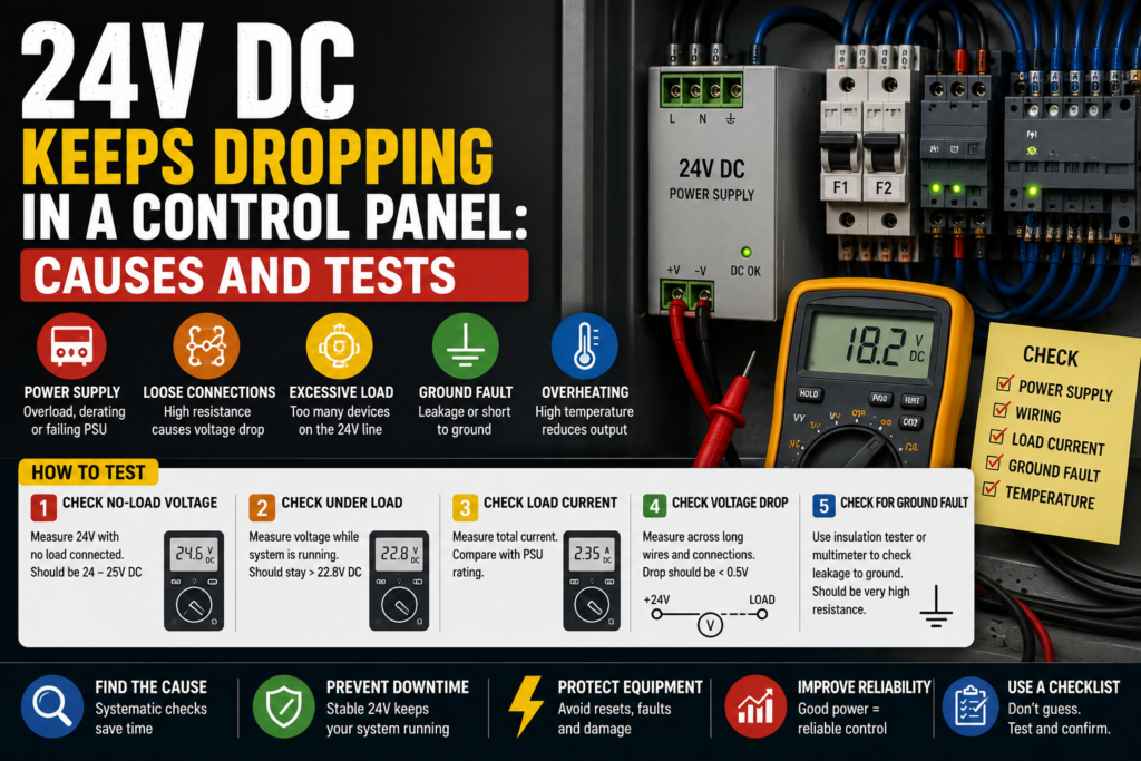
When 24V DC keeps dropping in a control panel, the problem is usually not “the PLC is bad.” More often, something is pulling the power supply down, the power supply is overloaded, a device is shorted, a wire is damaged, or the 24V supply is too weak for the load.
The trick is to find out whether the voltage drop is caused by the power supply itself, the load connected to it, or the wiring between them.
So let’s walk through it properly.
Not randomly. Not by replacing half the cabinet. Step by step.
What Does “24V DC Dropping” Actually Mean?
Before troubleshooting, define the symptom.
A 24V DC issue can show up in different ways:
- 24V drops to 0V
- 24V drops to 10–18V
- 24V is normal until the machine starts
- 24V drops only when a solenoid turns on
- 24V drops when several outputs energize together
- 24V power supply turns on and off repeatedly
- PLC inputs flicker
- Sensors lose power
- Relays chatter
- Remote I/O modules restart
- HMI or PLC communication drops
- Machine stops with strange alarms
Those details matter.
A voltage that slowly sags under load is different from a dead short that instantly pulls the supply down. A supply that cycles every second is different from a loose wire that drops voltage only when the cabinet vibrates.
Same headline. Different fault.
First: Measure the Voltage Correctly
Do not rely only on the power supply LED.
A green LED is useful, but it doesn’t prove the 24V is healthy under real machine load.
Use a multimeter and measure:
- Directly at the 24V power supply output terminals
- At the PLC power terminals
- At sensor supply terminals
- At remote I/O modules
- At solenoid valve connectors
- At relay coils
- At the farthest device in the circuit
Measure between +24V and 0V.
Not +24V to earth. Not a random terminal to cabinet ground unless the drawing tells you that is valid. Measure the actual circuit.
Good reading:
- Around 24V DC
- Often something like 23.5V to 24.5V
- Stable when the machine starts and outputs switch
Suspicious reading:
- 21V or lower
- Voltage drops when outputs turn on
- Voltage jumps up and down
- 24V at the power supply, but much lower at the device
- 24V disappears completely for a moment
Bad reading:
- 0V
- Supply cycling on/off
- Voltage collapsing under load
- Voltage present with no load, but disappears when connected
That last one is common. The power supply looks fine when unloaded, then collapses when the machine tries to run.
A little green LED, lying by omission.
1. Check If the 24V Power Supply Is Overloaded
Every 24V DC power supply has a current rating.
For example:
- 24V DC / 2.5A
- 24V DC / 5A
- 24V DC / 10A
- 24V DC / 20A
If the connected load needs more current than the power supply can provide, voltage may drop. Some power supplies go into current limiting. Some shut down. Some cycle on and off. Some get hot and act weird before failing completely.
Check the power supply label.
Then estimate or measure what it is feeding:
- PLC CPU
- PLC input modules
- PLC output modules
- Sensors
- Relays
- Contactors
- Solenoid valves
- HMI
- Safety relay
- Remote I/O
- Encoders
- Network switches
- Signal lamps
- Pneumatic valves
- Measuring devices
A panel that originally had enough 24V capacity can become overloaded after years of modifications.
One extra valve block here. A new HMI there. A few sensors added during an upgrade. Nobody recalculates the power supply. Then the machine starts dropping 24V during operation and everyone acts surprised.
Very normal. Very annoying.
How to test overload
Use a DC clamp meter if available.
Check:
- Total current coming from the 24V supply
- Current during machine idle
- Current during startup
- Current when solenoids energize
- Current when the fault happens
Good sign:
- Current stays below the power supply rating
- Voltage remains stable
- Power supply stays cool
Bad sign:
- Current is near or above the rated current
- Voltage drops as current rises
- Power supply gets very hot
- Supply enters hiccup mode
- Supply shuts down when outputs energize
If a 5A supply is feeding 7A of load, the fix is not mysterious. Either reduce the load, split the circuit, or install a correctly sized supply.
Do not just install a bigger supply without checking for shorts.
A bigger power supply can turn a small wiring problem into smoke.
2. Check for Short Circuits on the 24V Line
A short circuit is one of the main reasons 24V drops suddenly.
A direct short between +24V and 0V can pull the power supply down instantly. Some supplies shut off. Others limit current. Some try to restart again and again.
Possible short locations:
- Damaged sensor cable
- Crushed cable in machine frame
- Solenoid connector full of water
- Wrong wiring after maintenance
- Loose wire strand touching 0V
- Damaged M12 connector
- Cable rubbed through near moving parts
- Shorted relay coil
- Shorted solenoid coil
- Shorted input/output module
- Failed sensor
- Metal chips inside a connector
- Incorrect terminal jumper
Short circuits are often not inside the nice clean cabinet.
They are out on the machine, where oil, water, vibration, heat, and people with tools exist.
How to find a short
Start by checking circuit protection.
Look for:
- Tripped 24V electronic circuit breaker
- Blown DC fuse
- Power supply overload LED
- Output channel fault
- Warm cable
- Burning smell
- Repeated shutdown
Then isolate sections.
Common method:
- Turn power off.
- Disconnect one 24V branch at a time.
- Turn power on and check if voltage returns.
- Narrow the fault to one branch.
- Then narrow further to one device or cable.
Do this carefully and label wires if needed. Don’t create three new faults while looking for one.
Good sign:
- Disconnecting one branch restores stable 24V
- Fault is isolated to a specific cable or device
- Fuse stops blowing after faulty device is removed
Bad sign:
- Every branch seems to pull voltage down
- Power supply drops even with loads disconnected
- Short returns when machine moves
- Fault disappears when you open the cabinet door
That last one smells like a broken or loose wire affected by movement.
The machine is not haunted. The cable is probably flexing.
3. Check Devices That Switch On at the Moment of Voltage Drop
Timing matters.
If 24V drops only when a certain output turns on, follow that output.
Common troublemakers:
- Solenoid valves
- Relay coils
- Contactor coils
- Stack lights
- Brake coils
- Pneumatic valve islands
- Door locks
- Servo brake releases
- Heaters controlled through relays
- Clutch/brake units
- Buzzers
- Large indicator lamps
- Field devices with inrush current
Solenoid valves are especially suspicious.
A weak or shorted solenoid coil can drag down the 24V supply. A connector with moisture inside can do the same. Sometimes the valve works once, then the voltage drops and the whole machine gets confused.
Test the output device
When the fault happens, check:
- Which PLC output turned on?
- What device is connected to it?
- Does voltage drop immediately?
- Does the device coil get hot?
- Does the fuse trip?
- Does the output module show a fault?
- Does the power supply recover when the device is unplugged?
For a suspected coil, power off and measure resistance.
Good sign:
- Coil resistance is reasonable compared with a similar known-good device
- Connector is dry
- Device energizes without voltage drop
Bad sign:
- Coil resistance is very low
- Coil reads shorted
- Connector has oil or water
- Coil gets hot quickly
- Voltage drops when connector is plugged in
- Fuse trips when output turns on
A practical trick: compare the suspect solenoid coil with another identical coil on the same machine. Not perfect science, but useful.
If one coil measures wildly different from the rest, pay attention.
4. Check the 0V Common Side
People love chasing +24V.
But the 0V side can cause just as much trouble.
A bad 0V connection can make sensors flicker, PLC inputs behave strangely, and voltage measurements look confusing.
Check:
- 0V terminal blocks
- Common jumpers
- Broken 0V wires
- Loose terminals
- Corroded connections
- Shared commons between devices
- 0V connection to PLC input common
- 0V connection to output modules
- 0V reference for analog devices
A device needs a complete circuit. +24V going out means nothing if the return path is loose or broken.
Good vs bad 0V symptoms
Good signs:
- Solid 0V connection
- Low voltage difference between common points
- Inputs switch cleanly
- Devices operate normally
Bad signs:
- 24V present at device but it does not work
- Floating voltage readings
- Sensors flicker
- Inputs turn on weakly or randomly
- Voltage changes when other devices operate
- Different 0V terminals show unexpected voltage between them
Measure voltage drop on the 0V side under load.
A high voltage difference between 0V at the power supply and 0V at the device suggests bad wiring, overloaded common, loose terminal, or poor connection.
It sounds boring.
It is also exactly the kind of thing that wastes two hours.
5. Check Long Cable Runs and Voltage Drop
Sometimes the power supply is fine, but the voltage at the field device is too low.
Why?
Because the cable run is long, the wire is too thin, the current is high, or the terminal connections are poor.
Voltage drop can happen on both +24V and 0V conductors.
Common examples:
- Remote sensor boxes far from the panel
- Valve islands mounted on the machine
- Long cable chains
- Remote I/O stations
- Conveyors with field junction boxes
- Safety locks far from the cabinet
- Solenoids with long thin cables
You might measure:
- 24.2V at the power supply
- 23.8V at the cabinet terminal
- 20.5V at the valve connector when energized
That means the voltage is being lost along the path.
How to test voltage drop
Measure under load.
Do not measure only when everything is off. Voltage drop appears when current flows.
Check:
- Voltage at power supply during operation
- Voltage at terminal block
- Voltage at device connector
- Voltage across the load
- Voltage drop across +24V conductor
- Voltage drop across 0V conductor
Good sign:
- Device still receives close to 24V under load
- Minimal voltage difference between supply and device
Bad sign:
- Large voltage drop under load
- Device receives too little voltage
- Cable or terminal heats up
- Relay chatters
- Solenoid weakly clicks
- Sensor resets
Possible fixes include thicker wires, shorter cable path, separate supply closer to load, better terminals, or splitting loads properly.
Do not solve voltage drop by randomly increasing power supply voltage unless the equipment allows it. Some supplies can be adjusted slightly, but field devices still have maximum voltage limits.
More voltage is not always better. Sometimes it is just a faster way to damage sensors.
6. Check the 24V Power Supply Itself
Power supplies fail too.
Not every voltage drop is caused by the load. Sometimes the power supply is old, overheated, undersized, full of dust, installed with poor ventilation, or simply dying.
Check:
- Output voltage with no load
- Output voltage under load
- Ripple/noise, if you have the right meter/scope
- Temperature
- Ventilation space
- Dust buildup
- Input voltage
- Power supply status LEDs
- Overload indicator
- Age and environment
- Terminals and wiring
A failing power supply may work when cold and fail when warm.
Classic.
The machine starts fine in the morning, then after one hour of production the 24V begins dropping. Everyone blames the machine cycle. But the supply is cooking inside the panel.
Good signs
- Stable 24V under load
- Supply not overheating
- Enough current capacity
- Clean ventilation
- Input voltage correct
- No cycling or overload indication
Bad signs
- Voltage low even with light load
- Voltage unstable
- Power supply very hot
- Supply cycles on/off
- Output drops after warming up
- Burnt smell
- Fan failed, if fan-cooled
- Input voltage unstable
If possible, test with a known-good power supply of correct rating.
But don’t just replace it and call it done unless you also check load current. A new supply may survive better, but if the circuit is overloaded or shorted, the real fault remains.
7. Check Input Voltage to the Power Supply
A 24V power supply cannot produce stable 24V if its input supply is bad.
Check the AC input side:
- Correct input voltage
- Breaker or fuse feeding supply
- Loose terminals
- Phase and neutral, if single-phase
- L1/L2 if line-to-line supply
- Control transformer output
- Voltage dips when machine starts
- Bad contactor or relay feeding the supply
For example, a 230V AC input power supply may drop its 24V output if the 230V input dips badly.
Good sign:
- Input voltage stays within the power supply allowed range
- No loose input terminals
- No AC supply dips during operation
Bad sign:
- Input voltage low
- Input drops when machine starts
- Loose neutral
- Control transformer overloaded
- Fuse holder bad
- Breaker contact weak
- Supply input disappears briefly
If the 24V drops at the same time as the input voltage drops, the problem may be upstream.
Don’t blame the 24V supply for bad feeding voltage.
That’s like blaming a water tap when the main pipe is shut.
8. Check PLC Outputs and Output Modules
A PLC output module can also be involved.
Some output modules have short-circuit protection. If a connected load is shorted, the module may shut down the channel or pull down the supply.
Check:
- Output channel fault LEDs
- Module diagnostics
- Output common voltage
- Load current
- External fuse
- Wiring from output to device
- Device coil
- Output group supply
- Shared output commons
A common situation:
One faulty solenoid is connected to a PLC output. When the PLC turns it on, the 24V drops or the output module reports a fault. The rest of the machine then stops because sensors and relays lose power.
Good sign:
- Output turns on without voltage drop
- Channel diagnostics normal
- Load current within rating
Bad sign:
- Output fault appears
- Voltage drops only when specific output turns on
- Output module gets hot
- Channel shuts down
- Fuse trips
- Solenoid or cable shorted
If one output causes the voltage drop, don’t replace the whole PLC module first.
Disconnect the load and test the circuit. The module may only be reacting to a short outside the cabinet.
9. Check Sensors and Field Wiring
Sensors are small, but many of them share the same 24V supply.
A damaged sensor cable can pull down the whole branch.
Common sensor faults:
- Brown and blue wires shorted
- Signal wire shorted to +24V or 0V
- Cable crushed
- M12 connector wet
- Sensor internally shorted
- Metal chips in connector
- Wrong sensor type installed
- Sensor cable damaged by moving parts
- Junction box full of water
If the fault appears after machine movement, check sensors mounted on moving sections.
If the fault appears after cleaning, check wet connectors.
If the fault appears after maintenance, check recently touched cables.
There is always a “recently touched” cable. Always.
Well, almost always.
How to isolate sensor branches
Look at the electrical drawing and find how sensors are grouped.
Then disconnect one group at a time:
- Sensor supply branch 1
- Sensor supply branch 2
- Junction box cable
- M12 distribution box
- Remote I/O sensor supply
- Specific machine section
When 24V returns, you found the faulty branch.
Then go device by device.
It is not glamorous work, but it works.
10. Check Electronic Circuit Breakers and Fused Terminals
Many modern panels use 24V electronic circuit breakers or fused distribution terminals.
These devices split the 24V into protected channels.
Check:
- Which channel tripped
- Channel current
- Trip history
- LED status
- Manual reset requirement
- Load connected to that channel
- Correct current setting
- Fuse size
- Fuse continuity
- Voltage before and after protection
Good signs:
- Each channel has stable voltage
- Current below setting
- No trips
- Fault isolated to one channel
Bad signs:
- Channel repeatedly trips
- Voltage before breaker but not after
- Fuse blown
- Fuse blows again
- Current setting too low
- Wrong device connected to channel
- Channel overloaded
Electronic breakers are helpful because they prevent one shorted field device from killing the entire 24V supply.
But only if the panel is wired properly.
If everything is connected to one protection channel, then one bad sensor can still drag the whole system down. That is not the breaker’s fault. That is poor distribution.
11. Check Inrush Current
Some devices draw a short high current when first energized.
This is called inrush current.
Possible sources:
- HMIs
- Industrial PCs
- Ethernet switches
- Capacitive loads
- Valve islands
- DC/DC converters
- LED lights
- Relays and contactors
- Brake coils
- Sensors with internal electronics
If too many devices start at the same time, the 24V supply may dip.
This can happen at machine power-up or when enabling a group of outputs.
Good sign:
- Power supply handles startup without large voltage drop
- Devices power up normally
- No repeated restart loop
Bad sign:
- 24V drops at power-up
- PLC restarts
- HMI reboots
- Remote I/O resets
- Power supply hiccups
- Fault happens only when many devices energize together
Possible fixes:
- Use a higher-rated power supply
- Split loads into separate supplies
- Stagger device startup
- Add proper buffer module/UPS, if needed
- Separate PLC/control supply from actuator supply
Splitting supplies is often smart.
One supply for PLC and sensitive electronics. Another supply for solenoids, relays, and field loads.
Because honestly, letting one shorted solenoid reboot your PLC is just asking for a bad afternoon.
12. Separate Control Supply and Actuator Supply
A good control panel often separates 24V loads.
For example:
- 24V supply for PLC, HMI, communication, sensors
- 24V supply for solenoids, relays, contactor coils, brakes
- Separate protected branches for field devices
- Electronic circuit breakers for groups
Why?
Because actuator loads are noisy and fault-prone. Solenoids short. Cables get crushed. Valve connectors fill with oil. Relays and coils create spikes.
Sensitive devices like PLCs and HMIs prefer stable power.
If everything is on one 24V supply, a fault on one solenoid can drop the PLC and make troubleshooting harder.
Good design:
- PLC supply remains stable
- Field branch trips separately
- Fault is easier to isolate
- HMI stays on and shows diagnostics
Bad design:
- One field short drops everything
- PLC restarts
- HMI goes black
- Fault history disappears
- Troubleshooting becomes guesswork
If your panel regularly has 24V drop problems, the design may need improvement, not just repair.
13. Check for Inductive Spikes and Missing Suppression
Coils are inductive loads.
When a relay coil, solenoid coil, contactor coil, or brake coil switches off, it can create a voltage spike if not suppressed properly.
This may not always “drop” the 24V, but it can cause PLC resets, output module faults, communication errors, or weird intermittent behavior.
Check for suppression on:
- Relay coils
- Solenoid valves
- DC contactor coils
- Brake coils
- Clutch coils
- Large inductive devices
Suppression methods may include:
- Flyback diode
- Varistor
- RC snubber
- Built-in coil suppression
- Suppressor plug
Good signs:
- Coils have proper suppression
- Output modules stable
- PLC does not reset during switching
- No strange input flicker
Bad signs:
- PLC resets when coil turns off
- Output module faults
- Communication drops during switching
- Relays arc heavily
- No suppression on large DC coils
Be careful when adding suppression. The type matters, and polarity matters for DC diode suppression. A diode installed backwards across 24V can create a direct short.
That’s one of those “fixes” that immediately becomes the next fault.
14. Check Temperature Inside the Panel
Heat can make power supplies and electronics unstable.
Check:
- Cabinet temperature
- Power supply temperature
- Ventilation
- Fan filters
- Cooling fans
- Heat from drives/contactors
- Dust buildup
- Sun exposure
- Enclosure sealed too tightly
- Components mounted too close together
A 24V supply may work fine with the panel door open and fail when the door is closed.
Why?
Because it overheats.
Good sign:
- Panel temperature within component limits
- Power supply has ventilation space
- Filters clean
- Fans working
Bad sign:
- Power supply too hot to touch
- Voltage drops after running for a while
- Fault disappears after cooling
- Fan not working
- Filters blocked
- Components packed tightly together
If the voltage drop happens after 30 minutes or 2 hours, not immediately, heat becomes more suspicious.
Heat faults are patient. They wait until you start trusting the machine again.
Then they return.
15. Check Recent Changes
Always ask what changed.
Seriously.
Many 24V problems appear after:
- New sensor installed
- Solenoid replaced
- Cable repaired
- Machine washed
- Panel modified
- HMI added
- PLC output rewired
- Extra light installed
- Valve island expanded
- Remote I/O added
- Maintenance work done
- Mechanical adjustment made
- Cable chain serviced
A new component may be wired wrong. A replacement sensor may have different pinout. A cable may be pinched after repair. A new load may exceed the power supply rating.
Good troubleshooting question:
What was touched before the fault started?
People may say “nothing.”
Then after five minutes: “Well, we changed one sensor yesterday.”
There it is.
The “nothing” sensor.
Quick Checklist: 24V DC Keeps Dropping
Use this order when troubleshooting.
- Measure the 24V properly
- At power supply
- At PLC
- At device
- Under load
- Check power supply rating
- Current rating
- Load current
- Overload LED
- Temperature
- Check for shorts
- Blown fuses
- Tripped electronic breakers
- Damaged cables
- Wet connectors
- Shorted coils
- Isolate branches
- Disconnect one branch at a time
- Find which branch restores voltage
- Narrow to one device or cable
- Check devices switching at fault time
- Solenoids
- Relays
- Contactors
- Brakes
- Valve islands
- Check 0V common
- Loose terminals
- Broken commons
- Missing jumpers
- Voltage drop on return path
- Check long cable voltage drop
- Measure at far device
- Measure under load
- Check wire size and terminals
- Check power supply input
- AC input stable
- Fuse/breaker OK
- No loose terminals
- No input voltage dip
- Check PLC/output modules
- Output fault LEDs
- Output common supply
- Channel overload
- Shorted load
- Check heat and environment
- Panel temperature
- Ventilation
- Moisture
- Dust
- Oil contamination
- Check recent changes
- Replaced sensor
- New solenoid
- Modified wiring
- Washed machine
- Added load
Good vs Bad Signs
| Check Area | Good Sign | Bad Sign |
|---|---|---|
| Power supply output | Stable around 24V DC | Drops, cycles, unstable voltage |
| Load current | Below supply rating | Near or above rating |
| 24V branches | Each branch stable | One branch pulls voltage down |
| Sensors | Powered, signals stable | Flickering, shorted cable, wet connector |
| Solenoids | Energize normally | Coil hot, low resistance, voltage drop |
| 0V common | Solid return path | Loose common, floating readings |
| Cable voltage drop | Small drop under load | Large drop at far device |
| Protection | Breakers/fuses normal | Repeated trips or blown fuses |
| PLC outputs | No channel faults | Output fault when load turns on |
| Panel temperature | Normal temperature | Power supply overheats |
| Input voltage | Stable AC input | Input dips or loose feed |
Example 1: 24V Drops When a Solenoid Turns On
A machine runs normally until one pneumatic cylinder should move.
At that moment, the 24V drops, PLC inputs flicker, and the machine faults.
You check the PLC output and see one solenoid output turns on at the exact same time.
Power off. You disconnect the solenoid plug. Power on. Run the test again.
Now the 24V stays stable.
You measure the coil resistance and compare it with another identical solenoid. The suspect coil reads much lower.
Cause: shorted solenoid coil pulling down the 24V supply.
The PLC was innocent.
Again.
Example 2: 24V Good at Supply, Low at Sensor Box
The power supply output is 24.1V.
But a remote sensor box at the end of the machine only gets 19.8V when several sensors and valves are active.
At the cabinet terminal, voltage is still good.
You measure along the cable and find a large voltage drop on the 0V return conductor.
Cause: loose 0V terminal in a junction box.
The supply was fine. The field wiring was not.
This is why measuring only at the power supply can fool you.
Example 3: Power Supply Cycles On and Off
The 24V power supply turns on for one second, then off, then on again.
Classic hiccup behavior.
You disconnect the field 24V branches one by one. When one branch is removed, the supply becomes stable.
That branch feeds several M12 sensors near a moving arm.
You inspect the cables and find one crushed sensor cable shorting +24V to 0V when the arm moves.
Cause: damaged moving cable.
Not bad PLC. Not bad HMI. Not black magic.
Just a cable that had enough.
Example 4: 24V Drops After 30 Minutes
Machine starts fine cold.
After about 30 minutes, the 24V begins dropping and remote I/O modules restart.
The power supply is very hot. Panel fan filter is blocked with dust. Cabinet temperature is high.
After cleaning the filter and improving ventilation, the supply stays stable. But because the power supply had been overheated many times, replacement may still be smart.
Cause: overheating 24V power supply.
Heat faults like to pretend they are random.
They are not.
Common Mistakes When Troubleshooting 24V DC Drops
The first mistake is checking voltage only with no load.
A weak supply or bad connection may look fine until current flows.
The second mistake is measuring only at the power supply.
You need to measure at the device too.
The third mistake is replacing the power supply without checking for short circuits.
A new supply may drop too if the load is still faulty.
The fourth mistake is ignoring the 0V side.
A broken common can create strange symptoms.
The fifth mistake is assuming small sensors cannot cause big problems.
One shorted sensor cable can pull down a whole 24V branch.
The sixth mistake is putting PLC, HMI, sensors, solenoids, brakes, and field devices all on one unprotected supply.
It may work.
Until it doesn’t.
The seventh mistake is forgetting recent changes. The fault often starts exactly where someone was working.
Funny how that happens.
Tools for 24V DC Troubleshooting
Useful tools:
- Digital multimeter
- DC clamp meter
- Electrical drawings
- Fuse tester or continuity tester
- Known-good 24V supply, for testing
- Insulated screwdrivers
- Terminal markers
- Thermal camera, if available
- Spare fuses
- Cable tester
- Sensor/solenoid datasheets
The most useful tool, though, is still a careful method.
Measure. Isolate. Compare. Narrow down.
Don’t attack the whole panel at once.
Final Thoughts
When 24V DC keeps dropping in a control panel, think in three directions:
Supply. Load. Wiring.
The power supply may be too small, weak, overheated, or failing.
The load may be too high, shorted, wet, damaged, or switching with heavy inrush.
The wiring may have loose terminals, voltage drop, broken commons, crushed cables, or bad connectors.
Start by measuring the 24V at the power supply and at the actual device, under load. Then isolate branches. Watch what happens when outputs energize. Check solenoids, sensors, field cables, fuses, and 0V commons.
The fault is usually not mysterious. It only looks mysterious when the whole 24V system collapses and every alarm appears at once.
Follow the voltage.
Find where it disappears.
That’s the job.