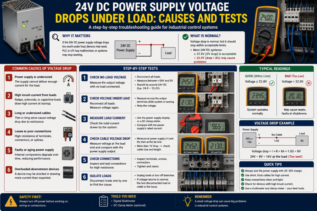
A 24V DC power supply measures perfectly with nothing connected. You switch on a solenoid, contactor, HMI or group of sensors—and the voltage suddenly falls.
Perhaps it drops to 20V for a moment. Maybe it collapses to 10V and repeatedly recovers. In worse cases, the PLC restarts and every output switches off before the voltage returns.
This does not automatically mean the power supply is defective.
The load may be drawing too much current. A damaged cable could be creating a partial short circuit. The voltage may be correct at the power supply but much lower at the device because of undersized conductors or a loose terminal.
The quickest diagnosis comes from measuring voltage at several points while the fault is actually present.
What Does a Voltage Drop Under Load Mean?
A regulated 24V DC power supply should keep its output close to the set voltage while the current remains within its specified operating range.
When the required current becomes too high, the supply may:
- Limit its output current
- Reduce the output voltage
- Shut down temporarily
- Attempt repeated restarts
- Enter a latched shutdown state
- Overheat and reduce its available output
The exact behaviour depends on the power supply design. Siemens supplies, for example, may use current limiting, shutdown or periodic restart behaviour during overload and short-circuit conditions. Some models also provide temporary overload capacity above their continuous rating.
The pattern of the voltage drop can therefore provide a useful clue.
Work Safely Before Testing
Although the output is only 24V DC, the input side of the power supply may contain 120V, 230V or 400V AC.
Before tightening connections, removing wires or testing resistance:
- Isolate and lock out the incoming supply
- Verify the absence of voltage
- Wait for internal capacitors to discharge
- Prevent machinery from moving unexpectedly
- Follow the panel manufacturer’s safety procedure
Live measurements should only be performed by qualified personnel using correctly rated instruments.
Step 1: Measure at the Power Supply Output
Place the multimeter probes directly on the power supply’s positive and negative output terminals.
Record the voltage in two conditions:
- With the load switched off
- While the problem load is operating
This first test divides the fault into two broad categories.
Voltage Drops at the Power Supply Terminals
The likely causes include:
- Excessive total load
- Short circuit
- High starting current
- Low AC input voltage
- Thermal derating
- A defective or undersized power supply
Voltage Remains Stable at the Supply but Drops at the Load
The likely causes include:
- Undersized cables
- Long cable runs
- Loose terminals
- Damaged fuse holders
- High-resistance circuit protection
- Poor return-path connections
Do not measure only positive to protective earth. Always measure between the actual positive and negative conductors feeding the load.
Step 2: Measure the Total Load Current
Read the rated output current printed on the power supply.
A unit marked 24V DC, 5A can continuously provide approximately 120W under its specified operating conditions.
Now measure the actual DC load current using:
- A DC clamp meter
- A suitable panel ammeter
- The power supply’s diagnostic output
- An electronic protection module
- A multimeter connected in series, when safe and within its current rating
Do not place a multimeter set to current directly across the output terminals. That creates a short circuit and will usually blow the meter fuse.
Compare the measured current with the supply rating. Include loads that operate only occasionally, such as:
- Solenoid valves
- Contactors
- Relays
- Motor brakes
- DC motors
- HMI panels
- Industrial computers
- Remote I/O stations
- Field devices powered through long cables
The normal operating current may look acceptable until several devices energise at the same time.
Step 3: Check for Overload or Current Limiting
When a switching power supply reaches its current limit, it can no longer maintain both the demanded current and 24V output.
The result may be a steady lower voltage or a repeating cycle:
- The load switches on.
- Current exceeds the limit.
- The output voltage collapses.
- The power supply shuts down.
- The load switches off.
- The supply restarts.
- The process repeats.
This is often called hiccup or restart-mode protection.
Watch the LEDs on the supply. Depending on the model, they may indicate:
- DC OK
- Overload
- Current limiting
- Shutdown
- Output undervoltage
Some industrial supplies offer temporary power reserves. Siemens’ PSU6200 range, for example, can provide 150% of rated current for up to five seconds per minute, while Phoenix Contact offers static and dynamic boost functions on selected QUINT supplies. These features help start demanding loads, but they do not make a permanently undersized supply acceptable.
Step 4: Disconnect Load Branches One at a Time
If several devices share the same supply, isolate the problem systematically.
Switch off the panel and disconnect one outgoing 24V branch at a time. Re-energise the system after each approved change and watch the output voltage.
Typical branches might include:
- PLC and remote I/O
- HMI
- Sensors
- Solenoid valves
- Contactors and relays
- Safety circuits
- Field junction boxes
If the voltage becomes stable after one branch is removed, investigate that branch rather than replacing the power supply immediately.
A branch can be overloaded because of one failed device, damaged wiring or simply too many healthy devices connected together.
Step 5: Look for Short Circuits and Partial Shorts
A direct short circuit will usually force the power supply into protection immediately.
A partial short can be less obvious. It may draw enough current to pull the voltage down without operating a fuse or electronic circuit protector.
Possible causes include:
- Crushed sensor cables
- Water inside a junction box
- Damaged solenoid coils
- Reversed field wiring
- Loose wire strands touching another terminal
- A failed surge suppressor
- Incorrectly connected PNP or NPN devices
- Damaged insulation inside a cable chain
After isolating the supply and disconnecting sensitive equipment, check the resistance between 24V and 0V on the suspicious branch.
A low reading does not always prove a short because electronic devices and capacitors can affect the measurement. Observe whether the resistance rises as capacitors charge, and compare the result with a known-good circuit where possible.
Step 6: Check Starting and Inrush Current
Some 24V devices draw far more current during startup than during normal operation.
Common examples include:
- DC motors
- Large contactor coils
- Solenoid valves
- Motor brakes
- Capacitive electronic loads
- HMI panels
- Industrial computers
- Multiple PLC modules energised together
A power supply may operate normally after the equipment has started but fail to deliver the brief initial current peak.
If the voltage drops only for a fraction of a second, use:
- A meter with minimum-value capture
- An oscilloscope
- A power analyser
- Power-supply diagnostic software
- A current monitor with fast recording
A normal multimeter display may refresh too slowly to show the deepest part of the dip.
When many electronic loads are connected, consider switching branches on sequentially rather than energising everything at once. Siemens selectivity modules support sequential connection partly to reduce total inrush demand on a 24V system.
Step 7: Measure Voltage Drop in Both Conductors
Voltage can be lost in the positive conductor, the negative return or both.
With the load operating, measure:
Positive-Side Drop
Place one probe on the power supply’s positive terminal and the other on the load’s positive terminal.
Negative-Side Drop
Place one probe on the load’s negative terminal and the other on the power supply’s negative terminal.
Each measurement shows the voltage being lost along that conductor.
Move the probes through the circuit to test individual components:
- Fuse
- Circuit breaker
- Electronic circuit protector
- Relay contact
- Terminal block
- Connector
- Cable section
A healthy closed connection should have very little voltage across it. A large voltage drop across one terminal, fuse holder or contact identifies unwanted resistance.
Step 8: Check Cable Length and Cross-Section
Long or undersized conductors produce voltage drop as current increases.
That is why a remote valve may work when tested alone but fail when several nearby valves energise. The current rises, and so does the voltage lost in the cable.
Mean Well warns that excessive line voltage drop can leave insufficient voltage at the load. Siemens also offers adjustable output voltage on selected SITOP units specifically to compensate for voltage loss on long conductors.
Increasing the supply setting is not a substitute for properly sized wiring.
If the power supply is raised to 26V so that a remote load receives 24V, devices mounted close to the supply may also receive 26V. Confirm that every connected device can tolerate the adjusted voltage.
The better solution may be:
- Larger conductors
- A shorter cable route
- Separate supply branches
- A local DC/DC converter
- A distributed power supply near the load
Step 9: Inspect Terminals and Protection Devices
High-resistance connections often behave normally when little current is flowing.
Under load, they heat up and drop voltage.
Inspect:
- Power-supply output terminals
- Distribution terminals
- Fuse holders
- Electronic circuit-protection channels
- Disconnect switches
- Plug connectors
- Field junction boxes
- Negative common bars
Look for:
- Discoloured plastic
- Darkened copper
- Loose screws
- Corrosion
- Damaged ferrules
- Partially inserted conductors
- Several wires forced into an unsuitable terminal
Thermal imaging can help locate a poor connection while the circuit is loaded, but it does not replace electrical measurement.
Step 10: Check the AC Input Voltage
The DC output problem may begin on the AC side.
Measure the input voltage at the power supply while the output is loaded. Check it against the permissible input range shown on the product label or datasheet.
Possible input-side faults include:
- Low mains voltage
- A loose neutral
- A failing breaker
- A damaged fuse holder
- Incorrect voltage-selector position
- An undersized control transformer
- Excessive voltage drop in the AC wiring
- A generator that cannot handle the load step
Some power supplies can bridge very short input interruptions using stored energy, but longer or repeated input dips will eventually appear at the 24V output.
Step 11: Check Temperature and Ventilation
A power supply’s full rated current may only be available below a specified ambient temperature.
Above that point, output capacity is reduced through derating.
For example, selected Phoenix Contact supplies specify output-current derating of 2.5% per degree above 60°C. The exact limit varies by model, mounting position and installation conditions.
Check for:
- Blocked ventilation openings
- Insufficient spacing
- High panel temperature
- Installation beside hot VFDs or braking resistors
- Incorrect mounting orientation
- Dust buildup
- Failed enclosure fans
- Direct sunlight on outdoor panels
A supply that works with the panel door open but fails when the cabinet becomes hot is strongly pointing toward a thermal problem.
Step 12: Test the Power Supply With a Known Load
Disconnect the machine loads and test the supply using a suitable electronic load or known resistive load.
Increase the current gradually while monitoring:
- Output voltage
- Output current
- Temperature
- Status LEDs
- AC input voltage
Do not improvise a high-power load unless you understand the heat and current involved. A 24V load drawing 5A consumes 120W and becomes extremely hot.
If the power supply cannot maintain its specified output with a controlled load, correct input voltage and proper cooling, it is likely defective.
Fast Troubleshooting Sequence
- Measure directly at the power supply output.
- Measure at the affected load.
- Record total output current.
- Watch for current-limit or overload indications.
- Disconnect outgoing branches one at a time.
- Check for short circuits and damaged field devices.
- Measure startup current and voltage dips.
- Test voltage drop in both positive and negative conductors.
- Inspect terminals, fuses and cable sizing.
- Measure the AC input under load.
- Check ambient temperature and ventilation.
- Test the supply with a known controlled load.
Final Thoughts
A 24V power supply that drops voltage under load is usually telling you that current cannot reach the load under the required conditions.
The reason may be an overloaded supply, a short circuit, high inrush current, hot operating conditions or resistance somewhere in the wiring.
Measure at the power supply first. Then measure at the load. That simple comparison quickly reveals whether the voltage is collapsing inside the supply or being lost along the cable.
Do not replace the power supply until you know which of those two problems you actually have.