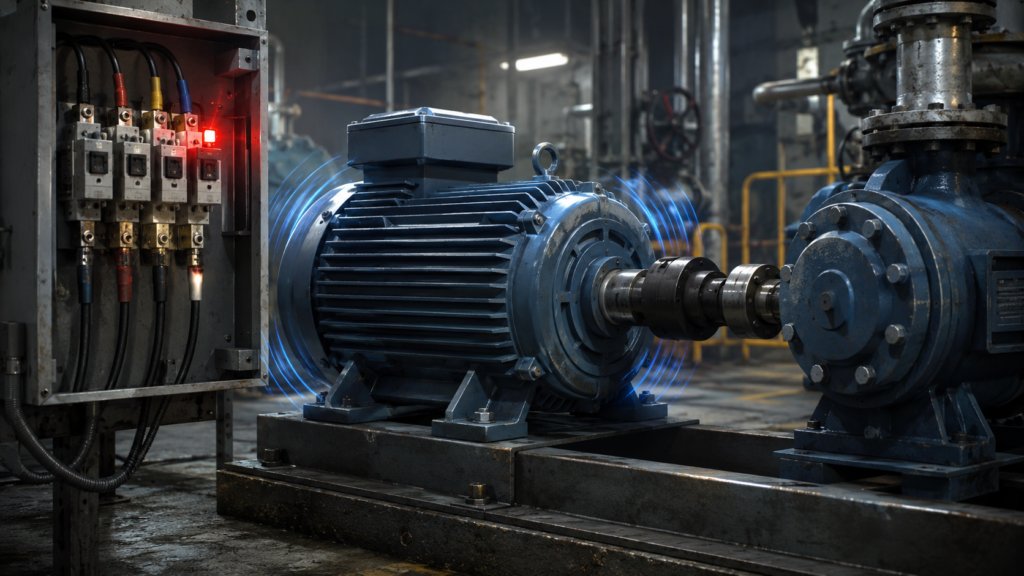
A three-phase motor should normally begin rotating almost as soon as power is applied.
If it only hums, vibrates or sits motionless while drawing current, something is preventing the rotating magnetic field from producing enough starting torque—or the motor shaft is physically unable to move.
This condition should be treated seriously.
A stationary motor has little or no cooling airflow and may draw very high current. If it remains energised, the windings can overheat quickly, the overload relay may trip, and the motor or starter may suffer permanent damage.
Do not leave it humming while waiting to see whether it eventually starts.
The most common causes of a 3 phase motor humming but not turning are:
- a missing supply phase;
- a jammed mechanical load;
- a burned or open motor winding;
- a failed contactor pole;
- low or unbalanced voltage;
- incorrect star/delta links;
- a mechanical brake that does not release;
- a VFD fault or incorrect drive configuration.
The fastest diagnosis usually comes from separating the problem into three areas:
- Mechanical: Can the shaft and driven machine rotate?
- Electrical supply: Do all three phases reach the motor?
- Motor and control: Are the windings, starter and parameters correct?
Quick Troubleshooting Table
| Symptom | Most likely causes |
|---|---|
| Motor hums loudly and does not move | Missing phase, locked load, brake not releasing or incorrect winding connection |
| Motor starts if the shaft is helped manually | Phase loss, weak winding, low voltage or incorrect star/delta connection |
| Contactor closes, but one phase has no current | Failed contactor pole, blown fuse, loose terminal or broken conductor |
| Two phase currents are high and one is near zero | Single phasing or open motor winding |
| All three currents are very high | Locked rotor, jammed load, wrong connection, low voltage or severe overload |
| Motor runs when disconnected from the machine | Mechanical jam, seized bearing, gearbox problem or dragging brake |
| Motor works direct-on-line but not from the VFD | VFD fault, incorrect motor data, missing output phase or unsuitable parameters |
| Motor was running normally and suddenly began humming | Lost phase, failed contactor contact, mechanical seizure or brake fault |
| Motor hums only during star-delta starting | Incorrect links, failed transition, wrong phase sequence between contactors or motor unsuitable for the starter |
Why a Healthy Three-Phase Motor Starts by Itself
A three-phase supply creates three alternating currents separated by approximately 120 electrical degrees.
These currents produce a rotating magnetic field inside the motor stator. The rotating field interacts with the rotor and develops starting torque automatically.
Unlike a basic single-phase motor, a normal three-phase induction motor does not need a starting capacitor to decide which way to rotate.
If one phase disappears, the magnetic field becomes badly unbalanced. Starting torque can fall dramatically, and the motor may only hum instead of rotating.
If the rotor is already moving when a phase is lost, the motor may continue running on the remaining phases. That is why phase loss can appear as either:
- a motor that will not start; or
- a motor that keeps running but overheats and trips later.
Disconnect Power Quickly if the Motor Does Not Start
A non-rotating motor may draw current close to its locked-rotor value.
This can be several times higher than its normal running current.
The motor’s shaft-mounted cooling fan is also stationary, so heat accumulates rapidly.
If the motor hums but does not accelerate:
- Remove the run command.
- Isolate the equipment safely.
- Follow lockout and tagout procedures.
- Allow the motor to cool if necessary.
- Investigate before attempting another start.
Repeated short starting attempts can still overheat the windings.
The overload relay may eventually stop the motor, but it should not be used as a routine troubleshooting timer.
Electrical Safety Before Testing
Three-phase motor circuits can contain dangerous voltages and high fault currents.
Before inspecting terminals, couplings, brakes or contactors:
- isolate all electrical supplies;
- account for separate brake and control supplies;
- isolate pneumatic, hydraulic and mechanical energy;
- verify the absence of voltage with suitable equipment;
- prevent the load from moving under gravity;
- follow the motor, starter and VFD manufacturer’s procedures.
A VFD can retain hazardous DC-bus voltage after its input supply is disconnected. Wait for the specified discharge time and verify the voltage before touching its terminals.
1. Missing Phase
A missing phase is one of the most common reasons a three-phase motor hums but will not start.
The motor receives power on only two of its three supply conductors. This condition is often called single phasing.
Possible causes include:
- blown fuse;
- tripped pole in an upstream protective device;
- broken cable conductor;
- loose terminal;
- damaged isolator;
- failed contactor pole;
- burned overload-relay connection;
- missing VFD output phase;
- open motor winding.
What Happens During Phase Loss?
With one phase missing, the stator no longer creates a normal balanced rotating magnetic field.
A stationary motor may:
- hum loudly;
- vibrate;
- fail to rotate;
- draw excessive current in the remaining phases;
- trip its overload relay.
A lightly loaded motor that was already running may continue rotating, but it normally develops less torque and runs with highly unbalanced current.
This can overheat the windings quickly.
Signs of a Missing Phase
Look for:
- one current reading near zero;
- two phase currents much higher than normal;
- one phase-to-phase voltage missing at the motor;
- blown fuse;
- burned terminal;
- discoloured contactor pole;
- buzzing motor with no rotation;
- overload trip shortly after starting.
How to Check for Phase Loss
Measure all three phase-to-phase voltages:
- L1 to L2;
- L2 to L3;
- L3 to L1.
Then measure all three phase currents while following safe test procedures.
Do not check voltage only at the incoming side of the starter.
A healthy supply may enter the control panel while one phase is lost across:
- a fuse;
- contactor;
- overload relay;
- terminal;
- cable;
- local isolator.
Trace the complete power path to the motor.
A Misleading Voltage Reading
A high-impedance multimeter can sometimes display a voltage on a disconnected conductor because of capacitive coupling or backfeeding through motor windings.
The reading may look close to normal even though the phase cannot deliver real current.
When results are suspicious, compare:
- voltage with the contactor open;
- voltage with the contactor closed;
- phase current;
- voltage directly across each starter pole;
- continuity after safe isolation.
A voltage present on the display does not always mean the conductor can carry the motor load.
2. Jammed Mechanical Load
The motor may be electrically healthy but physically unable to rotate.
Common mechanical causes include:
- seized bearing;
- blocked pump;
- jammed conveyor;
- damaged gearbox;
- trapped product;
- overtightened belt;
- misaligned coupling;
- frozen mechanism;
- bent shaft;
- material hardened inside a mixer;
- load held by pressure or vacuum.
When energised, the motor develops torque but cannot overcome the obstruction. It hums and draws heavy current.
Typical Signs of a Jammed Load
- All three phase currents are high.
- The motor shaft does not move.
- The overload trips rapidly.
- The machine stopped suddenly during operation.
- The coupling, gearbox or pump becomes unusually hot.
- The motor runs normally when disconnected from the driven equipment.
- The shaft is difficult or impossible to turn after safe isolation.
How to Check the Mechanical Load
After isolating all energy sources:
- Confirm the brake is released mechanically where appropriate.
- Attempt to rotate the shaft safely.
- Inspect the coupling.
- Check bearings.
- Examine belts, chains and gears.
- Look for trapped material.
- Check pump or compressor pressure.
- Verify that the driven machine is not against a hard stop.
Do not use the motor repeatedly to “break the jam free.”
That places severe electrical and mechanical stress on the motor, coupling and gearbox.
Motor Shaft Turns but Load Does Not
If the motor shaft rotates freely after the coupling is removed but the machine does not, the fault is in the driven equipment.
If the motor remains difficult to turn after disconnection, suspect:
- motor bearing failure;
- rotor rubbing;
- internal mechanical damage;
- brake problem.
3. Burned or Open Motor Winding
A damaged winding can prevent the motor from creating a balanced magnetic field.
One winding may be:
- open circuit;
- partially shorted;
- shorted to another phase;
- shorted to earth;
- thermally damaged;
- disconnected inside the terminal box.
A motor with one open winding may behave similarly to a motor with a missing supply phase.
It may hum, fail to start and draw high current in the remaining windings.
Signs of Winding Damage
- Strong burned-insulation smell.
- Darkened winding visible inside the motor.
- Unequal winding resistance.
- Low insulation resistance to earth.
- One phase current missing or abnormal.
- Motor overheats rapidly.
- The fault remains after the supply, contactor and cable are confirmed healthy.
- Motor previously experienced overload, phase loss or blocked-rotor operation.
Check Winding Resistance
With the motor isolated and disconnected appropriately, compare resistance between the winding terminals.
For a six-terminal motor, the individual winding ends may be labelled:
- U1–U2;
- V1–V2;
- W1–W2.
The three winding resistances should be reasonably similar.
A major difference can indicate:
- open winding;
- shorted turns;
- damaged internal connection;
- poor terminal joint.
Large motors can have very low winding resistance, making ordinary multimeter measurements less reliable. Accurate comparison may require a low-resistance ohmmeter.
Insulation Testing
An insulation-resistance test can help identify leakage between:
- winding and earth;
- winding and motor frame;
- separate winding groups.
The motor must be disconnected from sensitive electronics before testing.
Never apply an insulation tester through a connected VFD. The test voltage can damage the drive’s output stage.
Follow the motor manufacturer’s test voltage and interpretation guidance. Temperature, moisture and motor size affect insulation readings.
Shorted Turns May Be Harder to Detect
A motor can have shorted turns while basic phase-to-phase resistance still appears reasonably balanced.
Possible signs include:
- abnormally high no-load current;
- localised heating;
- vibration;
- reduced torque;
- repeated overload trips;
- current imbalance.
Further testing may require specialised winding-analysis equipment or a motor repair workshop.
4. Failed Contactor Pole
A contactor can pull in normally while one of its main poles fails to conduct.
This is a particularly deceptive fault because:
- the coil energises;
- the contactor makes a normal clicking sound;
- auxiliary contacts may change state;
- the PLC may show the motor command as active.
Yet one motor phase never reaches the load.
Causes of a Failed Contactor Pole
- burned main contact;
- pitted or eroded contact surface;
- welded contact that later broke apart;
- loose line or load terminal;
- damaged internal mechanism;
- failed flexible conductor;
- phase loss upstream of the contactor;
- contactor chattering.
Signs of a Failed Pole
- One phase current is zero.
- Voltage is present at the contactor input but missing at its output.
- One pole has a large voltage drop while closed.
- Terminal or contactor body is discoloured.
- The motor hums immediately after the contactor closes.
- The fault appeared after prolonged contactor buzzing or chattering.
How to Test the Contactor
With the starter energised and using safe procedures, measure voltage across each closed main pole.
A healthy closed pole should have very little voltage drop.
A significant voltage across one closed pole indicates high resistance or an open contact.
Also compare voltage:
- line side to line side;
- load side to load side;
- directly at the motor terminals.
After isolation, inspect:
- terminal tightness;
- heat damage;
- contact condition where serviceable;
- overload-relay connections.
Do not assume that replacing the motor will fix a failed starter pole.
The new motor will hum just as convincingly.
5. Low or Unbalanced Voltage
A three-phase motor needs adequate voltage to develop starting torque.
If voltage is too low, the motor may not accelerate—especially when connected to a heavy load.
The motor can then remain near locked-rotor condition and draw excessive current.
Causes of Low Voltage
- undersized supply cable;
- long cable run;
- overloaded transformer;
- weak generator;
- loose connection;
- high-resistance fuse holder;
- damaged contactor contact;
- incorrect transformer tap;
- excessive plant load;
- incorrect VFD output setting;
- low incoming mains voltage.
Why Low Voltage Can Cause High Current
Lower voltage reduces the motor’s available starting torque.
If the motor cannot accelerate, it remains at high slip and continues drawing heavy current.
The result may appear contradictory:
- supply voltage is low;
- motor current is high;
- motor does not turn.
The high current is a consequence of the motor remaining near a stalled condition while trying to produce the required torque.
Measure Voltage Under Load
A no-load voltage measurement may look correct.
Measure the voltage:
- before the start command;
- while the contactor pulls in;
- during the failed starting attempt;
- directly at the motor terminals where permitted.
Check all three phase combinations.
If the voltage collapses only when the motor is energised, investigate:
- supply capacity;
- cable size;
- connection resistance;
- transformer rating;
- upstream faults.
Voltage Imbalance
The average voltage may appear acceptable while one phase combination is significantly lower than the others.
Voltage imbalance produces current imbalance and reduces motor performance.
Record all three readings individually rather than relying on one nominal value.
6. Incorrect Star/Delta Links
Incorrect links in the motor terminal box can prevent the motor from producing adequate torque or can expose its windings to excessive voltage.
The correct arrangement depends on:
- motor nameplate voltage;
- supply voltage;
- starting method;
- whether the motor is connected directly or through a star-delta starter.
Understanding the Nameplate
A motor marked:
230/400 V Δ/Y
is normally connected:
- delta at 230V;
- star at 400V.
A motor marked:
400/690 V Δ/Y
is normally connected:
- delta at 400V;
- star at 690V.
Therefore, on a 400V supply:
- a 230/400 V motor normally runs in star;
- a 400/690 V motor normally runs in delta.
Always confirm the actual motor nameplate.
Motor Left in Star When It Should Run in Delta
If a 400/690 V motor is left connected in star on a 400V supply, each winding receives less voltage than intended.
The motor may:
- start weakly;
- hum under load;
- accelerate slowly;
- fail to start;
- draw prolonged current;
- trip the overload relay.
It may run unloaded yet fail as soon as the machine is connected.
Motor Connected in Delta When It Should Be in Star
If a 230/400 V motor is connected in delta on a 400V supply, each winding receives excessive voltage.
Current may rise dramatically, and the motor can:
- hum violently;
- trip protection immediately;
- overheat;
- suffer winding damage.
Incorrect Link Placement
Loose, missing or incorrectly positioned brass links can leave one winding disconnected or create the wrong configuration.
Compare the terminal arrangement with:
- motor nameplate diagram;
- terminal-box diagram;
- manufacturer documentation.
Do not copy the links from the previous motor unless both motors have the same voltage ratings and terminal layout.
Star-Delta Starter Faults
A star-delta starter uses three contactors to start the motor in star and then reconnect it in delta.
The motor may hum or fail to start because:
- star contactor does not close;
- main contactor has a failed pole;
- motor leads are connected incorrectly;
- timer changes over too early;
- delta contactor fails to close;
- phase sequence is wrong between star and delta wiring;
- motor is not suitable for star-delta starting;
- the load requires too much starting torque.
Hums during star starting
Star starting reduces phase voltage and starting torque.
If the mechanical load requires high starting torque, the motor may not accelerate sufficiently before transition.
Stops or trips during transition
Check:
- transition time;
- contactor interlocking;
- motor terminal sequence;
- open-transition delay;
- correct six-lead connection.
If the star and delta contactors close at the same time, a severe short circuit can result. This is not a normal humming fault and requires immediate investigation.
7. Brake Not Releasing
Many geared motors, hoists, conveyors and positioning systems have an electrically released mechanical brake.
When power is removed, springs apply the brake.
When the motor is commanded to run, the brake coil or rectifier should release it before the motor develops significant torque.
If the brake remains applied, the motor may hum but not rotate.
Causes of a Brake That Does Not Release
- no brake supply voltage;
- blown brake fuse;
- failed brake rectifier;
- damaged brake coil;
- incorrect brake voltage;
- broken control wire;
- PLC sequence error;
- excessive brake air gap;
- corroded brake mechanism;
- brake mechanically seized;
- wrong release timing;
- VFD brake output not operating.
Typical Signs
- Motor current rises immediately.
- Motor shaft is difficult to turn.
- Brake does not make its normal release sound.
- Brake supply is missing.
- Motor runs when the brake is released manually by the approved procedure.
- Fault appears after brake or motor replacement.
- VFD trips on overcurrent at zero or very low speed.
Check the Brake Supply Separately
The motor and brake may use different voltages.
For example:
- motor: 400V three-phase;
- brake: 230V AC through a rectifier;
- brake coil: DC after rectification.
Do not assume that healthy motor voltage means the brake receives power.
Check:
- brake nameplate;
- rectifier input and output;
- brake-control contact;
- timing;
- coil continuity;
- mechanical release clearance.
Brake Timing With a VFD
For a VFD-controlled motor, the brake should normally release only after the drive has established enough magnetising current or torque to hold the load.
It should reapply after the motor reaches the required low-speed or zero-speed condition.
Incorrect timing can cause:
- motor fighting the brake during starting;
- load movement before torque is available;
- overcurrent faults;
- brake wear;
- dropped loads.
Hoists and suspended loads require application-specific safety procedures. Do not experiment with brake timing while personnel are near the load.
8. VFD Fault or Incorrect Drive Configuration
If the motor is powered by a variable-frequency drive, the problem may be in the drive, its parameters or its output circuit.
The VFD display may show:
- overcurrent;
- output phase loss;
- earth fault;
- motor stall;
- overload;
- undervoltage;
- external interlock;
- safe-torque-off active;
- brake-control fault.
A drive can also show no active fault while still receiving no valid run or speed command.
VFD Has a Run Command but No Output
Check:
- output frequency;
- output voltage;
- motor current;
- run-enable status;
- safe-torque-off inputs;
- external interlocks;
- local/remote mode;
- speed reference;
- minimum-frequency setting.
If the VFD output frequency remains at 0 Hz, the motor humming may come from:
- DC injection;
- brake current;
- another electrical source;
- incorrect output switching.
Incorrect Motor Data
The VFD should be configured with the motor’s actual:
- rated voltage;
- rated current;
- rated frequency;
- rated speed;
- rated power;
- power factor where required;
- motor type.
Incorrect motor data can produce:
- weak starting torque;
- excessive current;
- unstable vector control;
- humming at low speed;
- failure to accelerate.
Perform the manufacturer’s motor identification or autotune procedure where required.
Acceleration Ramp Too Short
A heavy load may not accelerate quickly enough.
The VFD raises torque and current until it reaches:
- current limit;
- stall prevention;
- overcurrent trip;
- torque limit.
Increase acceleration time if the process allows, but also check for mechanical jamming and brake release.
Excessive or Insufficient Voltage Boost
In volts-per-hertz control, low-speed voltage boost helps compensate for winding resistance.
Too little boost can produce weak starting torque.
Too much boost can cause:
- excessive current;
- magnetic saturation;
- loud humming;
- overheating;
- overcurrent trips.
Missing VFD Output Phase
A damaged output stage, cable fault or loose terminal can cause one motor phase to be missing.
Do not evaluate a PWM VFD output with inappropriate test equipment or assume an ordinary multimeter will provide a complete picture.
Use the drive diagnostics and manufacturer-approved measurement procedures.
Output Contactor Problem
A contactor between the VFD and motor may have:
- a failed pole;
- incorrect sequencing;
- incomplete closure;
- switching while the drive is enabled.
The VFD should normally be disabled before an output contactor opens or closes unless the system is specifically engineered otherwise.
Safe Torque Off Is Active
Safe Torque Off, or STO, prevents the drive from creating motor torque.
Depending on the drive and circuit, the VFD may appear powered and responsive while its output stage remains disabled.
Check:
- STO input status;
- safety relay;
- emergency-stop circuit;
- guard switches;
- safety PLC diagnostics.
Do not bypass STO inputs to force the motor to operate.
A Step-by-Step Troubleshooting Procedure
Step 1: Stop the Start Attempts
Remove the run command before the motor overheats.
Step 2: Record What Happens
Note:
- whether the contactor pulls in;
- VFD fault code;
- motor-current readings;
- whether the shaft moves at all;
- unusual sound or smell;
- overload status;
- when the problem began.
Step 3: Check the Mechanical System
After safe isolation:
- verify shaft movement;
- inspect the coupling;
- check the brake;
- inspect bearings and gearbox;
- remove process obstructions.
Step 4: Check All Three Voltages
Measure at:
- supply;
- starter input;
- starter output;
- motor terminals where safe.
Step 5: Measure All Three Currents
The current pattern is highly informative:
- One phase near zero: missing phase or open winding.
- Two phases high, one low: single phasing.
- All phases high: locked rotor, heavy load, low voltage or wrong connection.
- All phases near zero: contactor not supplying power, VFD disabled or open circuit.
Step 6: Inspect the Starter
Check:
- fuses;
- contactor poles;
- overload relay;
- terminals;
- control voltage;
- star-delta sequence.
Step 7: Confirm Motor Connections
Compare terminal links with the nameplate and supply voltage.
Step 8: Test Motor Windings
Check winding balance and insulation using appropriate equipment and procedures.
Step 9: Check the Brake
Verify electrical release and mechanical condition.
Step 10: Check VFD Diagnostics and Parameters
For drive-fed motors, record the complete fault and verify motor commissioning data.
Step 11: Separate the Motor From the Load
Where safe and practical, test whether the motor can operate uncoupled.
This separates electrical motor faults from driven-machine problems.
Step 12: Test Through the Real Machine Cycle
A motor that starts unloaded is not necessarily repaired.
Confirm operation with the normal load, speed and process conditions.
Using Current Readings to Narrow the Fault
One Phase Has No Current
Suspect:
- blown fuse;
- failed contactor pole;
- broken cable;
- loose terminal;
- open motor winding;
- missing VFD output phase.
Two Phases Carry High Current
Strongly suspect phase loss.
The two healthy phases are attempting to energise the motor without a balanced third phase.
All Three Phases Carry Similar High Current
Suspect:
- mechanically locked rotor;
- brake not releasing;
- severe mechanical overload;
- low voltage;
- wrong star/delta connection;
- inadequate starting torque.
All Three Currents Are Low
Suspect:
- no real output voltage;
- VFD not enabled;
- poor connection;
- incorrect measurement method;
- motor circuit open;
- extremely low VFD frequency or voltage.
Currents Are Unequal but None Are Zero
Suspect:
- voltage imbalance;
- poor terminal;
- winding fault;
- contactor contact resistance;
- incorrect motor connection.
Common Mistakes
Avoid these responses:
- Do not keep pressing Start.
- Do not increase the overload setting.
- Do not install larger fuses without finding the fault.
- Do not assume the contactor is healthy because it clicks.
- Do not check only one phase.
- Do not change star/delta links without reading the nameplate.
- Do not test motor insulation through a connected VFD.
- Do not force the brake open without controlling the load.
- Do not assume the motor is defective before checking the machine.
- Do not bypass safety or STO circuits.
- Do not spin the shaft by hand while the motor is energised.
Helping an energised three-phase motor start by turning its shaft is extremely dangerous and is not a diagnostic method.
When Should the Motor Be Sent for Repair?
Professional motor testing or repair may be necessary when:
- winding resistances are significantly unequal;
- insulation resistance is unacceptable;
- the motor smells burned;
- the windings are visibly discoloured;
- no-load current is abnormally high;
- the rotor rubs internally;
- bearings are severely damaged;
- one winding is open;
- the motor repeatedly overheats with a healthy supply and unloaded shaft.
Before installing a repaired or replacement motor, correct the original cause.
A new motor connected to a failed contactor pole, jammed gearbox or incorrect terminal links may fail in exactly the same way.
Why a Three-Phase Motor Hums but Does Not Turn
A three-phase motor hums without starting when it receives an incomplete or unsuitable electrical supply, cannot generate sufficient starting torque or is physically prevented from rotating.
The main causes are:
- missing phase;
- jammed mechanical load;
- burned winding;
- failed contactor pole;
- low voltage;
- incorrect star/delta links;
- brake not releasing;
- VFD fault or incorrect parameters.
Begin with the simplest and most revealing checks:
- Stop the motor quickly.
- Confirm the shaft and load can move.
- Measure all three phase voltages.
- Measure all three phase currents.
- Inspect the contactor and starter.
- Verify the motor links and nameplate.
- Check the brake and VFD diagnostics.
- Test the windings if the external circuit is healthy.
A humming motor is not patiently warming up.
It is usually stalled, single-phasing or fighting something it cannot overcome—and every second it remains energised adds heat.