By Dovydas Kersys · Chapter 4 of 12 in Pneumatic Troubleshooting.
Before you begin: The diagrams are simplified teaching illustrations. Verify the actual machine schematic and component documentation. Isolate and control stored energy before intrusive work, and use the approved machine procedure for any energized measurements. Compressed air must not be the sole support for a load where unexpected movement could cause injury.
Cylinder Will Not Extend
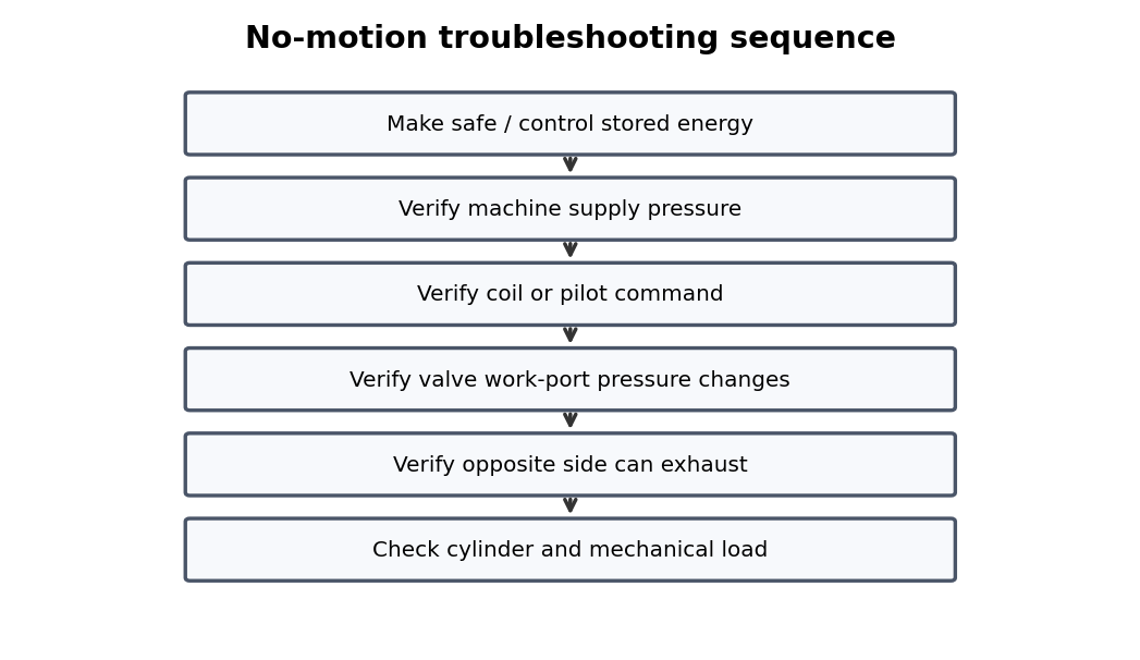
No extension can be caused by missing cap-end pressure, trapped rod-end pressure, internal leakage, or mechanical binding. Cylinder problems should be separated from valve and load problems by measuring both cylinder-port pressures while the fault is present.
What to check
- Measure working-side and opposing-side pressure.
- Inspect rod, mounts, alignment, guides, and load.
- Check flow controls and end cushions.
- Look for internal bypass or external seal leakage.
Diagnostic sequence
- Compare extension and retraction behavior.
- Measure both port pressures under load.
- If pressure conditions are wrong, move upstream to valve/exhaust.
- If pressure conditions are correct, inspect cylinder and machine mechanics.
Common mistakes
Increasing pressure to force through binding. • Ignoring rod-side effective area. • Replacing seals without correcting misalignment.
FIELD RULE: Use both port pressures to decide whether the problem is pneumatic or mechanical.
Cylinder Will Not Retract
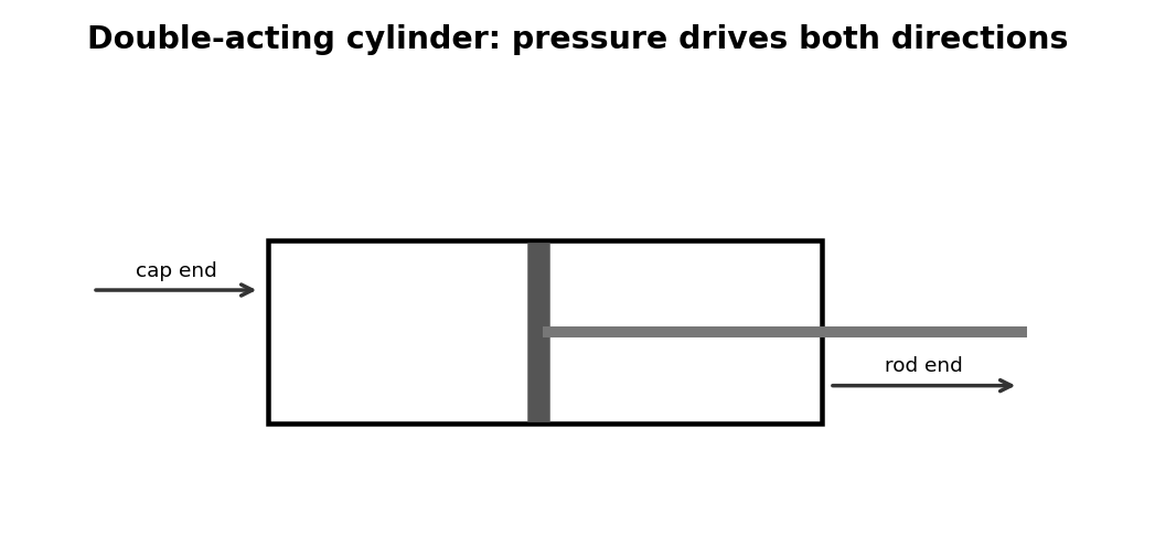
Retraction has lower effective area and may fail first when pressure margin is poor or cap-end exhaust is restricted. Cylinder problems should be separated from valve and load problems by measuring both cylinder-port pressures while the fault is present.
What to check
- Measure working-side and opposing-side pressure.
- Inspect rod, mounts, alignment, guides, and load.
- Check flow controls and end cushions.
- Look for internal bypass or external seal leakage.
Diagnostic sequence
- Compare extension and retraction behavior.
- Measure both port pressures under load.
- If pressure conditions are wrong, move upstream to valve/exhaust.
- If pressure conditions are correct, inspect cylinder and machine mechanics.
Common mistakes
Increasing pressure to force through binding. • Ignoring rod-side effective area. • Replacing seals without correcting misalignment.
FIELD RULE: Use both port pressures to decide whether the problem is pneumatic or mechanical.
Slow in One Direction
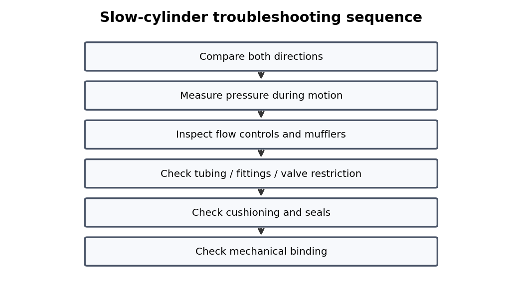
A one-direction speed problem usually points to a direction-specific valve passage, flow control, exhaust path, or mechanical load. Cylinder problems should be separated from valve and load problems by measuring both cylinder-port pressures while the fault is present.
What to check
- Measure working-side and opposing-side pressure.
- Inspect rod, mounts, alignment, guides, and load.
- Check flow controls and end cushions.
- Look for internal bypass or external seal leakage.
Diagnostic sequence
- Compare extension and retraction behavior.
- Measure both port pressures under load.
- If pressure conditions are wrong, move upstream to valve/exhaust.
- If pressure conditions are correct, inspect cylinder and machine mechanics.
Common mistakes
Increasing pressure to force through binding. • Ignoring rod-side effective area. • Replacing seals without correcting misalignment.
FIELD RULE: Use both port pressures to decide whether the problem is pneumatic or mechanical.
Slow in Both Directions
A both-directions speed problem points toward shared supply restriction, undersized tubing/valve, or mechanical friction. Cylinder problems should be separated from valve and load problems by measuring both cylinder-port pressures while the fault is present.
What to check
- Measure working-side and opposing-side pressure.
- Inspect rod, mounts, alignment, guides, and load.
- Check flow controls and end cushions.
- Look for internal bypass or external seal leakage.
Diagnostic sequence
- Compare extension and retraction behavior.
- Measure both port pressures under load.
- If pressure conditions are wrong, move upstream to valve/exhaust.
- If pressure conditions are correct, inspect cylinder and machine mechanics.
Common mistakes
Increasing pressure to force through binding. • Ignoring rod-side effective area. • Replacing seals without correcting misalignment.
FIELD RULE: Use both port pressures to decide whether the problem is pneumatic or mechanical.
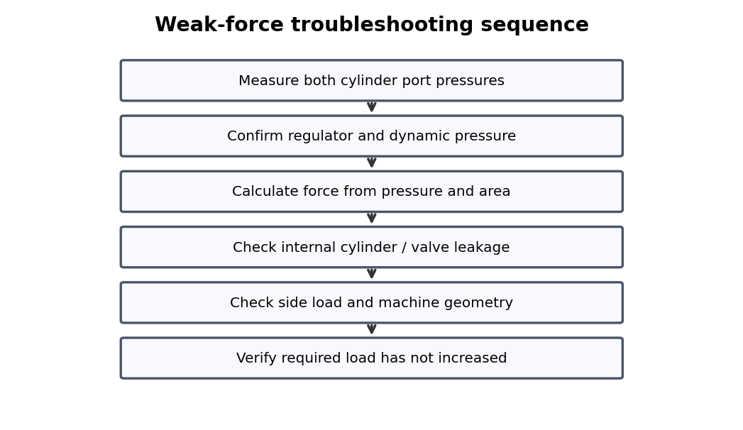
Weak Cylinder Force
Weak force requires both port pressures, cylinder area, and mechanical load to be evaluated together. Cylinder problems should be separated from valve and load problems by measuring both cylinder-port pressures while the fault is present.
What to check
- Measure working-side and opposing-side pressure.
- Inspect rod, mounts, alignment, guides, and load.
- Check flow controls and end cushions.
- Look for internal bypass or external seal leakage.
Diagnostic sequence
- Compare extension and retraction behavior.
- Measure both port pressures under load.
- If pressure conditions are wrong, move upstream to valve/exhaust.
- If pressure conditions are correct, inspect cylinder and machine mechanics.
Common mistakes
Increasing pressure to force through binding. • Ignoring rod-side effective area. • Replacing seals without correcting misalignment.
FIELD RULE: Use both port pressures to decide whether the problem is pneumatic or mechanical.
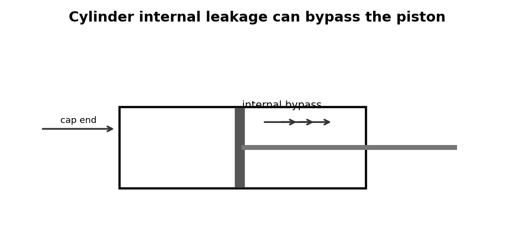
Piston Seal Bypass
Internal piston leakage can cause weak force, drift, or continuous exhaust without any external rod-seal leak. Cylinder problems should be separated from valve and load problems by measuring both cylinder-port pressures while the fault is present.
What to check
- Measure working-side and opposing-side pressure.
- Inspect rod, mounts, alignment, guides, and load.
- Check flow controls and end cushions.
- Look for internal bypass or external seal leakage.
Diagnostic sequence
- Compare extension and retraction behavior.
- Measure both port pressures under load.
- If pressure conditions are wrong, move upstream to valve/exhaust.
- If pressure conditions are correct, inspect cylinder and machine mechanics.
Common mistakes
Increasing pressure to force through binding. • Ignoring rod-side effective area. • Replacing seals without correcting misalignment.
FIELD RULE: Use both port pressures to decide whether the problem is pneumatic or mechanical.
Rod Seal Leakage
Rod-gland leakage is often accelerated by scratched rods, dirt, or side load rather than seal age alone. Cylinder problems should be separated from valve and load problems by measuring both cylinder-port pressures while the fault is present.
What to check
- Measure working-side and opposing-side pressure.
- Inspect rod, mounts, alignment, guides, and load.
- Check flow controls and end cushions.
- Look for internal bypass or external seal leakage.
Diagnostic sequence
- Compare extension and retraction behavior.
- Measure both port pressures under load.
- If pressure conditions are wrong, move upstream to valve/exhaust.
- If pressure conditions are correct, inspect cylinder and machine mechanics.
Common mistakes
Increasing pressure to force through binding. • Ignoring rod-side effective area. • Replacing seals without correcting misalignment.
FIELD RULE: Use both port pressures to decide whether the problem is pneumatic or mechanical.
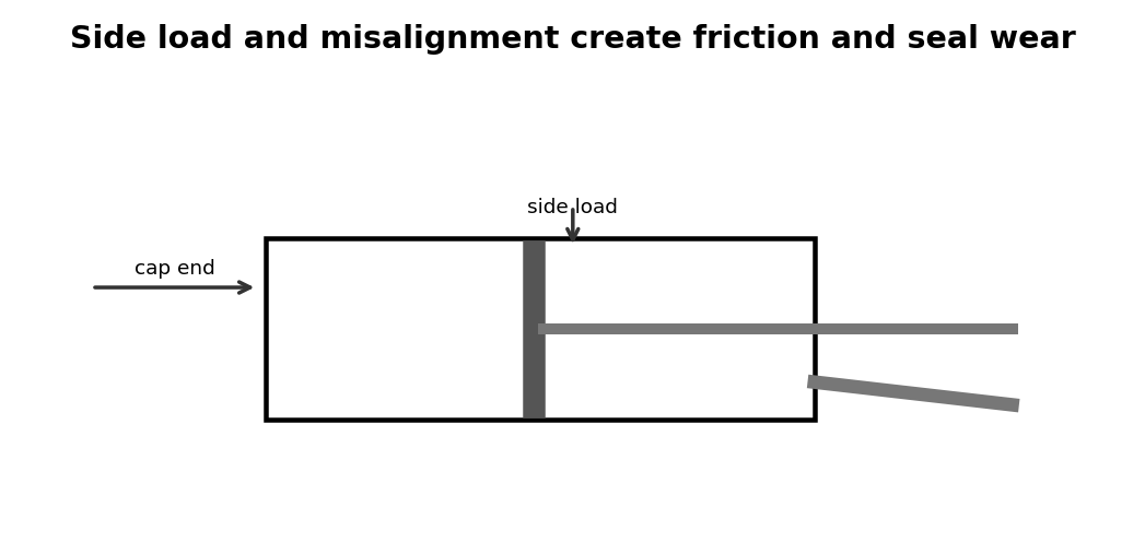
Bent Rods
A bent rod can make pressure rise normally while motion stalls at repeatable positions. Cylinder problems should be separated from valve and load problems by measuring both cylinder-port pressures while the fault is present.
What to check
- Measure working-side and opposing-side pressure.
- Inspect rod, mounts, alignment, guides, and load.
- Check flow controls and end cushions.
- Look for internal bypass or external seal leakage.
Diagnostic sequence
- Compare extension and retraction behavior.
- Measure both port pressures under load.
- If pressure conditions are wrong, move upstream to valve/exhaust.
- If pressure conditions are correct, inspect cylinder and machine mechanics.
Common mistakes
Increasing pressure to force through binding. • Ignoring rod-side effective area. • Replacing seals without correcting misalignment.
FIELD RULE: Use both port pressures to decide whether the problem is pneumatic or mechanical.
Mounting Misalignment
Misaligned mounts and worn pivots create side load, seal wear, and repeat cylinder failures. Cylinder problems should be separated from valve and load problems by measuring both cylinder-port pressures while the fault is present.
What to check
- Measure working-side and opposing-side pressure.
- Inspect rod, mounts, alignment, guides, and load.
- Check flow controls and end cushions.
- Look for internal bypass or external seal leakage.
Diagnostic sequence
- Compare extension and retraction behavior.
- Measure both port pressures under load.
- If pressure conditions are wrong, move upstream to valve/exhaust.
- If pressure conditions are correct, inspect cylinder and machine mechanics.
Common mistakes
Increasing pressure to force through binding. • Ignoring rod-side effective area. • Replacing seals without correcting misalignment.
FIELD RULE: Use both port pressures to decide whether the problem is pneumatic or mechanical.
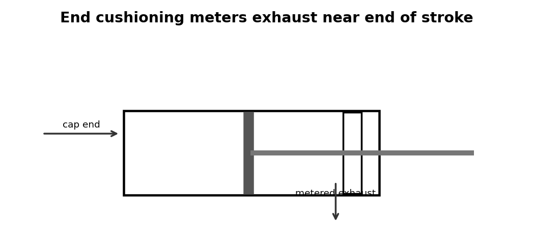
End-of-Stroke Cushioning
Too little cushioning causes impact while too much can prevent the piston from reaching its end sensor quickly. Cylinder problems should be separated from valve and load problems by measuring both cylinder-port pressures while the fault is present.
What to check
- Measure working-side and opposing-side pressure.
- Inspect rod, mounts, alignment, guides, and load.
- Check flow controls and end cushions.
- Look for internal bypass or external seal leakage.
Diagnostic sequence
- Compare extension and retraction behavior.
- Measure both port pressures under load.
- If pressure conditions are wrong, move upstream to valve/exhaust.
- If pressure conditions are correct, inspect cylinder and machine mechanics.
Common mistakes
Increasing pressure to force through binding. • Ignoring rod-side effective area. • Replacing seals without correcting misalignment.
FIELD RULE: Use both port pressures to decide whether the problem is pneumatic or mechanical.
Cylinder Drift
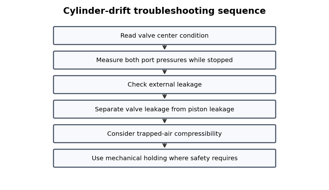
Drift can originate in the cylinder, valve, center condition, external leakage, or compressibility of trapped air. Cylinder problems should be separated from valve and load problems by measuring both cylinder-port pressures while the fault is present.
What to check
- Measure working-side and opposing-side pressure.
- Inspect rod, mounts, alignment, guides, and load.
- Check flow controls and end cushions.
- Look for internal bypass or external seal leakage.
Diagnostic sequence
- Compare extension and retraction behavior.
- Measure both port pressures under load.
- If pressure conditions are wrong, move upstream to valve/exhaust.
- If pressure conditions are correct, inspect cylinder and machine mechanics.
Common mistakes
Increasing pressure to force through binding. • Ignoring rod-side effective area. • Replacing seals without correcting misalignment.
FIELD RULE: Use both port pressures to decide whether the problem is pneumatic or mechanical.
Cylinder Position Sensors
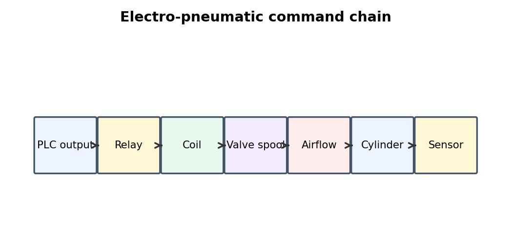
A reed or solid-state sensor can indicate piston position without proving the actuator developed enough force to complete the mechanism. Electro-pneumatic faults cross the boundary between PLC logic and air power, so the command must be traced from the controller all the way to physical motion and back to sensor feedback.
What to check
- Monitor PLC output and actual field voltage.
- Measure coil voltage with the coil connected.
- Check relay/connector voltage drop.
- Verify valve work-port pressure changes and final sensor state.
Diagnostic sequence
- Start at the PLC or relay command.
- Move one stage toward the actuator until expected behavior disappears.
- Repair that stage.
- Verify final pneumatic motion and sensor feedback through repeated cycles.
Common mistakes
Assuming PLC bit ON means the coil is powered. • Assuming relay LED means the contact is good. • Changing PLC logic before proving hardware.
FIELD RULE: Trace the command chain one link at a time.
Rodless Cylinders and Slides
Guided and rodless actuators add carriage bearings, seal strips, and load moments to the troubleshooting picture. Cylinder problems should be separated from valve and load problems by measuring both cylinder-port pressures while the fault is present.
What to check
- Measure working-side and opposing-side pressure.
- Inspect rod, mounts, alignment, guides, and load.
- Check flow controls and end cushions.
- Look for internal bypass or external seal leakage.
Diagnostic sequence
- Compare extension and retraction behavior.
- Measure both port pressures under load.
- If pressure conditions are wrong, move upstream to valve/exhaust.
- If pressure conditions are correct, inspect cylinder and machine mechanics.
Common mistakes
Increasing pressure to force through binding. • Ignoring rod-side effective area. • Replacing seals without correcting misalignment.
FIELD RULE: Use both port pressures to decide whether the problem is pneumatic or mechanical.
Rotary Actuators and Air Motors
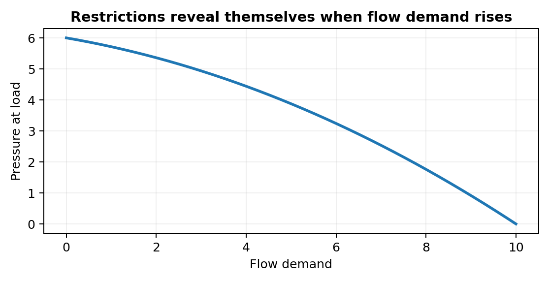
Rotary pneumatic devices require sustained flow as well as pressure, especially at speed. Cylinder problems should be separated from valve and load problems by measuring both cylinder-port pressures while the fault is present.
What to check
- Measure working-side and opposing-side pressure.
- Inspect rod, mounts, alignment, guides, and load.
- Check flow controls and end cushions.
- Look for internal bypass or external seal leakage.
Diagnostic sequence
- Compare extension and retraction behavior.
- Measure both port pressures under load.
- If pressure conditions are wrong, move upstream to valve/exhaust.
- If pressure conditions are correct, inspect cylinder and machine mechanics.
Common mistakes
Increasing pressure to force through binding. • Ignoring rod-side effective area. • Replacing seals without correcting misalignment.
FIELD RULE: Use both port pressures to decide whether the problem is pneumatic or mechanical.
Appendix C – Slow-Cylinder Checklist
- Compare both directions.
- Measure pressure during motion.
- Check flow controls and mufflers.
- Check tubing/fittings and valve flow path.
- Check cushioning.
- Check seals, alignment, and load friction.
USE IT: Add machine-specific target pressures, cycle times, and test points to this page.
Continue the series
- Previous chapter: Pneumatic Directional Valves
- Next chapter: Pneumatic Tubing, Fittings, And Exhaust
- Browse all Pneumatic Troubleshooting chapters
Adapted from Pneumatic Troubleshooting for Maintenance Technicians, by Dovydas Kersys. © 2026 Dovydas Kersys. Featured cover image is an AI-generated editorial illustration.