Single-Turn Absolute Encoders
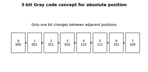
A single-turn absolute encoder assigns a unique code to each angular position within one revolution. After power-up, the controller can read the shaft angle without counting from a reference point, provided the communication link and configuration are correct.
What to Check
- Check resolution in bits or counts/revolution.
- Compare raw value while rotating slowly through one turn.
- Verify rollover at the 0/maximum boundary.
Diagnostic Sequence
- Look for missing codes, jumps, or reversed direction.
- Check electronic preset/zero settings.
- Verify that the receiving device interprets binary or Gray conversion correctly if applicable.
Common Mistakes
- Expecting single-turn data to remember number of revolutions.
- Using the wrong bit length.
- Treating a rollover at one revolution as a fault.
Field Rule: Know whether the application needs angle within one turn or total multiturn position.
Multiturn Absolute Encoders
Multiturn encoders add revolution count to the single-turn position. Multiturn information may be stored mechanically, magnetically, electronically, or with energy-harvesting methods depending on design. Replacement must match both single-turn and multiturn range.
What to Check
- Record raw single-turn and multiturn values if available.
- Check behavior through several revolutions.
- Verify battery or energy-storage requirements on applicable models.
Diagnostic Sequence
- Rotate across a revolution boundary and confirm multiturn increments correctly.
- Power-cycle and confirm retained position.
- Check preset and direction parameters after replacement.
Common Mistakes
- Replacing with correct connector but smaller multiturn range.
- Assuming all multiturn encoders need batteries.
- Resetting position before recording the failed unit’s configuration.
Field Rule: Capture configuration and raw position before removing a smart absolute encoder.
Gray Code Outputs
Parallel absolute encoders may use Gray code because adjacent positions change only one bit, reducing ambiguity during transitions. The controller must either decode Gray to binary or receive already-decoded data.
What to Check
- Identify whether outputs are Gray or binary.
- Check bit order and active polarity.
- Inspect each bit for stuck high/low behavior.
Diagnostic Sequence
- Rotate one step at a time and compare code sequence.
- A single failed bit creates predictable position patterns.
- Verify software conversion with a known code table.
Common Mistakes
- Reading Gray code directly as binary.
- Reversing bit significance.
- Assuming multiple changing bits always mean noise when the code is binary.
Field Rule: Code format is part of the electrical interface.
SSI Interface Basics
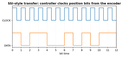
Synchronous Serial Interface (SSI) uses a controller-generated clock and encoder-returned data. Troubleshooting therefore includes both directions: the controller must generate valid clock pulses, and the encoder must return data with correct timing and level.
What to Check
- Confirm clock and data pairs, polarity, and differential standard.
- Check configured bit length and clock rate.
- Check whether parity, status, or extra bits are expected.
Diagnostic Sequence
- Scope clock and data together at the receiver.
- Verify the encoder receives its supply before clock activity begins.
- Reduce clock rate if allowed to test a marginal cable.
Common Mistakes
- Looking only at data and ignoring missing clock.
- Using the wrong bit length and interpreting shifted positions.
- Measuring differential clock/data as ordinary single-ended signals.
Field Rule: Serial absolute feedback is a conversation: verify both the request and the response.
BiSS-Style High-Speed Serial Feedback
BiSS and similar synchronous encoder interfaces can carry high-resolution position and status information at higher rates. Exact frame structure varies by implementation, so troubleshooting should use the encoder and controller documentation rather than assumptions.
What to Check
- Record configured interface variant, clock, frame length, and error/status bits.
- Check differential wiring and termination.
- Inspect error counters in the controller.
Diagnostic Sequence
- Use controller diagnostics before attempting protocol decoding.
- Capture physical-layer waveforms if error counters rise.
- Compare a known-good cable or axis when available.
Common Mistakes
- Guessing frame format from another encoder model.
- Ignoring CRC/status faults while position still appears plausible.
- Swapping cable without matching impedance and pair layout.
Field Rule: For smart feedback, controller diagnostics and physical-layer quality are equally important.
Preset, Zero, and Electronic Offset
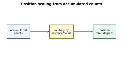
Absolute encoders often support an electronic preset that makes the current mechanical position correspond to a chosen raw value. A replacement can be electrically perfect but make the machine “wrong” because its zero or direction differs.
What to Check
- Save preset, offset, direction, and scaling parameters before replacement.
- Mark mechanical position before removal.
- Confirm whether zero is stored in encoder or controller.
Diagnostic Sequence
- After replacement, verify raw position before enabling automatic motion.
- Set preset using the approved commissioning procedure.
- Check software limits after zeroing.
Common Mistakes
- Rotating the coupling randomly before setting zero.
- Assuming factory zero matches machine zero.
- Forgetting that a controller may also apply an additional offset.
Field Rule: Mechanical zero, encoder zero, and software zero are three different things.
Serial Encoder Error Bits
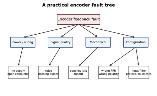
Smart encoders may report warnings for low signal amplitude, temperature, overspeed, internal memory, CRC, magnet quality, or position validity. These bits are often more useful than a generic “encoder fault” alarm.
What to Check
- Read the exact diagnostic/status word.
- Record active and historical error bits.
- Check whether warning and fault levels are distinct.
Diagnostic Sequence
- Correlate error bits with temperature, speed, and machine state.
- Clear history only after recording it.
- Use manufacturer diagnostic software when available.
Common Mistakes
- Ignoring warnings because the axis still moves.
- Replacing hardware without recording the status word.
- Treating a communication error as mechanical position error.
Field Rule: Smart feedback tells you more than position – use its diagnostic data.
Replacing Absolute Encoders Safely
Absolute encoder replacement can change machine position immediately. Incorrect zero, direction, resolution, or multiturn value can command unexpected motion if the controller trusts the new feedback.
What to Check
- Secure the axis and follow lockout procedures.
- Record old raw position and configuration when possible.
- Match exact electrical and mechanical specifications.
Diagnostic Sequence
- Install and verify raw feedback in a safe maintenance state.
- Check direction with a small controlled movement.
- Re-establish home/preset and software limits before automatic operation.
Common Mistakes
- Powering directly into automatic mode.
- Assuming connector compatibility equals protocol compatibility.
- Skipping limit checks after preset.
Field Rule: Treat absolute encoder replacement as a commissioning task, not just a parts swap.