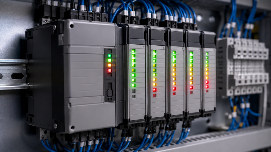
A red LED on an Allen-Bradley I/O module does not automatically mean the module is dead.
It might indicate a lost controller connection, missing field power, shorted output, incorrect configuration, firmware update, chassis-size mismatch—or, yes, an internal module failure.
The colour alone is not enough. You must also check:
- Which LED is illuminated
- Whether it is steady or flashing
- The exact module catalog number
- Whether you are looking at an adapter, an I/O module or an individual channel
A flashing red NET indicator means something entirely different from a flashing red POINTBus indicator. They may be only a few centimetres apart, which is rather convenient when you are trying to diagnose a stopped machine under pressure.
Safety warning: Status LEDs are diagnostic aids, not proof that a circuit is electrically safe. Isolate and verify hazardous energy before touching wiring or removing modules.
Quick Allen-Bradley LED Colour Guide
This table is a useful starting point, but exact meanings vary between module families.
| LED state | Common meaning |
|---|---|
| Off | No power, inactive point or unconfigured function |
| Steady green | Normal operation with an active connection |
| Flashing green | Powered and healthy, but no active connection or not currently controlled |
| Steady yellow | Input or output point is on |
| Flashing red | Recoverable fault, communication timeout or field-side problem |
| Steady red | Serious or nonrecoverable module fault |
| Flashing red/green | Self-test, safety commissioning or another special state |
Do not replace a module based only on this general table. Always identify the LED label and consult the exact module documentation.
Start by Reading the LED Label
Allen-Bradley I/O systems use several different indicator labels.
OK or MOD
This normally reports the health of the module and its connection to the owning controller.
NET or NS
This reports the device’s EtherNet/IP network condition, including whether it has an IP address and whether CIP connections are established.
LINK, LINK1 or LINK2
These indicators report the physical Ethernet link and network activity on a port.
ST, IN or OUT
These show the state of an individual input or output channel.
FLT
This indicates a channel or group fault, such as an open wire or output problem.
FUSE
Found on certain electronically fused output modules. It indicates that the module detected a short-circuit or overload condition.
POINTBus
Found on POINT I/O adapters. It indicates the condition of the POINTBus connection between the adapter and its attached I/O modules.
SA, System Power or Field Power
These indicate whether module or field-side power is present.
The fastest way to create confusion is to call every red indicator “the module fault light.” They are not interchangeable.
ControlLogix 1756 I/O LEDs
Standard ControlLogix digital I/O modules commonly use an OK indicator for module and communication status.
ControlLogix input-module OK indicator
| OK indicator | Meaning |
|---|---|
| Steady green | Inputs are being multicast and the module is operating normally |
| Flashing green | Internal diagnostics passed, but the module is not multicasting data or is inhibited |
| Flashing red | A previously established communication connection timed out |
| Steady red | The module has a serious fault and should be replaced |
For a flashing green input module, check whether the module is inhibited, whether an owner-controller connection exists and whether the I/O configuration matches the installed hardware.
For flashing red, investigate the controller, chassis and communication path rather than immediately replacing the module.
ControlLogix output-module OK indicator
| OK indicator | Meaning |
|---|---|
| Steady green | Outputs are actively controlled by a controller |
| Flashing green | Module diagnostics passed, but outputs are not actively controlled |
| Flashing red | A previously established connection timed out |
| Steady red | The module must be replaced |
A ControlLogix output module can flash green when it is inhibited, has no active connection or when the controller is in Program mode. The module may therefore be healthy even though it is not controlling its outputs.
Yellow channel LEDs
A yellow ST or channel indicator means the corresponding input or output point is on.
For an input module, it means the module detects the field input as active.
For an output module, it means the output point is commanded on. It does not, by itself, prove that voltage reaches the load or that the solenoid, contactor or valve actually operates. That conclusion still requires electrical testing.
Red FLT and FUSE indicators
Diagnostic ControlLogix modules may provide red fault indicators for individual points.
A red FLT indicator means the corresponding point has reported a fault. Depending on the module, this may involve an open wire, field-power problem or another channel diagnostic.
A red FUSE indicator on an electronically fused output module points toward a short-circuit or overload condition. Rockwell recommends checking the field wiring and reviewing the module properties in Studio 5000 before resetting the electronic fuse.
Compact 5000 I/O: 5069 Module LEDs
Compact 5000 modules generally use a MOD indicator.
5069 MOD indicator
| MOD indicator | Meaning |
|---|---|
| Off | Module power is missing or the module is not installed correctly |
| Steady green | Connected to its owner-controller and operating normally |
| Flashing green | Powered, but no valid owner-controller connection exists |
| Flashing red | Recoverable fault, firmware activity or connection timeout |
| Steady red | Nonrecoverable module fault |
| Flashing red/green | On safety modules, the required UNID has not been commissioned |
A flashing green MOD light commonly appears when the module configuration is missing, incomplete or incorrect. It can also occur when the module is inhibited.
A flashing red MOD indicator needs more investigation. Possible causes include:
- A firmware update in progress
- A failed firmware update
- A recoverable module fault
- A timed-out controller connection
Open the module properties in Studio 5000 and inspect the Connection and Module Info pages. If the fault is recoverable, the module may be reset from the Module Info page or by cycling power after correcting the cause.
A steady red MOD light indicates a nonrecoverable condition. Rockwell recommends cycling power once and replacing the module if steady red remains.
Compact 5000 Channel LEDs
For standard digital 5069 modules:
| Channel indicator | Typical meaning |
|---|---|
| Off | Point is off or module power is unavailable |
| Steady yellow | Point is on |
| Flashing red | A point-level fault has been detected |
The meaning of flashing red depends on the module.
On an input module, it can indicate field-power loss.
On a DC output module, it may indicate:
- No-load condition
- Short circuit
- Field-power loss
On relay and AC output modules, flashing red can also report missing field power. Safety I/O modules have additional patterns for overloads, shorts to ground and internal hardware faults.
This is why the catalog number matters. A flashing red channel on a 5069-IB16F input module does not necessarily mean the same thing as flashing red on a 5069-OB16F output module.
POINT I/O Adapter LEDs
A POINT I/O system can have several healthy I/O modules but still fail because the 1734 EtherNet/IP adapter has a network or POINTBus problem.
The adapter normally contains indicators for:
- Module Status
- Network Activity
- Network Status
- POINTBus Status
- System Power
- Field Power
Module Status
| Indicator | Meaning |
|---|---|
| Off | No adapter power |
| Flashing green | Missing, incomplete or incorrect configuration |
| Solid green | Adapter operating normally |
| Flashing red | Recoverable fault |
| Solid red | Unrecoverable fault |
A flashing red Module Status indicator can be associated with firmware or address-switch conditions. A solid red indicator can point to a self-test or fatal firmware failure.
Network Status
| Indicator | Meaning |
|---|---|
| Off | Adapter is not initialized or has no IP address |
| Flashing green | IP address exists, but no CIP connections are established |
| Solid green | CIP connections are established |
| Flashing red | One or more CIP connections have timed out |
| Solid red | Duplicate IP address |
| Flashing red/green | Adapter is performing a power-up self-test |
A solid red Network Status light is one of the clearer diagnoses: another device is using the same IP address.
A flashing green Network Status light is not necessarily a fault. It means the adapter is configured on the network but does not currently have an active CIP connection.
POINTBus Status
| Indicator | Meaning |
|---|---|
| Off | Adapter or POINTBus is not powered |
| Solid green | Adapter and attached modules are operating normally |
| Flashing green | Firmware update is in progress |
| Flashing red | Recoverable POINTBus fault |
| Solid red | Unrecoverable bus-off condition |
| Flashing red/green | Power-up test |
A flashing red POINTBus indicator commonly appears when:
- The configured chassis size does not match the physical system
- An expected module is missing
- An I/O connection has timed out
- A module was removed from an active system
For POINT I/O, the chassis size includes the adapter itself. One adapter plus ten I/O modules requires a chassis-size value of eleven. A wrong value can prevent I/O connections even when every module is installed and powered.
System Power and Field Power
| Indicator | Meaning |
|---|---|
| System Power green | Internal 5 V system supply is operating |
| Field Power green | 24 V DC field power is present |
| Either indicator off | The corresponding supply is missing or has a problem |
This helps separate adapter-electronics power from the supply used by field devices.
You may therefore see a healthy adapter and normal network connection while the Field Power indicator remains off. In that condition, the network can communicate perfectly while sensors and outputs remain dead.
FLEX 5000 I/O LEDs
FLEX 5000 standard and safety I/O modules follow a pattern similar to Compact 5000 modules.
A steady green module indicator normally means the module has an owner-controller connection and is operating normally. Flashing green means the module is healthy but does not currently have the required connection or is in an idle state.
Flashing red can indicate:
- Firmware activity
- Recoverable module fault
- Connection timeout
Steady red indicates a nonrecoverable fault. Safety modules may use alternating red and green to indicate that safety identity commissioning is required.
Individual FLEX 5000 channel indicators vary according to whether the module is digital, analog, safety or relay output. Use the exact 5094 catalog-number manual rather than assuming every red channel LED means a short circuit.
Analog I/O Indicators
Analog modules often provide fewer point-state LEDs than digital modules because an analog channel does not have a simple on/off state.
For standard ControlLogix analog I/O modules:
| OK indicator | Meaning |
|---|---|
| Steady green | Module is operating normally |
| Flashing green | Diagnostics passed, but connected communication is not active |
| Flashing red | A previously established connection timed out |
| Steady red | The module has a major fault |
Some analog modules also have a flashing calibration indicator while calibration is in progress. HART analog modules may provide per-channel fault indicators for conditions such as underrange, overrange and wire-off detection.
Do not expect an analog channel LED to tell you whether the transmitter is producing the correct engineering value. Confirm the raw input, channel diagnostics and scaling inside Studio 5000.
The LED Is Yellow, but the Device Does Not Work
This is a very common maintenance situation.
Suppose the yellow LED for an output point is on, yet the contactor does not pull in.
The illuminated LED suggests that the module considers the output active. It does not prove that:
- Field power is available
- The output terminal has the expected voltage
- The wire is intact
- The load has a valid return path
- The contactor coil is healthy
- An interposing relay has switched correctly
Measure the output terminal relative to the correct common. Then follow the circuit through terminal blocks, fuses, relays and the connected load.
The LED is a clue. Not a complete electrical test.
The Input LED Is On, but the PLC Tag Is Off
When the input LED is on but the controller does not see the input, check the module-level connection first.
Possible causes include:
- Module inhibited in Studio 5000
- Missing owner connection
- Incorrect module definition
- Electronic-keying mismatch
- Communication timeout
- Wrong slot selected in the program
- Logic referencing a different input tag
A point LED can report the local electrical state even while the module’s connection to the controller is unhealthy.
Look at the module in the Studio 5000 I/O Configuration tree. A yellow warning icon normally indicates a connection or configuration problem. ControlLogix documentation recommends checking the Connection tab and Module Info information rather than relying only on the front indicators.
A Practical LED Troubleshooting Sequence
1. Record the exact pattern
Write down or photograph:
Module catalog number
LED label
Colour
Steady or flashing
Other LEDs illuminated at the same time
Machine condition when the fault appeared
“Red light on remote I/O” is not enough information.
2. Check module and field power
An adapter can have system power but no field power. Likewise, an individual channel LED may remain off simply because the field supply is missing.
3. Check the module-status indicator
Determine whether the module is healthy, disconnected, recoverably faulted or nonrecoverably faulted.
4. Check the adapter and network
For remote I/O, examine NET, LINK and bus-status indicators before blaming an individual I/O card.
5. Check individual channels
A red channel indicator points you toward wiring, field power, an open load or a short, depending on the module.
6. Open Studio 5000
Check:
I/O Configuration
Module Properties
Connection
Module Info
Module Diagnostics
Controller Tags
The software normally provides a fault code or description that is more specific than the LED.
7. Correct the cause before resetting
Resetting a module will not repair a damaged cable, restore missing 24 V DC or correct the wrong chassis size.
Final Thoughts
Allen-Bradley status LEDs become much easier to understand once you separate them into three levels:
Adapter or network status
        ↓
Module and controller-connection status
        ↓
Individual I/O channel status
Green normally means healthy—but flashing green may mean no connection.
Yellow normally means a point is on—but not necessarily that the field device operates.
Flashing red often means something recoverable.
Steady red is the one to take seriously, although even then the recommended action depends on the module family and exact indicator.
Read the label. Record the pattern. Check Studio 5000. Then reach for the multimeter.
Not the spare module.