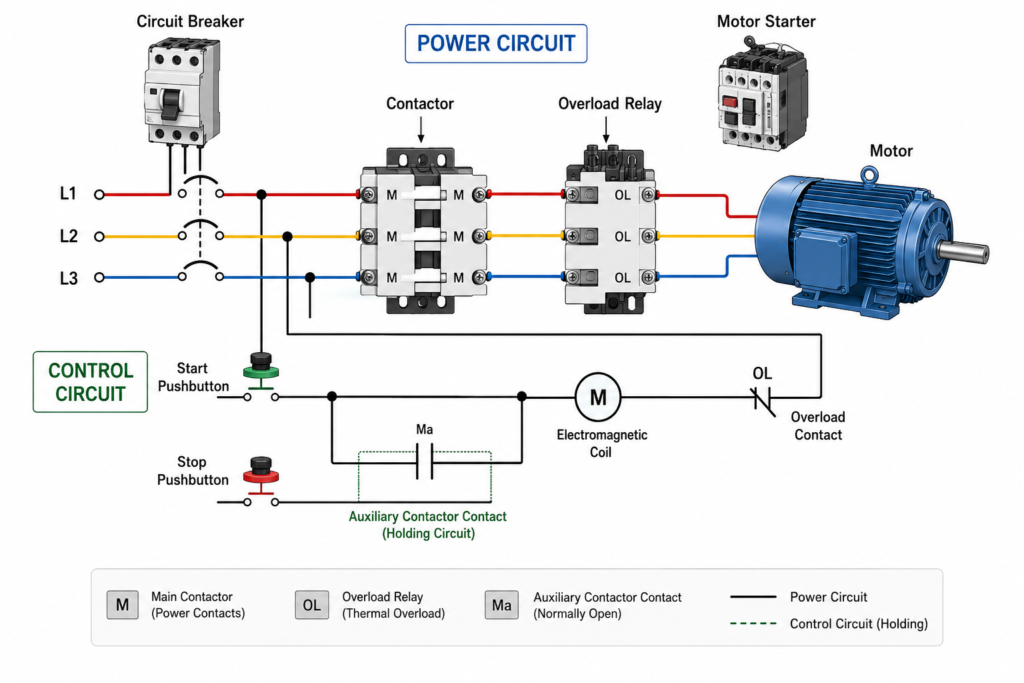
Electric motors must be controlled before they can perform useful work safely.
At the most basic level, motor control means starting and stopping the motor. In industrial systems, however, the control circuit must also protect the motor and its supply wiring from electrical and mechanical problems.
A common motor-control circuit uses:
- A contactor
- An overload relay
- A circuit breaker or fuses
- Start and stop pushbuttons
- Auxiliary contacts
- Other control devices when required
Together, these components allow an operator or automation system to start the motor, stop it and protect it when abnormal conditions occur.
What Is a Motor Starter?
A motor starter is generally made from two main components:
Contactor
+
Overload relay
=
Motor starter
The contactor switches power to the motor.
The overload relay monitors motor current and trips when the motor remains overloaded for too long.
A starter therefore performs two essential jobs:
- It controls whether the motor runs.
- It protects the motor from sustained overload current.
A motor starter does not normally provide complete short-circuit protection by itself. Fuses or a circuit breaker are also required.
How a Contactor Starts the Motor
A contactor is an electrically operated switch designed to control loads such as three-phase motors.
Its main contacts are installed in the motor power circuit.
When the contactor coil is energized, the main contacts close and connect the motor to the electrical supply.
Contactor coil energized
↓
Main contacts close
↓
Power reaches the motor
↓
Motor starts
When the coil is de-energized:
Contactor coil de-energized
↓
Main contacts open
↓
Motor supply is disconnected
↓
Motor stops
The contactor allows a relatively small control signal to switch a much larger motor current.
Start and Stop Pushbutton Operation
A basic control circuit normally uses:
- A normally open START pushbutton
- A normally closed STOP pushbutton
- A contactor coil
- A normally open contactor auxiliary contact
When the operator presses START, current flows through the control circuit and energizes the contactor coil.
The contactor closes its main power contacts and starts the motor.
At the same time, a normally open auxiliary contact closes and creates a holding circuit around the START pushbutton.
START pressed
↓
Contactor coil energizes
↓
Auxiliary contact closes
↓
Coil remains energized after START is released
This is commonly called a seal-in or holding circuit.
The motor continues running until the control circuit is interrupted.
How the Stop Button Works
The STOP pushbutton is normally closed and wired in series with the contactor coil.
Pressing STOP opens the control circuit.
The contactor coil loses power, causing the main contacts and holding contact to open.
The motor then stops.
A normally closed STOP circuit is commonly used because a broken wire or loss of control power also causes the contactor to release rather than remain energized.
The Purpose of the Overload Relay
A motor may draw excessive current when:
- A conveyor becomes jammed
- A pump is mechanically blocked
- A bearing begins to seize
- The motor is overloaded
- One supply phase is lost
- Voltage becomes unbalanced
- The motor starts too frequently
The overload relay detects sustained overcurrent and opens its normally closed control contact.
This removes power from the contactor coil.
Motor overload occurs
↓
Overload relay trips
↓
Overload control contact opens
↓
Contactor drops out
↓
Motor is disconnected
The overload relay protects the motor from overheating caused by excessive current over time.
It does not normally interrupt high short-circuit current directly. Instead, it causes the contactor to open during an overload condition.
Overload Protection Is Not Short-Circuit Protection
An overload and a short circuit are not the same fault.
Motor overload
An overload usually produces current above the motor’s rated operating value, but the current may still be relatively limited.
It can continue for several seconds or minutes and gradually overheat the motor.
Short circuit
A short circuit can produce extremely high current almost instantly.
It may result from:
- Damaged cable insulation
- Phase-to-phase contact
- Phase-to-earth contact
- Internal motor winding failure
- Incorrect wiring
Short-circuit current must be interrupted quickly by a suitable protective device.
This is why a motor branch circuit normally includes:
Circuit breaker or fuses
+
Contactor
+
Overload relay
Each component performs a different function.
Responsibilities of the Main Components
| Component | Main purpose |
|---|---|
| Circuit breaker or fuses | Short-circuit and branch-circuit protection |
| Contactor | Starts and stops the motor |
| Overload relay | Protects the motor against sustained overload |
| Start pushbutton | Requests the motor to run |
| Stop pushbutton | Interrupts the run command |
| Auxiliary contact | Holds the contactor energized |
| Disconnecting device | Provides a means to isolate the circuit |
The exact equipment required depends on the installation, motor rating and applicable electrical rules.
What Is a Combination Starter?
A combination starter groups the main motor-control and protection components into one assembly.
It commonly includes:
- Disconnecting means
- Short-circuit protective device
- Contactor
- Motor overload protection
The components may be installed inside one enclosure or assembled as part of an MCC unit.
A combination starter gives the motor circuit a complete control and protection arrangement rather than using a contactor and overload relay alone.
One Starter Normally Controls One Motor
In a conventional arrangement, one motor starter controls one motor.
This makes it possible to:
- Select protection for the individual motor
- Isolate one motor without stopping every machine
- Diagnose faults more easily
- Provide separate operating controls
- Apply the correct overload setting
For a small installation with only a few motors, the starter may be installed in a local panel near the equipment.
Examples include:
- A small pump station
- A standalone conveyor
- A ventilation fan
- A workshop machine
- A local compressor
Local installation can simplify wiring when motors are spread across a large area.
What Is a Motor Control Center?
A motor control center, usually abbreviated as MCC, is a centralized assembly containing multiple motor-control units.
An MCC is essentially a physical grouping of combination starters and related control equipment.
It may control:
- Pumps
- Conveyors
- Fans
- Compressors
- Mixers
- Process equipment
- Heating and ventilation motors
Instead of installing many separate starter panels around the plant, the motor circuits are organized inside one structured assembly.
Typical MCC Components
An MCC may contain:
- Main incoming disconnect
- Busbars
- Circuit breakers or fused switches
- Contactors
- Overload relays
- Variable-frequency drives
- Soft starters
- Control transformers
- Relays
- PLC remote I/O
- Communication modules
- Metering equipment
Each motor feeder is normally installed in its own compartment or functional unit.
Depending on the MCC design, the units may be fixed or withdrawable.
Advantages of an MCC
A motor control center can provide:
- Centralized motor control
- Organized power distribution
- Easier maintenance
- Improved fault isolation
- Reduced field-panel requirements
- Standardized motor feeders
- Space-efficient installation
- Easier expansion
Maintenance personnel can inspect and service multiple motor circuits from one location.
Centralized control also makes it easier to integrate the motors with a PLC, HMI or plant supervisory system.
Local and Remote Motor Control
A motor may be controlled locally, remotely or through both methods.
Local control
The operator uses pushbuttons located near the motor.
This is useful during:
- Maintenance
- Commissioning
- Cleaning
- Equipment testing
Remote control
The motor receives commands from:
- PLC outputs
- HMI controls
- Process controllers
- Level switches
- Pressure switches
- Automatic sequence logic
Many industrial systems use a LOCAL–OFF–REMOTE selector switch.
In LOCAL mode, nearby pushbuttons control the motor.
In REMOTE mode, the PLC or process system controls it.
The logic must ensure that only the intended control source can command the motor.
Basic PLC Motor Control
When a PLC controls the starter, the physical contactor and overload relay are still required unless another device performs those functions.
A typical signal path is:
HMI or automatic start request
↓
PLC checks permissives
↓
PLC output energizes contactor coil
↓
Contactor starts motor
↓
Auxiliary feedback confirms operation
The PLC may monitor:
- Contactor feedback
- Overload status
- Motor protection status
- Drive-ready signal
- Running feedback
- Local or remote selection
The PLC should distinguish between the command and the physical response.
For example:
Motor_Start_Command = TRUE
Contactor_Feedback = FALSE
This condition may indicate:
- Failed contactor coil
- Missing control voltage
- Open overload contact
- Wiring fault
- Defective PLC output
- Mechanically stuck contactor
Motor Starting Permissives
Automatic systems normally require several conditions before the motor can start.
These may include:
- Overload relay healthy
- Emergency-stop system healthy
- Guard conditions satisfied
- Required valve open
- Lubrication available
- Downstream equipment ready
- Correct operating mode selected
- No active motor fault
A simplified command may be:
Motor_Run_Command :=
    Start_Request
    AND Motor_Permissive
    AND NOT Stop_Request
    AND NOT Motor_Fault;
Safety-related functions must be implemented using the required safety-rated architecture. Ordinary PLC logic does not replace safety relays, safety PLCs or safe drive functions where they are required.
Direct-On-Line Starting
The basic contactor starter is often called a direct-on-line or across-the-line starter.
When the contactor closes, full supply voltage is applied to the motor.
This provides:
- Simple operation
- High starting torque
- Low equipment complexity
It also creates high starting current.
Direct-on-line starting is commonly used where:
- The electrical supply can handle the inrush current
- Mechanical equipment can tolerate abrupt acceleration
- Variable speed is not needed
- The motor size is suitable for the installation
Larger motors or sensitive mechanical systems may require another starting method.
Other Motor-Control Methods
More advanced motor-control equipment includes:
Reversing starters
Two contactors change the phase sequence and reverse motor direction.
Electrical and mechanical interlocking prevents both contactors from closing simultaneously.
Star-delta starters
The motor initially starts with its windings connected in star and later changes to delta.
This can reduce starting current, although it also reduces starting torque.
Soft starters
A soft starter gradually increases the voltage applied to the motor.
It reduces mechanical shock and electrical starting current.
Variable-frequency drives
A VFD controls motor speed by changing the frequency and voltage supplied to the motor.
It can provide controlled acceleration, deceleration and speed regulation.
These methods are more advanced, but the fundamental requirements remain the same: control the motor and protect the circuit.
Common Basic Motor-Control Faults
Contactor will not energize
Possible causes include:
- Missing control voltage
- STOP button open
- Overload relay tripped
- Contactor coil failure
- Broken control wire
- PLC output not active
Contactor energizes but immediately drops out
Check:
- Holding contact
- Unstable control voltage
- Loose terminals
- Overload contact
- Intermittent permissives
- Incorrect PLC command logic
Motor does not run although the contactor is closed
Possible causes include:
- Main fuse open
- Missing phase
- Loose power connection
- Motor winding fault
- Mechanical jam
- Main contact failure
Overload relay trips after several minutes
Possible causes include:
- Excessive mechanical load
- Phase loss
- Incorrect overload setting
- Low supply voltage
- Current imbalance
- Poor motor cooling
- Frequent starting
Circuit breaker trips instantly
This may indicate:
- Short circuit
- Incorrect wiring
- Damaged motor cable
- Internal motor fault
- Incorrect protective-device selection
Do not repeatedly reset a breaker without investigating the cause.
Final Thoughts
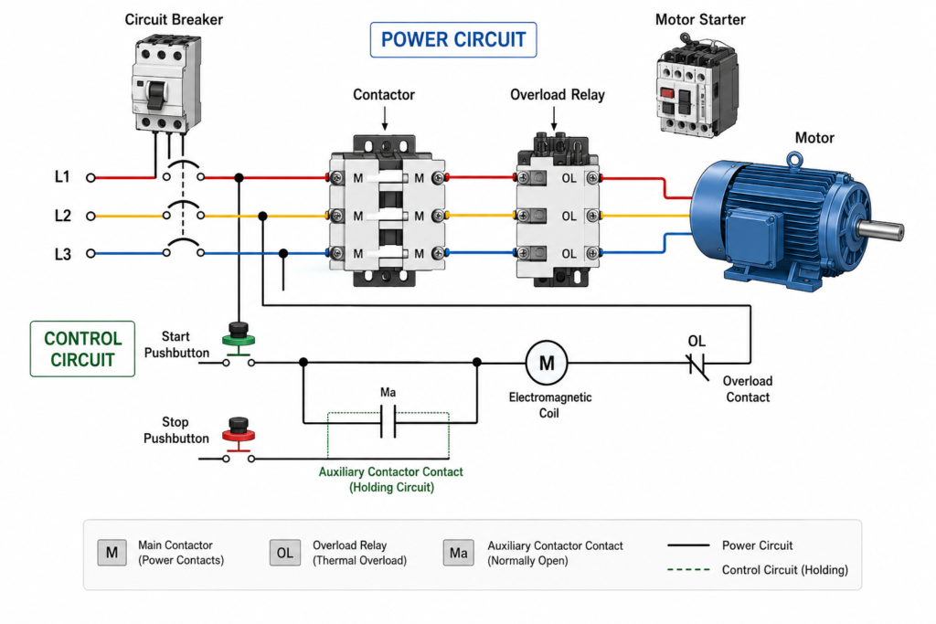
The most basic motor-control system combines switching and protection.
The contactor turns the motor on and off. The overload relay protects it against sustained excessive current. Fuses or a circuit breaker protect the branch circuit against short-circuit current.
For one or two motors, these components may be installed in local panels. In larger facilities, multiple combination starters are grouped inside a motor control center.
The basic structure can be summarized as:
Short-circuit protection
↓
Contactor
↓
Overload relay
↓
Motor
Understanding this arrangement creates the foundation for more advanced systems involving reversing starters, soft starters, VFDs and PLC-controlled MCCs.